EP0582116A1 - Procédé pour déterminer la position des guides d'ondes lumineuses et dispositif pour mettre en oeuvre le procédé - Google Patents
Procédé pour déterminer la position des guides d'ondes lumineuses et dispositif pour mettre en oeuvre le procédé Download PDFInfo
- Publication number
- EP0582116A1 EP0582116A1 EP93111486A EP93111486A EP0582116A1 EP 0582116 A1 EP0582116 A1 EP 0582116A1 EP 93111486 A EP93111486 A EP 93111486A EP 93111486 A EP93111486 A EP 93111486A EP 0582116 A1 EP0582116 A1 EP 0582116A1
- Authority
- EP
- European Patent Office
- Prior art keywords
- group
- optical fibers
- optical
- intensity distribution
- light
- Prior art date
- Legal status (The legal status is an assumption and is not a legal conclusion. Google has not performed a legal analysis and makes no representation as to the accuracy of the status listed.)
- Granted
Links
- 238000000034 method Methods 0.000 title claims description 117
- 239000013307 optical fiber Substances 0.000 claims abstract description 235
- 238000009826 distribution Methods 0.000 claims abstract description 158
- 230000003287 optical effect Effects 0.000 claims description 146
- 230000000875 corresponding effect Effects 0.000 claims description 62
- 230000008569 process Effects 0.000 claims description 57
- 238000003466 welding Methods 0.000 claims description 48
- 238000006073 displacement reaction Methods 0.000 claims description 33
- 238000011156 evaluation Methods 0.000 claims description 22
- 230000008878 coupling Effects 0.000 claims description 18
- 238000010168 coupling process Methods 0.000 claims description 18
- 238000005859 coupling reaction Methods 0.000 claims description 18
- 230000002123 temporal effect Effects 0.000 claims description 17
- 238000005314 correlation function Methods 0.000 claims description 11
- 230000002596 correlated effect Effects 0.000 claims description 2
- 230000000007 visual effect Effects 0.000 claims 1
- 238000005259 measurement Methods 0.000 description 44
- 239000000835 fiber Substances 0.000 description 23
- 230000005855 radiation Effects 0.000 description 20
- 230000005540 biological transmission Effects 0.000 description 18
- 238000013016 damping Methods 0.000 description 13
- 239000003365 glass fiber Substances 0.000 description 10
- 101150052726 DSP2 gene Proteins 0.000 description 8
- 230000004888 barrier function Effects 0.000 description 8
- 238000005452 bending Methods 0.000 description 8
- 230000008901 benefit Effects 0.000 description 7
- 238000011161 development Methods 0.000 description 6
- 230000018109 developmental process Effects 0.000 description 6
- 230000001105 regulatory effect Effects 0.000 description 5
- 239000000654 additive Substances 0.000 description 4
- 230000000996 additive effect Effects 0.000 description 4
- 230000006870 function Effects 0.000 description 4
- 238000012937 correction Methods 0.000 description 3
- 238000005516 engineering process Methods 0.000 description 3
- 239000011521 glass Substances 0.000 description 3
- 239000006060 molten glass Substances 0.000 description 3
- 230000007704 transition Effects 0.000 description 3
- 101001056108 Xenopus laevis Protein max Proteins 0.000 description 2
- 239000003086 colorant Substances 0.000 description 2
- 230000000694 effects Effects 0.000 description 2
- 230000006872 improvement Effects 0.000 description 2
- 239000000463 material Substances 0.000 description 2
- 210000002023 somite Anatomy 0.000 description 2
- 238000012935 Averaging Methods 0.000 description 1
- 101150115013 DSP1 gene Proteins 0.000 description 1
- 241001295925 Gegenes Species 0.000 description 1
- 206010044565 Tremor Diseases 0.000 description 1
- 206010000210 abortion Diseases 0.000 description 1
- 238000013459 approach Methods 0.000 description 1
- 230000006399 behavior Effects 0.000 description 1
- 230000008859 change Effects 0.000 description 1
- 239000011248 coating agent Substances 0.000 description 1
- 238000000576 coating method Methods 0.000 description 1
- 238000004040 coloring Methods 0.000 description 1
- 238000011109 contamination Methods 0.000 description 1
- 230000007423 decrease Effects 0.000 description 1
- 230000006735 deficit Effects 0.000 description 1
- 230000001934 delay Effects 0.000 description 1
- 238000003780 insertion Methods 0.000 description 1
- 230000037431 insertion Effects 0.000 description 1
- 238000004519 manufacturing process Methods 0.000 description 1
- 230000002028 premature Effects 0.000 description 1
- 230000009467 reduction Effects 0.000 description 1
- 230000004044 response Effects 0.000 description 1
- 230000000284 resting effect Effects 0.000 description 1
- 238000005070 sampling Methods 0.000 description 1
- 238000003860 storage Methods 0.000 description 1
Images



Classifications
-
- G—PHYSICS
- G02—OPTICS
- G02B—OPTICAL ELEMENTS, SYSTEMS OR APPARATUS
- G02B6/00—Light guides; Structural details of arrangements comprising light guides and other optical elements, e.g. couplings
- G02B6/24—Coupling light guides
- G02B6/255—Splicing of light guides, e.g. by fusion or bonding
- G02B6/2551—Splicing of light guides, e.g. by fusion or bonding using thermal methods, e.g. fusion welding by arc discharge, laser beam, plasma torch
Definitions
- the invention relates to a method for determining the position of optical fibers in two groups to be aligned with one another, light being coupled into at least one optical fiber of a group.
- a method of this type is known from DE 39 00 406 A1.
- a reflecting mirror is arranged adjacent to the glass fibers of a pair of ribbon cables. Illuminating light is introduced into the glass fibers in a plane that is different from the normal direction of a plane formed by the glass fibers. On the one hand, an image is observed that is created by the illuminating light, which is reflected by the mirror and then guided through the glass fibers. An image is also considered, which is formed by the illuminating light which is guided through the glass fibers and then reflected by the mirror.
- the invention has for its object to show a way how the local intensity distribution and thus the local position of the optical waveguide in two groups to be aligned can be determined more easily and reliably.
- this object is achieved in a method of the type mentioned at the outset in that a first of the two groups is displaced at least once relative to the other second group in at least one plane transverse to the longitudinal axis of the optical waveguides, during the displacement process from at least one optical waveguide in the second group, light is continuously coupled into at least one optical waveguide of the first group, that the temporal course of the intensity distribution of the coupled light in the first group is determined and that the local intensity distribution of the optical waveguides is recorded from the temporal distribution for evaluation purposes.
- the invention is characterized in particular by the fact that a simple relative movement of the two groups of optical fibers relative to one another results in the local intensity distribution of the optical fibers in the two groups can be determined individually, i.e. selectively for each optical fiber, directly. From the group-wise local intensity distributions of the optical waveguides, their actual, local position, ie their position relative to each other, can be individually determined with a high spatial resolution. The simple shifting movement can be carried out with little effort. In addition, in most measuring devices for optical fibers, such as, for example, splicers or loss measurement devices, there are already holding devices or adjusting elements for displacing the optical fibers. An additional, mechanical effort to carry out the method according to the invention is therefore not necessary in this case. At the same time, the simple displacement movement of the two groups relative to one another has the advantage that an image of the relative position of the two groups of optical waveguides relative to one another can be determined relatively quickly.
- the optical waveguides of a group can each be mechanically connected to one another, preferably in an outer jacket of a ribbon cable.
- the relative local distribution or position of the optical fibers in such a mechanically fixed association can be reliably determined without detaching or exposing the optical fibers.
- proportions of the light power carried in each of the optical waveguides can be individually measured directly. It is therefore possible to measure a quantity which is proportional to the light output carried. Knowledge of the actually performed light output (in mW) is not necessary for the measurement and evaluation.
- the local intensity distribution of the optical waveguides in the first group is obtained in a first measuring process and then the local intensity distribution of the optical waveguides in the second group in a second measuring process.
- light from the locally to be measured optical fibers of the first group is first in at least one observation or measurement optical fiber of the second group and then light from at least one optical fiber of the second group in at least one observation or measurement optical fiber of the first Group coupled.
- the observation optical waveguide for the first or second group is expediently moved relative to the optical waveguides to be measured in at least one plane transverse to its longitudinal axis.
- the observation optical waveguide can be, for example, a selected optical waveguide from the opposite group, which has not yet been investigated, or a measuring optical waveguide to be provided specifically.
- the two recorded total intensity distributions of the optical waveguides of the two groups can advantageously be correlated with one another, so that the location of maximum agreement or “relationship” between the two groups can be determined. This place of optimal orientation, i.e. Optimal alignment state, between the two groups can then be approached in particular for welding two ribbon cables, in which it is not possible to individually align corresponding pairs of optical fibers.
- the optical fibers of the first group are displaced relative to one another at least once in at least one plane transverse to the longitudinal axis of the optical fibers of the second group. From the course of time of the Intensity distribution of the coupled light from the optical fibers of the second group to the optical fibers of the first group (or vice versa) can advantageously be obtained directly the relative position of the optical fibers of the first group compared to the optical fibers of the second group.
- the displacement movement of the first group with respect to the second group is expediently started from a position at which a maximum for each individual optical fiber pair for their individual intensity distribution or individual power level or coupling efficiency can still be exceeded. For this, e.g. move the first group towards the second group so far that they no longer face each other. It can also be advantageous to move the first group back and forth only slightly, i.e. to perform a kind of trembling ("jitter" movement).
- the "jitter" movement has the advantage that at relatively high speeds only relatively small displacement movements of the two groups relative to one another are required for taking a measurement. In particular, in the case of the jitter movement, the first group is moved back and forth relative to the second group by approximately the largest remaining offset of the worst-aligned lightwave pair. This procedure enables a very quick and precise determination of the position of the two groups of optical fibers relative to one another in a simple manner.
- the total intensity distribution or total power distribution or total coupling efficiency during the shifting movement or “jitter” movement is advantageously registered for which all corresponding pairs of optical waveguides together have their greatest, simultaneously over the course of the measured total intensity distribution, show individual individual intensity distributions or power levels.
- the associated shift location then expediently determines the optimal alignment state, ie the location of maximum “relationship” between the two groups to be aligned with one another.
- a splice connection can be carried out between the two groups of optical fibers to be connected to one another for the optimal alignment state obtained with the aid of the displacement movement or jitter movement.
- This plays with multi-fiber connections, e.g. in the case of two ribbon cables to be welded to one another, since in the case of two mechanically fixed groups of optical fibers, an individual, aligned, i.e. ideal alignment of the cores of two corresponding optical fibers of the first and second group is not possible.
- the optimal alignment state i.e. at the location of maximum kinship, carry out a splice connection, in particular welding corresponding optical fiber pairs or optical fiber combinations in a multiple splicer. This advantageously enables sufficiently good splice connections between in each case two corresponding optical waveguides of the first and second group with a simultaneous reduction in costs and production time per individual splice connection.
- the invention further relates to a method for splicing a first and a second group (G1 *, G1) of optical fibers, light being coupled into at least one of the optical fibers (for example LW1 to LW4) of a group (for example G1), which is characterized in that the splicing of the optical fibers (LW1 * to LW4 *) of the first group (G1 *) with the optical fibers (LW1 to LW4) of the second group (G1) is controlled by means of the temporal intensity distribution of the light which is transmitted during the Splicing of at least one optical fiber (for example LW2) of the second group into at least one optical fiber (for example LW2 *) of the first group is coupled over.
- a method for splicing a first and a second group (G1 *, G1) of optical fibers, light being coupled into at least one of the optical fibers (for example LW1 to LW4) of a group (for example G1) which is characterized in that the splicing of
- the following can be carried out particularly expediently: from the course of the local overall intensity distribution of the light guided in the observation optical waveguide or in the optical waveguides of the second group, the corresponding pair of optical waveguides is identified in a simple manner has the greatest radial offset in the optimal viewing position.
- the smallest relative power level in the overall intensity distribution or in the overall power level is uniquely assigned to this optical fiber combination.
- the smallest relative power level is the smallest absolute power level in relation to the maximum absolute power measured in the aligned state. It is difficult to measure the smallest power level in absolute terms (and it is not necessary for the evaluation), since the level received depends, among other things, on the coupling and decoupling efficiencies of the transmitter and receiver (e.g.
- Optical fibers For the most accurate determination of optical transmission parameters after connecting the two groups of Optical fibers, in particular the splice attenuation when welding the optical fibers of two ribbon cables, are considered as a total of the following three independent measuring steps:
- a first measurement step the two still unconnected and unaligned groups or ribbon cables are shifted against each other (e.g. by a jitter movement) in such a way that there is an individual, ideal alignment for each corresponding pair of optical fibers (in time or in succession also simultaneously for several or all optical fibers to be aligned.).
- the power level at the ideal location is registered individually for each fiber optic combination.
- the two ribbon cables are moved into an optimal alignment state, which can be determined from the temporal course of the overall intensity distribution during the relative displacement movement or jitter movement of the two groups with respect to one another.
- the optimal alignment state the power levels for the corresponding optical fiber combinations are also recorded selectively.
- the corresponding pairs of optical fibers are finally spliced to one another in the optimum alignment state, in particular welded, and the associated power levels for the optical fiber combinations are also recorded here.
- the actual, individual optical transmission parameters, in particular the splice loss for each optical fiber pair connected to one another can be calculated selectively with high accuracy.
- the implementation of the three measuring steps is not bound to the method according to the invention for determining the position of optical waveguides, but is also advantageously possible in combination with other methods and devices for determining the position of optical fibers (e.g. in video recording methods).
- the invention also relates to a device for carrying out the method, which is characterized in that a first holding device with a first group of optical fibers is arranged so as to be displaceable in at least one plane transverse to the longitudinal axis of the optical fibers relative to a second holding device with a second group, that a receiving device is provided for recording the temporal course of the intensity distribution of the light coupled from at least one optical waveguide of the second group into at least one optical waveguide of the first group, and that a storage device is provided which determines and adjusts the local intensity distribution of the optical waveguides from the temporal intensity distribution Records evaluation purposes.
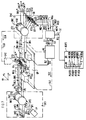
- the right part of FIG. 1 shows a first group G1 * with, for example, four optical fibers LW1 * to LW4 *, and in the left part a second group G1 with, for example, four optical fibers LW1 to LW4.
- These two groups G1 * and G1 are to be aligned with one another or, if appropriate, connected to one another, in particular welded to one another.
- the optical waveguides LW1 * to LW4 * or LW1 to LW4 can, for example, be arranged loosely, in particular unstructured, but can also advantageously be mechanically connected to one another in the form of a ribbon cable by means of a sheath that firmly encloses them.
- the optical waveguides LW1 * to LW4 * are mechanically fixed in parallel in an approximately rectangular ribbon cable BL1 next to one another.
- the optical fibers LW1 * to LW4 * embedded in an outer sheath BH1 are indicated by dash-dotted lines at the ends.
- the optical waveguides LW1 to LW4 of the group G1 are also mechanically fixed in parallel in an approximately rectangular ribbon cable BL2.
- the outer shell BH2 is shown in the left part of Figure 1.
- the strip line BL1 is attached in a holding device HL1, and the strip line BL2 in a holding device HL2.
- the holding devices HL1 and HL2 are arranged on a common base plate GP.
- the two strip lines BL1 and BL2 to be aligned with one another are freed from their outer sheath BH1 or BH2 for a subsequent splicing process (for example welding process) in the region of their opposite ends.
- the detached optical waveguides LW1-LW4 become approximately V-shaped guide grooves N1 to N4, which extend approximately parallel to the longitudinal axis of the optical waveguides, of a guiding means which is also approximately rectangular Plate is formed, introduced.
- the guide grooves N1 * to N4 * or N1 - N4 expediently have a cross-sectional width which corresponds approximately to the width of the optical fibers LW1 * to LW4 * or LW1 - LW4 to be inserted.
- the guide grooves N1 * to N4 * or N1 to N4 of the two guide means expediently have equidistant spacings in order to be able to bring the approximately parallel adjacent optical waveguides LW1 * to LW4 * or LW1 to LW4 into a defined, positionally secure initial state.
- the guide means are advantageously attached to the side of the holding devices HL1 and HL2 on which the two groups G1 * and G1 to be aligned with one another face each other at their alignment point.
- the local intensity distribution of their associated optical fibers LW1 * to LW4 * or LW1 to LW4 within groups G1 * and G1 is determined with the highest possible spatial resolution.
- the position of greatest possible correspondence, that is to say the location of maximum “kinship”, between the two groups G1 * and G1 can be determined from these intensity distributions.
- the respective local position distributions of the optical waveguides within each group are carried out by means of the following two measurement steps to be carried out independently of one another. The order of the two measuring steps is irrelevant.
- the local intensity distribution of the optical fibers LW1 to LW4 in group G1 is determined and examined.
- the procedure is such that a transmitter SE1 to all optical fibers LW1 to LW4 of the ribbon cable BL2 is coupled.
- the transmission device SE1 is shown schematically in the left part of FIG. 1.
- This transmission device SE1 is designed such that optical measurement signals P1 to P4 are coupled into the optical waveguides LW1 to Lw4 in the direction of the alignment point, advantageously by means of a bending coupler as shown on the right-hand side of FIG. 1 and designated BK1.
- the measurement signals P1 to P4 are symbolically indicated by an arrow in FIG. 1.
- the measurement signals P1 to P4 are identical, ie, of the same size.
- the optical measurement signals P1 to P4 run through the four optical fibers LW1 to LW4 to the alignment point. There, the associated radiation fields SF1-SF4 selectively emerge from the open ends of the optical waveguides LW1 to LW4.
- the local overall intensity distributions of the optical fibers LW1-LW4 can now be measured by moving at least one observation optical fiber in at least one plane transverse to the longitudinal axis of the optical fibers LW1 to LW4 relative to them.
- the optical waveguide LW1 * of the ribbon cable BL1 to be spliced with the ribbon cable BL2 is chosen as the observation optical fiber.
- observation optical waveguide LW1 * During the relative movement of the observation optical waveguide LW1 *, the radiation fields SF1 to SF4 are successively coupled into the observation optical waveguide LW1 *, the intensity distributions the optical fiber LW1 to LW4 recorded and made available for evaluation.
- the observation optical waveguide LW1 * thus acts like a recording camera that is moved past the measurement objects to be examined.
- the relative movement of the measuring optical waveguide LW1 * with respect to the optical waveguides LW1 to LW4 of group G1 can take place in several ways.
- the group G1 can be arranged in a fixed manner in the holding device HL2, while the observation optical fiber LW1 * is moved past the group G1 by means of the holding device HL1.
- the observation optical waveguide LW1 * can also be arranged in a fixed manner, while the group G1 with the optical waveguides LW1 to LW4 is displaced in the holding device HL2. It is also possible to shift group G1 by means of the holding device HL2 and at the same time the observation optical fiber LW1 * by means of the holding device HL1.
- the displacement process takes place at a constant relative speed, so that the temporal course of the intensity distribution of the light coupled into the observation optical fiber LW1 * corresponds directly to the local intensity distribution of the optical fibers LW1 to LW4 in group G1.
- the movement of the observation optical waveguide LW1 * is expediently carried out at least once in a first direction x parallel to the plane in which the axes of the optical waveguides LW1 to LW4 lie.
- a second displacement movement in the direction of ⁇ perpendicular to the first viewing plane x can then be carried out at least once.
- the time course of the intensity distribution of the injected light of the radiation fields SF1 to SF4 in the observation optical waveguide LW1 * can be determined with a receiving device EM1 framed by dash-dotted lines. This is shown schematically in the right part of FIG. 1.
- the receiving device EM1 has a bending coupler BK1, the guide groove FN1 of which is advantageously so wide that the ribbon cable BL1 is held securely in the bending coupler BK1 against displacement.
- the time course of the intensity distribution in the measuring optical waveguide LW1 * can, for example, advantageously be measured with the aid of a photodiode PD1.
- the photodiode PD1 is arranged and aligned in the reception area of the bending coupler BK1 in such a way that its reception characteristics, such as the reception radiation field EF1, which emerges along the curvature of the optical waveguide LW1 *, are recorded as completely as possible.
- the photodiode PD1 converts the light energy of the decoupled received radiation field EF1, that is to say the time profile of the intensity distribution carried out in the optical waveguide LW1 * into an electrical measurement signal PM.
- This measurement signal PM is fed to a measurement value memory MEM1 via a line DL1 and is held or stored therein.
- the local intensity distribution of the optical waveguides LW1 * to LW4 * of the group G1 * in the ribbon cable BL1 is obtained analogously to the procedure of the first measuring step.
- the transmitter SE1 is coupled to all the optical fibers LW1 * to LW4 * of the ribbon cable BL1 in the right part of FIG. 1, the preferably identical measurement signals P1 * to P4 * in the direction of the alignment point in the four optical fibers LW1 * to LW4 * to be measured. be fed selectively.
- the receiver EM1 is coupled to the ribbon cable BL2 in the left part of FIG. 1.
- the second measuring method is therefore related to the Transmitting device SE1 and receiving device EM1 are performed in mirror image to the arrangement shown in FIG.
- An optical waveguide from group G1 is used as the observation optical waveguide, for example the optical waveguide LW1.
- a displacement process (scanning) transverse to the longitudinal axis of the ribbon cable BL1, ie in the x direction and / or y direction, is advantageously carried out at least once to record the local intensity distribution of the optical waveguides LW1 * to LW4 *.
- the temporal course of the local intensity distribution of the radiation fields decoupled from the optical waveguides LW1 * to LW4 * in the observation optical waveguide LW1 moving relative to them can then be recorded analogously to the first measuring step with the aid of the photodiode PD1 now coupled to the ribbon cable BL2.
- This is then positioned in the reception area of its bending coupler BK1 in such a way that its reception characteristic is aligned with the reception radiation field of the optical waveguide LW1 and detects it approximately completely.
- the light coupled into the optical waveguide LW1 is converted into an electrical measurement signal PM * in the photodiode PD1 and is likewise stored in the measurement value memory MEM1 via the line DL1.
- the group G1 * can be passed through several times in the x and / or in the y direction relative to the observation optical waveguide LW1, ie a shifting process can also be carried out more than once in the same shifting direction.
- the intensity distributions determined in this way can advantageously be averaged for the purpose of greater measuring accuracy and then can only be used for evaluation purposes.
- the measured value memory MEM1 is expediently designed in such a way that it can record or store a multiplicity of intensity distributions PM or PM * of the groups G1 or G1 *.
- the local overall intensity distributions for the optical waveguides of groups G1 and G1 * are advantageously shown visually for the two measuring steps.
- the local intensity distribution of the optical waveguides LW1 to LW4 of the group G1 from the first measuring step is called up from the measured value memory MEM1 and successively transmitted via line DL3 by means of a signal DS3 to a display device AZ1, which is shown in the right part of FIG.
- the snapshot in the display device AZ1 shows four separate individual intensity distributions or envelopes J1 to J4, which are assigned to the four optical fibers LW1 to LW4.
- Their maxima M1 to M4 each characterize the location of maximum light guidance in the optical fibers LW1 to LW4, that is to say in particular the position of the core of the optical fibers LW1 to LW4.
- These maxima M1 to M4 thus determine the exact position of the cores of the optical fibers LW1 to LW4 within the ribbon cable BL2 and can be read directly.
- the intensity distributions J1 to J4 are much narrower and steeper (order of magnitude 10 ⁇ m). The distance between two individual intensity distributions is approximately 260 ⁇ m. From the display in the display device AZ1 it can be seen that the core of the optical waveguide LW3 in the direction of the optical waveguide LW1 is slightly shifted, ie there is no equidistant core distribution within the ribbon cable BL2.
- the course of the local intensity distribution of the optical waveguides LW1 * to LW4 * within the ribbon cable BL1 from the second measurement step is continuously visualized in a display device AZ2, which is indicated by dash-dotted lines in the left half of FIG. 1.
- the measured data recorded in the measured value memory MEM1 for the local intensity distribution of the optical waveguides LW1 * to LW4 * are retrieved from this measured value memory MEM1 and successively passed on to the display device AZ2 via a line DL4 by means of a signal DS4.
- the snapshot in the display device AZ2 shows four separate intensity distributions or envelopes J1 * to J4 *, each with four maxima M1 * to M4 *, which are assigned to the cores of the four optical fibers LW1 * to LW4 * in group G1 *.
- the maxima M1 * to M4 * identify the locations or positions at which the maximum light energy is guided in the optical fibers LW1 * to LW4 *, i.e. they each represent the position of the light-guiding cores in the ribbon cable BL1.
- a manual actuation device HS1 is provided for the operator, by means of which a control signal SS1 for operating the holding device HL1 can be activated via a control line SL1. It is also possible for the operator to shift the holding device HL2 by means of an actuating device HS2 by means of a control signal SS2 via a control line SL2 shown in broken lines.
- Finding and approaching an optimal alignment state can also advantageously be automated by an evaluation in a computing unit COR.
- the operator can slide the two corresponding measurement recordings for the local intensity distributions PMi and PMi * using a manual control SK with the aid of the computing unit COR for comparison and thus the location of maximum overlap of the individual intensities or envelopes 31 to J4 of group G1 with the individual - Find the intensities or envelopes J1 * to J4 * of group G1 *.
- the operator triggers a control signal SS3 with the manual control SK.
- This instructs the computing unit COR via a control line SL3 to read out two corresponding overall measurement recordings of the local intensity distributions PMi and PMi * with i 1 to 4 by means of a signal DS5 via a line DL5 from the measured value memory MEM1 and to shift them overlapping.
- the computing unit COR sends the measurement recordings PMi and PMi * by means of a signal DS8 via a line DL8 to a common display device SAZ. This represents the local intensity distributions PMi and PMi * are shown separately, for example with different gray values or different colors.
- the two corresponding intensity distributions or envelopes from the display devices AZ1 and AZ2, which are shifted by ⁇ x relative to one another, are recorded simultaneously in the display device SAZ, for example.
- the intensity distribution PMi (x) for group G1 is dash-dotted, the intensity distribution PMi * (x) for group G1 *, on the other hand, is shown with solid lines.
- the common overlap area is hatched.
- the joint display of the two intensity distributions or envelopes that are to be optimally covered, ie the overlap area, is expediently carried out in real time in the display device SAZ for manipulation of the shift on the control button SK by the operator.
- the computing unit COR continuously calculates the corresponding shift coordinates, for example the shift coordinate ⁇ x of the groups G1 and G1 * against one another, and transmits them to a display DP which continuously shows the shift coordinate ⁇ x (and in a second shift direction in the upper right corner of the display device SAZ) eg ⁇ y) indicates.
- the computing unit COR now registers the location with maximum total overlap area between the two local intensity distributions PMi (x) and PMi * (x) during the shifting process, records this location of maximum relationship and shows the associated shift coordinates, for example ⁇ xMAX, ⁇ yMAX, in the display device SAZ on the display DP.
- the location of maximum kinship can then be reached manually by the operator, for example, using the actuation device HS1 or HS2.
- Automatic alignment of the band lines BL1 and BL2 to one another is advantageously possible by forwarding the location coordinates ⁇ xMAX and / or ⁇ yMAX for the location of maximum “relationship” from the computing unit COR via a line DL6 to a control and regulating device CTU by means of a signal DS6 will.
- This actuates at least one of the holding devices HL1 or HL2 via assigned control lines SL1 or SL2.
- the control and regulating device CTU can, for example, activate the holding device HL1 via the control signal SS1.
- the holding device HL2 can be operated via the control signal SS2, which is sent to the holding device HL2 via a control line SL2.
- a completely automatic determination of the location of maximum kinship can be carried out in the computing unit COR by calculating the respective overall correlation function, e.g. COR ( ⁇ x), for each direction of displacement, e.g. x-direction between the total intensity distribution PMi of group G1 and the total intensity distribution PMi * of group G1 * can be determined.
- This correlation function, e.g. COR ( ⁇ x) is transmitted via a line DL7 by means of signal DS7 to a display device DSP1 and displayed there over the respective displacement path (e.g. ⁇ x, ⁇ y). Further individual units for this are explained with the aid of FIGS. 3 to 6.
- FIG. 1 can expediently be combined to form a measuring device, for example in the form of a measuring case, or, for example, also be part of an optical fiber splicer or an attenuation measuring device.
- a measuring device for example in the form of a measuring case, or, for example, also be part of an optical fiber splicer or an attenuation measuring device.
- further optical transmission parameters to measure two opposing groups of optical fibers.
- the optical fibers LW1 * to LW4 * of group G1 * can be connected to their corresponding optical fibers LW1 to LW4 of group G1 (e.g. using a welding device SV) or be coupled.
- the two guide means are brought closer to one another with the aid of the holding device HL2 or HL1, so that their axial offset in the z direction disappears and the end faces of the optical fibers abut one another.
- the fiber optic ends protrude a few mm beyond the guide means to ensure even heat distribution during welding.
- the welding device SV can be operated manually and automatically using the control and regulating unit CTU. In FIG. 1, the control and regulating unit CTU activates the welding device SV by means of a signal SS5 via a control line SL5 indicated by dash-dotted lines.
- Suitable specific control criteria for setting the welding time t in the computing unit COR can be derived from the two previously determined intensity distributions PMi * and PMi for the groups G1 * and G1 and transmitted to the control and regulating device CTU with the aid of a signal SS7 via the line SL7 will.
- the overcoupled light output can advantageously be used for the corresponding pair of optical fibers that has the greatest remaining radial offset in the optimal alignment state, since individual alignment is usually not possible in multi-fiber connection technology.
- This worst-aligned pair of optical fibers can be found, for example are that the computing unit COR identifies those two corresponding individual intensity distributions that have a minimal, individual overlap area in the optimal alignment state from the shifted overall intensity distributions PMi and PMi *.
- the computing unit COR identifies those two corresponding individual intensity distributions that have a minimal, individual overlap area in the optimal alignment state from the shifted overall intensity distributions PMi and PMi *.
- the computing unit COR identifies those two corresponding individual intensity distributions that have a minimal, individual overlap area in the optimal alignment state from the shifted overall intensity distributions PMi and PMi *.
- the two corresponding individual intensity distributions J3 and J3 * show the smallest overlap area among the two mutually displaced individual intensity distributions J1 - J4 of group G1 and J1 * - J4 * of group G1 *.
- the cores of the optical fiber pair LW3 / LW3 * are poorly aligned.
- the photodiode PD1 of the receiver EM1 is aligned on the receiving side of the receiving field of the optical fiber LW3 *.
- This can expediently be carried out automatically with the aid of the computing unit COR, which transmits a control signal SS6 via a dash-dotted control line SL6 to an actuator BPD for the photodiode PD1.
- the light coupled from the optical waveguide LW3 of group G1 into the optical waveguide LW3 * of group G1 * is then continuously measured with the aid of photodiode PD1, converted into electrical measurement signal PM and transmitted to measured value memory MEM1 via line DL1.
- the measurement signal PM is finally transmitted to the computing unit COR by means of the signal DS5 via the line DL5.
- This received signal can advantageously be used as a specific control criterion for the welding time t during the welding of the two groups G1 and G1 *. The reason for this is that with the help of this measure an optimal splicing result for the poorly aligned and therefore most critical optical fiber pair with regard to the splicing process can be ensured.
- FIG. 2 shows two reception levels of the light PS (t) coupled in at the alignment point as a function of the welding time t for the corresponding pair of optical fibers LW3 / LW3 * and LW4 / LW4 *.
- the measurement curve YES results for an almost ideally aligned optical fiber pair such as LW4 / LW4 *, and the measurement curve SA for a relatively poorly aligned optical fiber pair such as LW3 / LW3 *.
- the almost perfectly aligned LW4 / LW4 * pair of optical fibers results in a relatively flat curve from the start of the welding process at time tO over a relatively long welding time.
- the measurement curve SA has an increase in the measurement level PS (t) up to a time ts from the welding instant tO. After this point in time ts, on the other hand, the reception level PS (t) decreases again, that is to say the attenuation at the alignment point or weld point increases again.
- the poorly aligned optical fiber pair LW3 / LW3 * there is therefore an optimal time ts or time range after starting the welding process at time tO, at which the welding process should be stopped as possible, since there a maximum MP for the reception level PS (t) , ie there is minimal damping.
- the welding process is terminated approximately at time ts, it can advantageously be achieved that the remaining radial offset disappears in the optimal alignment state of groups G1 and G1 * for the poorly aligned fiber optic pair LW3 / LW3 * due to the surface tension of the molten glass.
- the damping remains largely minimal after the welding process has ended. In this way, it is advantageously ensured that the LW3 / LW3 * optical fiber pair, which is poorly aligned, is in the optimal alignment state of the two groups G1 and G1 * the best possible welding result is obtained.
- This method therefore aborts the welding process at the time ts at which the misalignment of the poorly aligned optical waveguide pair LW3 / LW3 * is zero due to the surface tension of the glass.
- This also guarantees good splice results for all other fiber optic pairs in groups G1 and G1 *. Inadmissibly high core bends due to the surface tension of the molten glass or other profile damage are largely avoided by the premature termination of the welding process at the maximum reception level for the poorly aligned pairs of optical fibers.
- FIG. 3 shows an example of a total intensity distribution or total envelope PMi (x) obtained from the method according to the invention according to FIG. 1 for the optical waveguides LW1 to LW4 of the ribbon cable BL2 for a displacement movement shown in the x direction.
- the total intensity distribution PMi (x) has four associated individual intensity distributions or envelopes E1 to E4 for the four optical waveguides LW1 to LW4.
- Each of these four envelopes E1 to E4 envelops three discrete measurement values, as can be obtained, for example, with the aid of an analog / digital converter from the measurement signals PM continuously recorded by the photodiode PD1 in FIG.
- TA (TA scanning distance) assigned.
- the envelope E1 thus has, for example, the three quantized intensity measured values DJ1, DJ2 and DJ3 at a distance TA.
- the four envelopes E1 to E4 each show four maxima DM1 to DM4, each of which characterize the location of maximum light output in the optical waveguides LW1 to LW4 and thus in each case the center of the optical waveguide core.
- a continuous total intensity distribution or total envelope PMi * (x) over the continuous location coordinates x is recorded for the optical waveguides LW1 * to LW4 * of the ribbon cable BL1.
- the intensity distribution PMi * (x) also has four associated envelopes E1 * to E4 * for the four optical fibers LW1 * to LW4 *, each of which surrounds three discrete measured values at the scanning distance T.
- the envelope E1 * envelops the quantized measured values DJ1 *, DJ2 * and DJ3 *.
- the envelopes E1 * to E4 * identify the centers of the cores of the optical fibers LW1 * to LW4 * by maxima DM1 * to DM4 *.
- the envelope E1 * extends over the same x-coordinate section as the envelope E1, that is to say the cores of the optical waveguides LW1 * and LW1 are ideally aligned with one another there.
- the envelope E2 * has been shifted somewhat to the left relative to the envelope E2 *, that is to say the core of the optical waveguide LW2 * has shifted somewhat to the left compared to the core of the optical waveguide LW2.
- the envelopes E3 * and E4 * are shifted slightly to the right compared to the envelopes E3 and E4, i.e. the optical fibers LW3 * and LW4 * are also not aligned with the optical fibers LW3 and LW4.
- FIG. 5 there is a cross-correlation function plotted against the relative discrete displacement n that is obtained when the total discrete intensity distribution of Figure 3 with the discrete total intensity distribution of Figure 4 is cross-correlated.
- the cross correlation function the discrete total intensity distributions and is defined by The discrete cross correlation function has seven maxima KM1 to KM7.
- the mean maximum KM4 is within the discrete distribution of the absolute maximum MAX
- the maximum of these discrete cross-correlated identifies the discrete displacement path or location at which all four discrete individual distributions, that is to say the three samples in each case in the envelopes E1 to E4, of with the four associated, discrete individual distributions, that is, each with the three samples in the envelopes E1 * to E4 *, from overlap as much as possible.
- the discrete cross-correlation function is of practical interest by a functional dependency (such as, for example, using polynomial interpolation or using Shannon's sampling theorem), since the resolution of the x-coordinates is limited by the distance TA between two intensity values.
- FIG. 7 the elements adopted unchanged from FIG. 1 are provided with the same reference numerals as in FIG. 1.
- the group G1 with the optical fibers LW1 to LW4 in the holding device HL2 is different 1 also embedded in the area of the alignment point, which is designated AS here, by the outer, approximately rectangular, flat sheath BH2 of the ribbon cable BL2.
- the holding device HL2 can optionally be displaced in three different spatial directions x, y and z.
- the group G1 * with the optical waveguides LW1 * to LW4 * in the holding device HL1 in the area of the alignment point is still surrounded by the outer, approximately rectangular envelope BH1 of the ribbon cable BL1 and, if necessary, movable in the x, y and z direction.
- the longitudinal axes of the optical waveguides LW1 - LW4 and LW1 * - LW4 * are indicated by dash-dotted lines in the ribbon cables BL2 and BL1.
- the two holding devices HL1 and HL2 are mounted on a common, fixed base plate GP for better handling.
- the two ribbon lines BL1 and BL2 are intended with respect to the two groups G1 * and G1 of optical fibers, i.e. in groups, optimally aligned with each other in order to then be able to reliably perform, for example, an attenuation measurement or a splicing process for each optical fiber combination of the two groups in this optimal alignment state.
- each transmission signal SP1 to SP4 are coupled into the optical waveguides LW1 to LW4 of the ribbon cable BL2 with the aid of a transmission device SE3 for optimum position determination.
- the optical fibers LW1 - LW4 of the ribbon cable BL2 are placed around a cylinder ZT3 of the bending coupler BK3 and are guided in the guide groove FN3 so that the transmission signals SP1 to SP4 can enter the optical waveguides LW1 to LW4 almost tangentially.
- the transmit signals SP1 to SP4 are symbolically indicated by an arrow. As shown in FIG.
- the transmitting device SE3 either has only a single light source LA, such as a laser diode, to which all the optical fibers LW1 to LW4 to be measured are coupled, or has a separate light source for each optical fiber LW1 to LW4 to be coupled.
- the transmission signals SP1 to SP4 can also be fed in directly via the open end faces of the optical fibers LW1 to LW4. As in FIG. 7, they can advantageously come from a specially provided measuring transmitter, such as the light source LA, but can also be message signals in the optical fibers LW1 to LW4.
- the transmission signals SP1-SP4 coupled into the optical waveguides LW1-LW4 are identical, i.e. are the same size. Furthermore, the same coupling factors apply to all four fiber-optic cable combinations LW1 / LW1 * to LW4 / LW4 * in the transmission-side coupling and in the receiving-side coupling.
- the four measurement signals P1 to P4 are carried in the optical fibers LW1 to LW4 up to the alignment point AS, which is indicated by dash-dotted lines in FIG. There the associated four radiation fields SF1 to SF4 then selectively emerge from one another.
- the ribbon cable BL2 with the optical fibers LW1 to LW4 is initially opposed to the ribbon cable BL1 with the optical fibers LW1 * to LW4 * in any unaligned position.
- the two ribbon lines BL1 and BL2 are now moved relative to one another in such a way that the radiation fields SF1 to SF4 coupled out of the optical fibers LW1 to LW4 are coupled to one another in the optical fibers LW1 * to LW4 * in different positions or positions of the two ribbon lines BL1 and BL2.
- the ribbon cable BL1 in the holding device HL1 is compared to the fixed ribbon cable BL2 in the holding device HL2 in at least one direction parallel to that plane in which the longitudinal axes of the optical fibers LW1-LW4 lie, preferably in x- and / or y- Shifted direction at least once.
- This displacement movement detects the radiation fields SF1-SF4 coupled out of the optical waveguides LW1 to LW4 in each case by the assigned, corresponding optical waveguides LW1 * to LW4 * in different spatial positions.
- the optical waveguide LW1 * takes up the radiation field SF1 of the measurement signal P1 decoupled from the optical waveguide LW1 successively, ie continuously, at different x positions during a displacement process in the x direction.
- a shift in the y direction or a shift in another spatial direction is carried out transversely, ie orthogonally, to the longitudinal axis of the ribbon cable BL2.
- the shifting process of the ribbon cable BL1 is expediently started from a position in which for each pair of optical fibers, e.g. LW1 / LW1 *, in each case a maximum for their individual intensity distribution can be exceeded.
- This can be achieved in a simple manner, for example, by completely pulling the ribbon cable BL1 out of the alignment point AS and starting the displacement process from there.
- the simple relative movement of the two groups G1 and G1 * of optical waveguides against one another is expediently carried out by at least the maximum displacement of two corresponding optical waveguides in groups G1 and G1 * in the respective displacement direction.
- jitter a type of jitter
- the "jitter" movement for the strip line BL1 takes place, for example, in the x direction in such a way that it is first moved by a small amount ⁇ x in the positive x direction and then one Direction reversal by ⁇ x in the negative x direction.
- This back and forth movement can advantageously be carried out several times.
- disturbance variables such as mechanical play of the holding devices, hysteresis and creeping, their piezo elements can be largely eliminated.
- the "jitter" movement has the advantage that only relatively small displacement movements of the ribbon cables BL1 and BL2 relative to one another are required in order to be able to draw conclusions and conclusions about their optimal alignment state relative to one another.
- a shift by at least the respective radiation field width of two corresponding optical waveguides out of their respectively perfectly aligned alignment state is required (approximately 10 ⁇ m).
- the "jitter" method thus ensures in a simple manner that the transmission maximum of two corresponding optical fibers, such as for LW1 / LW1 *, can be detected in any case.
- the time course of the intensity distribution of the optical fibers LW1 * to LW4 * is recorded continuously, ie continuously, with the aid of a receiving device EM2.
- This receiving device EM2 advantageously has a bending coupler BK2 with a cylinder ZT2, in whose guide groove FN2 the ribbon cable BL1 is inserted.
- the aid of at least four light-sensitive elements LE1 to LE4 which are arranged on a common base plate GU, which is only shown in broken lines, four receiving radiation fields ES1 to ES4, which are coupled out along the curvature of the optical waveguides LW1 * to LW4 *.
- the light-sensitive elements can preferably be combined in the form of a multi-quadrant diode of a multi-quadrant array or CCD array, which usually has well over 100 light-sensitive elements (eg 1024 x 1024 elements for video standard).
- the light-sensitive elements LE1 to LE4 generate electrical measuring signals MS1 to MS4 from the radiation fields ES1 to ES4 and feed them to a measured value memory MEM2 via separate measuring lines ML1 to ML4. This selectively records the time course of the light coupled out of the optical fibers LW1 * to LW4 *.
- An evaluation device AE now searches the signals S1 (measuring sequences) arriving continuously from the measured value memory MEM2 via the line B1 for a shifting process for that total or group intensity distribution or that total reception level which is required for all four optical fiber combinations LW1 / LW1 * to LW4 / LW4 * has the largest single intensity maximum (or the largest reception level) at the same time.
- the strip line BL1 is moved in the x direction by means of the holding device HL1 with respect to the resting strip line BL2.
- the evaluation device AE controls the holding device HL1 via the control line SL1 with the aid of the control signal SS1. (corresponding to the control lines for Figure 1).
- the holding device HL2 can be actuated via the control line SL2 shown in broken lines with the aid of the control signal SS2.
- the four pairs of optical fibers LW1 / LW1 * to LW4 / LW4 * are assigned four envelopes P1VER to P4VER as individual intensity distributions. These envelopes P1VER to P4VER show four maxima M1VER to M4VER, all within a tolerance range T. lie between an upper barrier OS and a lower barrier US.
- the maxima M1VER to M4VER each represent the location of maximum light guidance, ie the centers of the aligned cores of the pairs of optical fibers to be measured.
- the lower barrier US marks that intensity value that is required in each case at least for an alignment position of one of the optical waveguide pairs that is still permissible.
- the upper bound OS characterizes that intensity value that can be attained as far as possible for an ideally aligned pair of optical fibers.
- the fiber-optic cable combination LW2 / LW2 * represents the worst-aligned pair of optical fibers, since its associated envelope P2VER with its maximum value M2VER is only just above the lower, permissible limit US. Further details on the evaluation of the overall intensity distribution are described in FIGS. 8 and 10.
- the optical fibers LW1-LW4 are connected in pairs with the optical fibers LW1 * - LW4 * with the help of a dash-dotted welding device SV2.
- the fiber optic cable combinations LW1 / LW1 * -LW4 / LW4 * are expediently (according to FIG. 1) freed from their outer sheathings BH2 * to BH1 beforehand, ie before the alignment and welding process.
- the welding device SV2 is operated by the evaluation device AE via a line SL8 shown in broken lines by means of a control signal SS8.
- the welding process can advantageously be controlled in the manner already described in FIGS. 1 and 2.
- the optimal alignment state can be determined directly with the method according to FIG. 7 according to the invention.
- the simple relative movement or "jitter" movement of the two ribbon cables against one another further simplifies the measuring process and increases the working speed.
- the measuring devices according to the invention according to FIGS. 1 and 7 can advantageously be part of a damping measuring device or a splicer for multi-fiber technology.
- their respective components can each be combined to form a measuring case.
- FIGS. 8 to 10 optical transmission parameters such as e.g. the splice attenuation when connecting two groups of optical fibers, in particular when welding two ribbon cables, the method according to the invention according to FIG. 7 is carried out by way of example. Elements adopted unchanged from FIG. 7 are given the same reference numerals in FIGS. 8 and 10.
- FIGS. 8 and 10 show the two ribbon lines BL1 and BL2 from FIG. 7 in an enlarged plan view.
- they are first optimally aligned with one another with the aid of the method according to the invention according to FIG. 7 and the measuring device shown there.
- the optical fibers LW1 to LW4 permanently embedded in the outer sheath BH2 of the ribbon cable BL2 are therefore optimal in the range as a group G1 of group G1 * with the optical fibers LW1 * to LW4 *, which are permanently embedded in the outer jacket BH1 of the ribbon cable BL1 assigned to the alignment point AS.
- the optical fibers LW1 to LW4 of the ribbon cable BL2 are expediently at a distance LS1 to LS4 from the optical fibers LW1 * to LW4 * of the ribbon cable BL1 in the region of the alignment point AS between 0 mm and 1 mm with respect to their fiber optic ends.
- the optical fibers LW1 to LW4 or LW1 * to LW4 * are each detached from their outer sheaths BH2 or BH1 and, if necessary, freed of their coating in order to prevent contamination from their sheathing material at the splice point during the welding process and thus impairments to prevent the connection quality as far as possible.
- optical fibers LW1 to LW4 or LW1 * to LW4 * are expediently exposed over a relatively short length, in particular between 3 mm and 10 mm, in the region of the alignment point AS.
- the optical waveguides LW1 to LW4 or LW1 * to LW4 * can advantageously be inserted into guide means for securing the position, as shown by way of example in FIG. 1.
- the position of the optical waveguide cores, that is to say the location of maximum light guidance, of the optical waveguides LW1 to LW4 or LW1 * to LW4 * is indicated by dash-dotted lines in FIGS.
- 10 measuring signals P1 to P4 in accordance with FIG. 7 are fed into the optical waveguides LW1 to LW4 in FIGS.
- the associated radiation fields emerge at the open ends of the optical waveguides LW1 to LW4 in the region of the alignment point AS and are at least partially coupled into the open ends of the optical waveguides LW1 * to LW4 * of the group G1 *.
- the time course of the coupled light into the optical waveguides LW1 * to LW4 * is recorded in accordance with FIG. 7 via measurement signals MS1 to MS4 and continuously displayed in the display device DSP2 in accordance with FIG. In FIGS.
- the intensity distributions required for determining the splice loss are each schematically recorded in the display device DSP2.
- the intensity distribution gives in each case the distribution of the coupled power again, which in turn represents the coupling efficiencies in the transmission coupling and in the receiving coupling of light.
- the splice loss in the x direction the following independent measurement steps are carried out as an example; (the splice loss in the y direction can be determined in an analogous manner). In the following, however, for simplification, it is assumed that all corresponding fiber pairs are already optimally aligned in the y direction, so that, for example, only alignment with respect to the x direction is carried out and discussed.
- the strip line BL1 is moved back and forth in the x direction (corresponding to the coordinate system of FIG. 7) at least once relative to the strip line BL2.
- this back and forth movement (“jitter”) is indicated by a double arrow VR, which points in the positive and negative x-direction.
- the displacement path is made up of the largest misalignment of the worst aligned fiber optic cores, such as in Figure 8 LW2 / LW2 *, as well as the respective radiation field width (approx.
- optical fiber combinations LW1 / LW1 * to LW4 / LW4 * are assigned the individual intensity distributions or individual power distributions E1ID to E4ID as envelopes. Their associated, best possible coupling efficiencies or intensity distributions P1ID to P4ID that occur over time characterize with their maxima M1ID to M4ID the location of aligned, individual alignment of two mutually assigned optical waveguides.
- optical fiber pairs LW2 / LW2 *, LW3 / LW3 * and LW4 / LW4 * are misaligned in the x-direction in the snapshot of FIG. 8.
- E2ID ⁇ P2ID, E3ID ⁇ P3ID, E4ID ⁇ P4ID The pair LW3 / LW3 * is aligned approximately the same as the pair LW1 / LW1 *, so that their maxima are therefore exceeded at about the same time during the displacement movement in the x direction.
- All individual intensity distributions PiVER with i 1 ... 4 lie within a tolerance range T between a lower barrier US and an upper barrier OS.
- the upper barrier OS indicates the maximum achievable power level that can be achieved for an individual alignment of corresponding pairs of optical fibers without an offset in the x direction.
- the lower barrier US indicates that power level that is just tolerable or acceptable for a splice connection with offset.
- the standardization offers the advantage that the evaluation is particularly independent of the alignment state in the y direction and independent of external influencing factors, such as, for example, the different coupling efficiencies in the transmission side coupling and in the receiving side coupling Decoupling of light, as can be caused, for example, by different color applications (different colors, different layer thicknesses, etc. ...) on the optical fibers in the ribbon cables.
- differences in coupling efficiency of up to 30 dB can already occur for the individual optical fibers, which would make an objective evaluation very uncertain. Because of the standardization, it no longer matters whether the individual optical waveguides have transmit or measurement signals and / or receive signals of the same size or different sizes.
- the optical fiber pair LW1 / LW1 * for example in the x direction, is almost without offset, ie ideal aligned, aligned.
- the fiber optic pairs LW2 / LW2 * to LW4 / LW4 * have a remaining but still tolerable offset, whereby the fiber optic combination LW2 / LW2 * has the lowest reception level P2VER and thus the largest remaining offset.
- the two ribbon cables BL1 and BL2 are moved towards one another in this alignment state and the welding process is carried out in accordance with the statements relating to FIGS. 1 and 7, respectively.
- the welding process can advantageously be controlled by the maximum remaining offset of the worst aligned fiber optic pair. In Figure 9 this is the offset of the pair of optical fibers LW2 / LW2 *, which has the greatest attenuation, ie the lowest individual intensity distribution P2VER, in the display device DSP2. If the power falls below the lower barrier US, the welding process is stopped and a new alignment process is started.
- an overall intensity distribution PiS is recorded as an example in the display device DSP2 after the welding process has been carried out.
- the remaining offsets of the two groups of optical fibers disappear due to the surface tension of the molten glass.
- Even for poorly aligned pairs of optical fibers such as an improvement can be achieved here for LW2 / LW2 *. (cf. the explanations in Figure 2), i.e. the damping can be advantageously reduced.
- FIGS. 8 to 10 only the case is dealt with in which the ribbon lines BL1 and BL2 are aligned in the x direction.
- a corresponding alignment of the strip lines BL1 and BL2 to one another can of course also be carried out in any direction transverse to the longitudinal axis of the two strip lines BL1 and BL2 before the welding process.
- the individual, selective attenuation ⁇ avi (x) can expediently be determined by an offset in the x direction and ⁇ avi (y) by a remaining offset in the y direction for two corresponding pairs of optical waveguides to be welded to one another .
Landscapes
- Physics & Mathematics (AREA)
- Engineering & Computer Science (AREA)
- Plasma & Fusion (AREA)
- General Physics & Mathematics (AREA)
- Optics & Photonics (AREA)
- Mechanical Coupling Of Light Guides (AREA)
- Optical Couplings Of Light Guides (AREA)
- Length Measuring Devices By Optical Means (AREA)
- Manufacture, Treatment Of Glass Fibers (AREA)
Applications Claiming Priority (2)
| Application Number | Priority Date | Filing Date | Title |
|---|---|---|---|
| DE4226201 | 1992-08-07 | ||
| DE4226201 | 1992-08-07 |
Publications (2)
| Publication Number | Publication Date |
|---|---|
| EP0582116A1 true EP0582116A1 (fr) | 1994-02-09 |
| EP0582116B1 EP0582116B1 (fr) | 1999-01-27 |
Family
ID=6465099
Family Applications (1)
| Application Number | Title | Priority Date | Filing Date |
|---|---|---|---|
| EP93111486A Expired - Lifetime EP0582116B1 (fr) | 1992-08-07 | 1993-07-16 | Procédé pour déterminer la position des guides d'ondes lumineuses et dispositif pour mettre en oeuvre le procédé |
Country Status (5)
| Country | Link |
|---|---|
| US (1) | US5384870A (fr) |
| EP (1) | EP0582116B1 (fr) |
| JP (1) | JPH06213621A (fr) |
| AT (1) | ATE176334T1 (fr) |
| DE (1) | DE59309338D1 (fr) |
Cited By (1)
| Publication number | Priority date | Publication date | Assignee | Title |
|---|---|---|---|---|
| EP0716323A1 (fr) * | 1994-12-08 | 1996-06-12 | International Business Machines Corporation | Appareil et procédé pour alignement des fibres optiques utilisant une boucle de rétroaction adaptative |
Families Citing this family (9)
| Publication number | Priority date | Publication date | Assignee | Title |
|---|---|---|---|---|
| FR2716981B1 (fr) * | 1994-03-03 | 1996-05-24 | Daniel Boscher | Procédé de connexion optique multivoies pour fibres optiques. |
| FR2736441B1 (fr) * | 1995-07-04 | 1997-09-26 | Noane Georges Le | Dispositif et procede de reperage et de raccordement de fibres multicoeurs |
| JP3500850B2 (ja) * | 1996-04-23 | 2004-02-23 | 住友電気工業株式会社 | リボン型光ファイバの突き合せ部を観察する方法及び観察装置 |
| EP1130429A1 (fr) * | 2000-03-02 | 2001-09-05 | Corning Incorporated | Méthode et dispositif d'alignement et de soudure de fibres optiques |
| JP3756940B2 (ja) * | 2001-07-02 | 2006-03-22 | 古河電気工業株式会社 | 異種光ファイバの接続方法および異種光ファイバの接続部分の加熱処理装置 |
| US7236680B1 (en) * | 2004-08-16 | 2007-06-26 | Pi (Physik Instrumente) L.P. | Aligning apparatus and method using on-the-fly determination of throughput-profile gradient for current positioning of radiated influence supplier and/or receiver |
| US7212723B2 (en) * | 2005-02-19 | 2007-05-01 | The Regents Of The University Of Colorado | Monolithic waveguide arrays |
| DE102006047425A1 (de) * | 2006-10-06 | 2008-04-10 | CCS Technology, Inc., Wilmington | Gerät und Verfahren zum thermischen Verbinden von Lichtleitfasern |
| DE202007010785U1 (de) * | 2007-08-03 | 2007-09-27 | CCS Technology, Inc., Wilmington | Vorrichtung zum Verspleißen von Lichtwellenleitern |
Citations (3)
| Publication number | Priority date | Publication date | Assignee | Title |
|---|---|---|---|---|
| DE2411814B2 (de) * | 1974-03-12 | 1976-02-19 | Siemens AG, 1000 Berlin und 8000 München | Verfahren zum verbinden von in einem strang zusammengefasster lichtleitfasern mit einem anderen, gleichartigen strang |
| EP0303990A2 (fr) * | 1987-08-14 | 1989-02-22 | Fujikura Ltd. | Procédé d'examen de l'état d'alignement de fibres de verre d'une paire de cables-ruban |
| EP0423543A2 (fr) * | 1989-10-20 | 1991-04-24 | Dornier Gmbh | Dispositif pour positionner des fibres optiques |
Family Cites Families (5)
| Publication number | Priority date | Publication date | Assignee | Title |
|---|---|---|---|---|
| CA1245431A (fr) * | 1986-02-13 | 1988-11-29 | Helmut H. Lukas | Dispositif de fusion pour joindre deux fibres optiques monomode bout-a-bout |
| JPH0675023B2 (ja) * | 1988-01-30 | 1994-09-21 | 株式会社フジクラ | 光ファイバの接続損失推定法 |
| US5170456A (en) * | 1988-09-07 | 1992-12-08 | Fujikura Ltd. | Apparatus for aligning a plurality of single-fiber cables |
| EP0400408B1 (fr) * | 1989-06-02 | 1996-11-27 | Siemens Aktiengesellschaft | Procédé pour aligner deux extrémités de fibres optiques et dispositif pour sa mise en oeuvre |
| DE4243388A1 (de) * | 1992-02-05 | 1994-06-23 | Siemens Ag | Meßeinrichtung für Lichtwellenleiter und Verfahren zur Durchführung der Messung |
-
1993
- 1993-07-16 AT AT93111486T patent/ATE176334T1/de not_active IP Right Cessation
- 1993-07-16 DE DE59309338T patent/DE59309338D1/de not_active Expired - Fee Related
- 1993-07-16 EP EP93111486A patent/EP0582116B1/fr not_active Expired - Lifetime
- 1993-08-02 US US08/100,244 patent/US5384870A/en not_active Expired - Fee Related
- 1993-08-09 JP JP5197219A patent/JPH06213621A/ja not_active Withdrawn
Patent Citations (3)
| Publication number | Priority date | Publication date | Assignee | Title |
|---|---|---|---|---|
| DE2411814B2 (de) * | 1974-03-12 | 1976-02-19 | Siemens AG, 1000 Berlin und 8000 München | Verfahren zum verbinden von in einem strang zusammengefasster lichtleitfasern mit einem anderen, gleichartigen strang |
| EP0303990A2 (fr) * | 1987-08-14 | 1989-02-22 | Fujikura Ltd. | Procédé d'examen de l'état d'alignement de fibres de verre d'une paire de cables-ruban |
| EP0423543A2 (fr) * | 1989-10-20 | 1991-04-24 | Dornier Gmbh | Dispositif pour positionner des fibres optiques |
Non-Patent Citations (2)
| Title |
|---|
| NACHRICHTENTECHNISCHE ZEITSCHRIFT Bd. 41, Nr. 4, 1988, BERLIN Seiten 230 - 233 TH.EDER ET AL. 'Einmodenspleisse automatisch messen und herstellen' * |
| ZWF ZEITSCHRIFT FÜR WIRTSCHAFTLICHE FERTIGUNG UND AUTOMATISIERUNG Bd. 85, Nr. 12, Dezember 1990, MUNCHEN DE Seiten 656 - 660 L.KIESEWETTER ET AL. 'Automatisierbare Fügetechniken für Glasfasern in schaltbaren Koppelelementen' * |
Cited By (1)
| Publication number | Priority date | Publication date | Assignee | Title |
|---|---|---|---|---|
| EP0716323A1 (fr) * | 1994-12-08 | 1996-06-12 | International Business Machines Corporation | Appareil et procédé pour alignement des fibres optiques utilisant une boucle de rétroaction adaptative |
Also Published As
| Publication number | Publication date |
|---|---|
| ATE176334T1 (de) | 1999-02-15 |
| EP0582116B1 (fr) | 1999-01-27 |
| JPH06213621A (ja) | 1994-08-05 |
| DE59309338D1 (de) | 1999-03-11 |
| US5384870A (en) | 1995-01-24 |
Similar Documents
| Publication | Publication Date | Title |
|---|---|---|
| DE68902321T2 (de) | Verfahren zum bestimmen der strahlungsverluste von faserverbindungen. | |
| DE3888306T4 (de) | Verfahren und Vorrichtung zum Schweissen von polarisationshaltenden optischen Fasern. | |
| DE69527888T2 (de) | Spleissen von optischen Fasern | |
| EP0582116B1 (fr) | Procédé pour déterminer la position des guides d'ondes lumineuses et dispositif pour mettre en oeuvre le procédé | |
| DE2752688C3 (de) | Optischer Sender einer Vorrichtung zum Messen der Dämpfung optischer Wellen auf optischen Übertragungsstrecken | |
| DE68929169T2 (de) | Durchbruchsfreier optischer Koppler | |
| EP0625261B1 (fr) | Dispositifs de mesure pour plusieurs guides d'ondes lumineuses et procede d'execution de la mesure | |
| EP0899539B1 (fr) | Procédé ainsi que dispositif pour obtenir des informations sur au moins une extrémité d' une fibre optique | |
| DE68905764T2 (de) | Verfahren zur Herstellung eines Faserkopplers. | |
| EP0582831A1 (fr) | Procédé et dispositif pour faire des mesures avec des guides d'ondes lumineuses | |
| DE19643661A1 (de) | Verfahren sowie Vorrichtung zur Bestimmung von Spleißparametern | |
| DE3335579A1 (de) | Optische einrichtung zum beobachten des justierens von lichtwellenleitern | |
| DE4139152B4 (de) | Verfahren zum Spleißen von Lichtwellenleitern | |
| EP0594996A2 (fr) | Atténuateur optique, méthode pour sa fabrication et appareil adapté pour l'épissage par fusion | |
| DE2446152C3 (de) | Justierbare Koppelanordnung zur Verbindung und Ausrichtung von mindestens zwei Lichrwellenleitern eines optischen Nachrichtenübertragungssystems auf einer gemeinsamen optischen Achse | |
| EP0593980B1 (fr) | Procédé et dispositif pour exécuter des mesures sur plusieurs fibres optiques | |
| EP0716736B1 (fr) | Procede et dispositif pour le controle des proprietes d'au moins une epissure d'au moins un guide d'ondes lumineuses | |
| DE19746080A1 (de) | Verfahren sowie Vorrichtung zur Einstellung von Schweißparametern | |
| EP0853246A2 (fr) | Procédé et dispositif pour souder thermiquement au moins deux bouts de fibres optiques | |
| EP1192491B1 (fr) | Determination de l'amortissement d'epissure apres mesure de la geometrie | |
| WO1991012546A1 (fr) | Procede et appareil d'epissure | |
| DE4201068C1 (fr) | ||
| DE4208403C2 (de) | Lichtwellenleiter-Verzweiger in Planartechnik | |
| DE3101577A1 (de) | "verfahren zum festen verbinden von lichtwellenleitern" | |
| WO2002031563A1 (fr) | Decouplage devie de guides d'ondes encastres dans une carte de circuits imprimes |
Legal Events
| Date | Code | Title | Description |
|---|---|---|---|
| PUAI | Public reference made under article 153(3) epc to a published international application that has entered the european phase |
Free format text: ORIGINAL CODE: 0009012 |
|
| AK | Designated contracting states |
Kind code of ref document: A1 Designated state(s): AT BE CH DE FR GB IT LI NL SE |
|
| 17P | Request for examination filed |
Effective date: 19940719 |
|
| 17Q | First examination report despatched |
Effective date: 19960125 |
|
| GRAG | Despatch of communication of intention to grant |
Free format text: ORIGINAL CODE: EPIDOS AGRA |
|
| GRAG | Despatch of communication of intention to grant |
Free format text: ORIGINAL CODE: EPIDOS AGRA |
|
| GRAH | Despatch of communication of intention to grant a patent |
Free format text: ORIGINAL CODE: EPIDOS IGRA |
|
| GRAH | Despatch of communication of intention to grant a patent |
Free format text: ORIGINAL CODE: EPIDOS IGRA |
|
| GRAA | (expected) grant |
Free format text: ORIGINAL CODE: 0009210 |
|
| AK | Designated contracting states |
Kind code of ref document: B1 Designated state(s): AT BE CH DE FR GB IT LI NL SE |
|
| REF | Corresponds to: |
Ref document number: 176334 Country of ref document: AT Date of ref document: 19990215 Kind code of ref document: T |
|
| REG | Reference to a national code |
Ref country code: CH Ref legal event code: NV Representative=s name: SIEMENS SCHWEIZ AG Ref country code: CH Ref legal event code: EP |
|
| REF | Corresponds to: |
Ref document number: 59309338 Country of ref document: DE Date of ref document: 19990311 |
|
| ET | Fr: translation filed | ||
| GBT | Gb: translation of ep patent filed (gb section 77(6)(a)/1977) |
Effective date: 19990330 |
|
| ITF | It: translation for a ep patent filed | ||
| PGFP | Annual fee paid to national office [announced via postgrant information from national office to epo] |
Ref country code: AT Payment date: 19990616 Year of fee payment: 7 |
|
| PGFP | Annual fee paid to national office [announced via postgrant information from national office to epo] |
Ref country code: SE Payment date: 19990708 Year of fee payment: 7 |
|
| PGFP | Annual fee paid to national office [announced via postgrant information from national office to epo] |
Ref country code: GB Payment date: 19990709 Year of fee payment: 7 |
|
| PGFP | Annual fee paid to national office [announced via postgrant information from national office to epo] |
Ref country code: BE Payment date: 19990713 Year of fee payment: 7 |
|
| PGFP | Annual fee paid to national office [announced via postgrant information from national office to epo] |
Ref country code: NL Payment date: 19990719 Year of fee payment: 7 |
|
| PGFP | Annual fee paid to national office [announced via postgrant information from national office to epo] |
Ref country code: FR Payment date: 19990723 Year of fee payment: 7 |
|
| PGFP | Annual fee paid to national office [announced via postgrant information from national office to epo] |
Ref country code: DE Payment date: 19990917 Year of fee payment: 7 |
|
| PGFP | Annual fee paid to national office [announced via postgrant information from national office to epo] |
Ref country code: CH Payment date: 19991015 Year of fee payment: 7 |
|
| PLBE | No opposition filed within time limit |
Free format text: ORIGINAL CODE: 0009261 |
|
| STAA | Information on the status of an ep patent application or granted ep patent |
Free format text: STATUS: NO OPPOSITION FILED WITHIN TIME LIMIT |
|
| 26N | No opposition filed | ||
| PG25 | Lapsed in a contracting state [announced via postgrant information from national office to epo] |
Ref country code: GB Free format text: LAPSE BECAUSE OF NON-PAYMENT OF DUE FEES Effective date: 20000716 Ref country code: AT Free format text: LAPSE BECAUSE OF NON-PAYMENT OF DUE FEES Effective date: 20000716 |
|
| PG25 | Lapsed in a contracting state [announced via postgrant information from national office to epo] |
Ref country code: SE Free format text: LAPSE BECAUSE OF NON-PAYMENT OF DUE FEES Effective date: 20000717 |
|
| PG25 | Lapsed in a contracting state [announced via postgrant information from national office to epo] |
Ref country code: LI Free format text: LAPSE BECAUSE OF NON-PAYMENT OF DUE FEES Effective date: 20000731 Ref country code: CH Free format text: LAPSE BECAUSE OF NON-PAYMENT OF DUE FEES Effective date: 20000731 Ref country code: BE Free format text: LAPSE BECAUSE OF NON-PAYMENT OF DUE FEES Effective date: 20000731 |
|
| BERE | Be: lapsed |
Owner name: SIEMENS A.G. Effective date: 20000731 |
|
| PG25 | Lapsed in a contracting state [announced via postgrant information from national office to epo] |
Ref country code: NL Free format text: LAPSE BECAUSE OF NON-PAYMENT OF DUE FEES Effective date: 20010201 |
|
| GBPC | Gb: european patent ceased through non-payment of renewal fee |
Effective date: 20000716 |
|
| REG | Reference to a national code |
Ref country code: CH Ref legal event code: PL |
|
| EUG | Se: european patent has lapsed |
Ref document number: 93111486.2 |
|
| PG25 | Lapsed in a contracting state [announced via postgrant information from national office to epo] |
Ref country code: FR Free format text: LAPSE BECAUSE OF NON-PAYMENT OF DUE FEES Effective date: 20010330 |
|
| NLV4 | Nl: lapsed or anulled due to non-payment of the annual fee |
Effective date: 20010201 |
|
| REG | Reference to a national code |
Ref country code: FR Ref legal event code: ST |
|
| PG25 | Lapsed in a contracting state [announced via postgrant information from national office to epo] |
Ref country code: DE Free format text: LAPSE BECAUSE OF NON-PAYMENT OF DUE FEES Effective date: 20010501 |
|
| PG25 | Lapsed in a contracting state [announced via postgrant information from national office to epo] |
Ref country code: IT Free format text: LAPSE BECAUSE OF NON-PAYMENT OF DUE FEES;WARNING: LAPSES OF ITALIAN PATENTS WITH EFFECTIVE DATE BEFORE 2007 MAY HAVE OCCURRED AT ANY TIME BEFORE 2007. THE CORRECT EFFECTIVE DATE MAY BE DIFFERENT FROM THE ONE RECORDED. Effective date: 20050716 |