EP0593980B1 - Procédé et dispositif pour exécuter des mesures sur plusieurs fibres optiques - Google Patents
Procédé et dispositif pour exécuter des mesures sur plusieurs fibres optiques Download PDFInfo
- Publication number
- EP0593980B1 EP0593980B1 EP93116175A EP93116175A EP0593980B1 EP 0593980 B1 EP0593980 B1 EP 0593980B1 EP 93116175 A EP93116175 A EP 93116175A EP 93116175 A EP93116175 A EP 93116175A EP 0593980 B1 EP0593980 B1 EP 0593980B1
- Authority
- EP
- European Patent Office
- Prior art keywords
- transmitting
- lwn
- optical
- measured
- coupling
- Prior art date
- Legal status (The legal status is an assumption and is not a legal conclusion. Google has not performed a legal analysis and makes no representation as to the accuracy of the status listed.)
- Expired - Lifetime
Links
- 230000003287 optical effect Effects 0.000 title claims abstract description 304
- 238000005259 measurement Methods 0.000 title claims description 121
- 238000000034 method Methods 0.000 title claims description 98
- 230000005855 radiation Effects 0.000 claims abstract description 398
- 238000009826 distribution Methods 0.000 claims abstract description 137
- 230000002123 temporal effect Effects 0.000 claims abstract description 115
- 238000011156 evaluation Methods 0.000 claims abstract description 88
- 230000008878 coupling Effects 0.000 claims description 408
- 238000010168 coupling process Methods 0.000 claims description 408
- 238000005859 coupling reaction Methods 0.000 claims description 408
- 239000013307 optical fiber Substances 0.000 claims description 336
- 230000008569 process Effects 0.000 claims description 42
- 238000005452 bending Methods 0.000 claims description 27
- 239000011521 glass Substances 0.000 claims description 17
- 238000006073 displacement reaction Methods 0.000 claims description 8
- 238000003384 imaging method Methods 0.000 claims description 8
- 239000008186 active pharmaceutical agent Substances 0.000 claims 1
- 230000005540 biological transmission Effects 0.000 abstract description 253
- 239000000835 fiber Substances 0.000 description 109
- 239000012792 core layer Substances 0.000 description 17
- 238000000576 coating method Methods 0.000 description 16
- 238000004519 manufacturing process Methods 0.000 description 14
- 210000002023 somite Anatomy 0.000 description 14
- 101150115013 DSP1 gene Proteins 0.000 description 12
- 230000001808 coupling effect Effects 0.000 description 12
- 238000011161 development Methods 0.000 description 12
- 230000018109 developmental process Effects 0.000 description 12
- 238000005286 illumination Methods 0.000 description 12
- 230000001419 dependent effect Effects 0.000 description 9
- 239000011248 coating agent Substances 0.000 description 8
- 230000001960 triggered effect Effects 0.000 description 8
- 230000008901 benefit Effects 0.000 description 6
- 238000013016 damping Methods 0.000 description 6
- 230000008859 change Effects 0.000 description 5
- 230000000737 periodic effect Effects 0.000 description 5
- 238000012545 processing Methods 0.000 description 5
- 230000000630 rising effect Effects 0.000 description 5
- 238000012360 testing method Methods 0.000 description 5
- 201000009310 astigmatism Diseases 0.000 description 4
- 230000000694 effects Effects 0.000 description 4
- 230000006870 function Effects 0.000 description 4
- 230000010354 integration Effects 0.000 description 4
- 230000004044 response Effects 0.000 description 4
- 239000000523 sample Substances 0.000 description 4
- 230000004913 activation Effects 0.000 description 3
- 238000005253 cladding Methods 0.000 description 3
- 238000005520 cutting process Methods 0.000 description 3
- 238000005516 engineering process Methods 0.000 description 3
- 230000006872 improvement Effects 0.000 description 3
- 238000012544 monitoring process Methods 0.000 description 3
- 238000003908 quality control method Methods 0.000 description 3
- 238000010408 sweeping Methods 0.000 description 3
- 230000007704 transition Effects 0.000 description 3
- 240000003517 Elaeocarpus dentatus Species 0.000 description 2
- 238000003491 array Methods 0.000 description 2
- 230000006399 behavior Effects 0.000 description 2
- 230000009286 beneficial effect Effects 0.000 description 2
- 230000001934 delay Effects 0.000 description 2
- 238000001125 extrusion Methods 0.000 description 2
- 239000010410 layer Substances 0.000 description 2
- 238000013507 mapping Methods 0.000 description 2
- 239000000463 material Substances 0.000 description 2
- 239000004033 plastic Substances 0.000 description 2
- 238000005070 sampling Methods 0.000 description 2
- 239000004065 semiconductor Substances 0.000 description 2
- 238000012549 training Methods 0.000 description 2
- 239000012780 transparent material Substances 0.000 description 2
- 238000003466 welding Methods 0.000 description 2
- 244000045410 Aegopodium podagraria Species 0.000 description 1
- 241001136792 Alle Species 0.000 description 1
- 238000012935 Averaging Methods 0.000 description 1
- 230000003321 amplification Effects 0.000 description 1
- 238000013459 approach Methods 0.000 description 1
- 230000001174 ascending effect Effects 0.000 description 1
- 230000002238 attenuated effect Effects 0.000 description 1
- 230000004888 barrier function Effects 0.000 description 1
- 230000001427 coherent effect Effects 0.000 description 1
- 239000003086 colorant Substances 0.000 description 1
- 238000004040 coloring Methods 0.000 description 1
- 238000009500 colour coating Methods 0.000 description 1
- 230000009849 deactivation Effects 0.000 description 1
- 230000003247 decreasing effect Effects 0.000 description 1
- 230000006735 deficit Effects 0.000 description 1
- 238000001914 filtration Methods 0.000 description 1
- 230000003760 hair shine Effects 0.000 description 1
- 239000012216 imaging agent Substances 0.000 description 1
- 230000007257 malfunction Effects 0.000 description 1
- 238000000691 measurement method Methods 0.000 description 1
- 238000012986 modification Methods 0.000 description 1
- 230000004048 modification Effects 0.000 description 1
- 238000003199 nucleic acid amplification method Methods 0.000 description 1
- 230000010355 oscillation Effects 0.000 description 1
- 239000003973 paint Substances 0.000 description 1
- 238000001303 quality assessment method Methods 0.000 description 1
- 238000000275 quality assurance Methods 0.000 description 1
- 230000002787 reinforcement Effects 0.000 description 1
- 230000002441 reversible effect Effects 0.000 description 1
- 210000002435 tendon Anatomy 0.000 description 1
- 238000012546 transfer Methods 0.000 description 1
- 238000011144 upstream manufacturing Methods 0.000 description 1
- 230000000007 visual effect Effects 0.000 description 1
Images






Classifications
-
- G—PHYSICS
- G01—MEASURING; TESTING
- G01M—TESTING STATIC OR DYNAMIC BALANCE OF MACHINES OR STRUCTURES; TESTING OF STRUCTURES OR APPARATUS, NOT OTHERWISE PROVIDED FOR
- G01M11/00—Testing of optical apparatus; Testing structures by optical methods not otherwise provided for
- G01M11/30—Testing of optical devices, constituted by fibre optics or optical waveguides
- G01M11/33—Testing of optical devices, constituted by fibre optics or optical waveguides with a light emitter being disposed at one fibre or waveguide end-face, and a light receiver at the other end-face
-
- G—PHYSICS
- G01—MEASURING; TESTING
- G01M—TESTING STATIC OR DYNAMIC BALANCE OF MACHINES OR STRUCTURES; TESTING OF STRUCTURES OR APPARATUS, NOT OTHERWISE PROVIDED FOR
- G01M11/00—Testing of optical apparatus; Testing structures by optical methods not otherwise provided for
- G01M11/30—Testing of optical devices, constituted by fibre optics or optical waveguides
- G01M11/35—Testing of optical devices, constituted by fibre optics or optical waveguides in which light is transversely coupled into or out of the fibre or waveguide, e.g. using integrating spheres
Definitions
- the invention relates to a method for measurements several optical fibers, light emitting into the each optical fiber to be measured is coupled and some of this light being received at the receiving end is decoupled and evaluated, with a transmission side Transmit radiation field with its light spot over coupling sections of the optical waveguide to be measured in time is moved in succession and is coupled into it, wherein assigned on the receiving side to the transmission coupling Receiving radiation fields of the optical fibers to be measured their temporal distribution to each other are recorded, and this time distribution for evaluation provided.
- EP 0 582 831 A1 is a device for measurements on several optical fibers known in the case of at least one optical Each transmission element has a transmission radiation field with its Luminous spot along the coupling sections of the to be measured Optical fibers can be coupled into this one after the other in time is. On the receiving side, using an optical Receiver radiation fields of the optical fibers to be measured recorded and distinguishable measurement signals generated. These measurement signals are in an evaluation device can be evaluated separately.
- EP 0 411 956 A2 describes a measuring device for Assessment of a multi-fiber connection point known. She has an optical switch, the switching paths or Transmission channels each with equidistant measuring optical fibers are spliced firmly on the face. On the transmission side, a measurement signal is generated from an optical one Transmitter in time in the switching paths of the optical Switch fed and receiving side with a Receiving element of an optical receiver added and evaluated separately. The fact that the optical transmitter with the optical switch and the measuring fiber with the switching paths or transmission channels of the optical Switch are firmly connected, the effort for the or decoupling of the measuring optical waveguide high.
- the well-known Measuring device is on the fixed coupling of the optical Transmitter to the equidistantly arranged measuring optical fibers turned off and limited.
- the known measuring device With fluctuating or varying Coupling ratios, as e.g. with optical Transmission lines with fiber optic ribbon through optical fibers not arranged equidistantly, by different color applications or by different Coatings of the optical fibers occur can, the known measuring device is hardly usable.
- the invention has for its object a way to show how the coupling ratios for measurements improved several optical fibers in a simple manner can be.
- this object is achieved in a method of the type mentioned in that due to this temporal distribution of the received radiation fields the light spot of the transmission radiation field on the transmission side in this way is controlled that due to this temporal distribution of Receiving radiation fields during the movement of the Light spots over the coupling sections of the to be measured Fiber optic transmit and / or coupling conditions largely independent of optical fiber coupling properties at the receiving end be made.
- Coupling of the transmission side to the optical waveguide by means of The invention offers switches various possibilities Additional information, for example about the location or the Win state of optical fiber. Beyond that the path of coupling used in the invention in practice by means of a transmission radiation field easier and faster to implement than the coupling by means of fixed optical cables and additionally inserted optical switch. Through an assignment between the transmitted radiation field on the one hand and the receiving radiation fields on the other hand in terms of their time distribution can be detailed information for example about the condition, the location, the damping behavior etc. of the individual optical fibers and these can therefore be used for different applications for further evaluation.
- Optical fibers can send the coupling conditions and / or largely independent of reception Optical fiber positions, especially of their Core locations.
- the transmit radiation field needs not in their specific spatial allocation the optical fibers to be measured. This advantage is particularly useful for measurements on fiber optic ribbon (or optical ribbon cables) important.
- Fiber optic transmit and / or coupling conditions largely independent of optical fiber coupling properties at the receiving end be made.
- the temporal distribution of the received radiation fields local position of the optical fibers determined and to Evaluation provided.
- the location of the Optical fibers play a role in various ways special role. For example, it can be important that local position of the optical fibers within a Knowing optical fiber ribbon because of this information is otherwise very difficult to win elsewhere.
- the invention becomes from the measured temporal distribution of the received radiation fields preferably the chronological order of those time intervals at which light is determined in the measuring optical fiber during transmission Movement of the light spot is performed.
- the time intervals off this reference measurement roughly mark the location of the Light guiding fiber optic core. So for Example of subsequent actual measurements on the Optical fibers reflect the transmitted radiation field recorded sequence of light-guiding time intervals or coupling time intervals switched on (keyed) will.
- the light spot thus only illuminates during this specific coupling time intervals on the transmission side Coupling sections of the optical fibers to be measured, while he was in the rest of his movement can be turned off.
- the transmission side coupling of the Transmitted radiation field with its light spot is therefore in performed a kind of pulse operation.
- the transmitter itself can operate through the pulse mode better exploited and thus the transmitted radiation field higher light output in the respectively to be measured Optical fibers are fed. It is therefore less Light energy lost useless. Under certain circumstances, the transmitting end middle needed for the actual measurement Light output can be reduced to a certain extent, so that especially when using a laser as a transmitter element Eye safety problems may be mitigated can.
- the determined location of the optical fibers displayed and / or recorded is particularly of Interest if, for example, as part of a Manufacturing facility for fiber optic tapes Continuous layer within the common envelope checked and if necessary registered.
- the necessary splicing processes the exact position of the optical fibers within the Ribbon high demands because only one largely constant positioning of the Optical fibers also match the splicing process can be simplified and carried out more precisely.
- the one from the temporal distribution of the received radiation fields simple statement according to the invention about the spatial Position of the fiber optic or fiber optic cores enables simple implementation of the measures for Quality control.
- the statement of the invention in the first Line also a statement about the location of the fiber optic cores provides, it should be noted that with others Means determining the position of the fiber optic cores very difficult and relatively cumbersome to carry out can.
- the received radiation field determined according to the invention of the single optical fiber is also exactly where later, for example during a splicing process the approximately aligned cores of the Optical fibers lie, so that the invention also immediately allows a statement as to where the geometrically best The light is guided in the optical fiber.
- Light outputs can be according to an advantageous development of the invention, the light spot of the transmission radiation field on the transmission side being controlled.
- each optical fiber to be measured set certain transmission power individually so that a certain power level or can achieve a predetermined light output.
- the transmission side in particular can be set that the received radiation fields recorded on the receiving side in their overall light output only differ slightly from each other. That way each the signal-to-noise ratio individually for those the optical waveguide to be measured improved, at which originally the intensity of the received radiation fields was low or very low. Can also on this way an override of the receiving end Evaluation device for those optical fibers the very high reception radiation fields are avoided deliver.
- By setting about the same height Reception level also eliminates an otherwise necessary, time-consuming switching of amplifier stages in the receiver.
- the invention can determine the light outputs of the individual Optical fibers are shown and / or recorded. This is particularly true for such use cases Interest where, for example, the quality of an already performed Splice connection should be assessed.
- the measured individual light outputs which for the operator to Example shown on a display device allow an immediate assessment of the quality the splice connection.
- a visual display can also a continuous registration of the measured Amplitude values are performed.
- the invention also relates to a device for measurements several optical fibers with an optical transmission / coupling device, to those to be measured Optical fiber can be coupled, as well as with an optical Receiver that has at least one receiving element, the an evaluation device is assigned, the transmission / coupling device is designed such that the transmission side each a transmission radiation field with its light spot over Coupling sections of the optical fibers to be measured can be moved in time and can be coupled into it, the receiving element in the optical receiver so is aligned and designed that this is the receiving radiation fields associated with transmission coupling of the optical fibers to be measured in their time distribution recorded, received signals generated therefrom, and feeds this to an evaluation device (AE1), and being with the receiving end Evaluation device on the transmission side a control device for the transmitting / coupling device is connected and designed in this way is that by means of the temporal distribution of the received radiation fields the light spot of the transmission radiation field on the transmission side is controlled so that due to this temporal distribution of the received radiation fields during the movement of the light spot over the coupling sections the
- the invention also relates to a method for measurements several optical fibers, light emitting into the each optical fiber to be measured is coupled and some of this light being received at the receiving end is decoupled and evaluated, with a transmission side Transmit radiation field with its light spot over coupling sections of the optical waveguide to be measured in time is moved in succession and is coupled into it, wherein assigned on the receiving side to the transmission coupling Receiving radiation fields of the optical fibers to be measured their temporal distribution to each other are recorded, this time distribution for evaluation is provided, and wherein the light spot of the transmitted radiation field is generated such that it is a at the coupling-in location larger spatial extension perpendicular to Direction of propagation of the transmitted radiation field than in its Scanning direction has that due to this spatial Illustration of the light spot during the movement of the Light spots over the coupling sections of the to be measured Fiber optic transmit and / or coupling conditions largely independent of optical fiber coupling properties at the receiving end be made.
- the spatial extent of the transmitted radiation field at the coupling location and thus its light spot perpendicular to the direction of propagation of the transmitted radiation field is larger than in the scanning direction of the light spot, i.e. of the Light spot extends perpendicular to the direction of propagation of the transmitted radiation field is uneven, is largely ensures that the cores of the optical fibers are also at core layers deviating from one another largely completely illuminated or detected.
- light can be independent of the respective core position in the core of each Optical fiber with a sufficiently high light output be coupled.
- Different core locations e.g. due to of tolerances or fluctuations in fiber geometries as well different thicknesses of coatings measuring optical fibers cannot in this way an impairment of light coupling with the Lead light spot.
- the cores of the optical fibers are migrating Light spot reliably hit or scanned and with optimal light output selective or individual optimally illuminated so that the light with high Efficiency, i.e. high light output, into the cores can be coupled.
- this illustration is of the light guide spot in the case of optical fiber ribbon from Significance because there the optical fibers e.g. have different diameters or of one different thickness outer shell AH1 can be surrounded, so that the optical fibers in her different spatial positions take in.
- the light spot points to the reliable one Coupling of light an approximately slim oval, elliptical or strip-like geometry or cross-sectional shape in one Coupling plane perpendicular to the direction of propagation of the transmitted radiation field and perpendicular to the scanning direction of the Spots of light on.
- the invention further relates to a device for Measurements on several optical fibers with one optical Transmitter / coupling device, which to be measured in each case Optical fiber can be coupled, as well as with an optical Receiver that has at least one receiving element, the an evaluation device is assigned, the transmission / coupling device is designed such that the transmission side each a transmission radiation field with its light spot over Coupling sections of the optical fibers to be measured can be moved in time and can be coupled into it, the receiving element in the optical receiver so is aligned and designed that this is the receiving radiation fields associated with transmission coupling of the optical fibers to be measured in their time distribution recorded, received signals generated therefrom, and this feeds an evaluation device, and wherein in the transmission / coupling device Means for imaging the transmitted radiation field in this way are provided that the light spot generated by them at the coupling-in location such greater spatial extension perpendicular to Direction of propagation of the transmitted radiation field than in its Has scanning direction, so that due to this spatial Illustration of the light spot during the movement of the Light spots over the coup
- the invention further relates to a method for measurements on several optical fibers, light emitting in the respective optical fiber to be measured is coupled and a portion of this light is received at the receiving end is decoupled and evaluated, with a transmission side Transmit radiation field with its light spot over coupling sections of the optical waveguide to be measured in time is moved in succession and is coupled into it, wherein assigned on the receiving side to the transmission coupling Receiving radiation fields of the optical fibers to be measured their temporal distribution to each other are recorded, this time distribution for evaluation is provided, and wherein due to this registration of the temporal distribution of the Receiving radiation fields in subsequent measurements control operations at the receiving end are triggered such that due to this temporal distribution of the received radiation fields during the movement of the light spot over the coupling sections of the optical fibers to be measured the coupling conditions on the transmitting and / or receiving side largely independent of optical fiber coupling properties be made.
- the invention also relates to a device for Measurements on several optical fibers with one optical Transmitter / coupling device, which to be measured in each case Optical fiber can be coupled, as well as with an optical Receiver that has at least one receiving element, the an evaluation device is assigned, the transmission / coupling device is designed such that the transmission side each a transmission radiation field with its light spot over Coupling sections of the optical fibers to be measured can be moved in time and can be coupled into it, the receiving element in the optical receiver so is aligned and designed that this is the receiving radiation fields associated with transmission coupling of the optical fibers to be measured in their time distribution recorded, received signals generated therefrom, and this feeds an evaluation device, and wherein Control means are provided that due to this registration of the temporal distribution of the Receiving radiation fields in subsequent measurements Trigger control operations at the receiving end in such a way that due to this temporal distribution of the received radiation fields during the movement of the light spot over the coupling sections of the optical waveguide to be measured Coupling ratios largely on the transmitting and
- the invention further relates to a method for measurements on several optical fibers, light emitting in the respective optical fiber to be measured is coupled and a portion of this light is received at the receiving end is decoupled and evaluated, with a transmission side Transmit radiation field with its light spot over coupling sections the optical fiber to be measured moved one after the other in time is coupled, the receiving end of the transmitting end Coupling assigned receive radiation fields to measuring optical fibers in their temporal distribution to each other are recorded, this temporal Distribution is provided for evaluation, and where the focus area of the Transmitting radiation field opposite one perpendicular to Direction of radiation in the direction of the imaginary plane Coupling surface of the coupling section is inclined in such a way that due to this inclination of the focusing surface of the Transmitting radiation field during the movement of the light spot over the coupling sections of the to be measured Fiber optic transmit and / or coupling conditions largely independent of optical fiber coupling properties at the receiving end be made.
- the invention also relates to a device for Measurements on several optical fibers with an optical transmission / coupling device that to the each optical fiber to be measured can be coupled, as well as with an optical receiver, which has at least one receiving element, the one Evaluation device is assigned, the transmission / coupling device is designed such that a transmission radiation field (SF) with its Light spot over coupling sections of the optical fiber to be measured in time is movable in succession and can be coupled into it, wherein in optical receiver the receiving element so is aligned and designed that this is the receiving radiation fields associated with transmission coupling the one to be measured Optical fibers in their temporal Distribution detected, received signals generated therefrom, and fed this to an evaluation device, and being at least one Imaging means is provided which Focusing area of the transmitted radiation field compared to one perpendicular to the radiation direction (x) imaginary plane (y, z) in the direction of the coupling surface of the coupling section tends such that due to this inclination of the focusing surface of the Transmitting radiation field during the movement of the Light spots over the
- the invention also relates to a method for measurements multiple optical fibers, light on the transmission side into the optical fibers to be measured is coupled and where each part of this light is coupled out at the receiving end and is evaluated, with a transmission radiation field on the transmission side with his spot of light over Coupling sections of the optical fibers to be measured moved sequentially and is coupled into this, the receiving end of the transmitting end Coupling assigned receive radiation fields the optical fiber to be measured in their temporal distribution to each other be, this time distribution for Evaluation is provided, and where the light spot of the transmitted radiation field along the longitudinal axis of the measurement Optical fiber is moved back and forth in such a way that due to this back and forth movement of the light spot during the movement of the light spot over the coupling sections the optical fiber to be measured the coupling conditions send and / or largely independent of optical fiber coupling properties at the receiving end be made.
- the invention also relates to a device for Measurements on several optical fibers with an optical transmission / coupling device that to the each optical fiber to be measured can be coupled, as well as with an optical receiver, which has at least one receiving element, the one Evaluation device is assigned, the transmission / coupling device is designed such that a transmission radiation field with its Light spot over coupling sections of the optical fiber to be measured in time is movable in succession and can be coupled into it, wherein in optical receiver the receiving element so is aligned and designed that this is the receiving radiation fields associated with transmission coupling the one to be measured Optical fibers in their temporal Distribution detected, received signals generated therefrom, and this fed to an evaluation device, and wherein a deflector is provided, which is the light spot of the transmitted radiation field along the longitudinal axis of the measurement Optical waveguide so back and forth that due to this back and forth movement of the light spot during the movement of the light spot over the coupling sections the optical fiber to be measured the coupling conditions send and / or largely independent of optical fiber coupling properties at
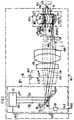
- Figure 1 shows a measuring device ME according to the invention as components, a transmission / coupling device SK with a optical transmitter OT1 together with the associated coupling device KV1 (see FIG. 2), a control device assigned to it ASV1, an optical receiver OR1 and an evaluation device AE1 has.
- These components can work together with a multi-splice device framed by dash-dotted lines MS1 conveniently to a measuring case e.g. an optical fiber splicer or one Attenuation meter be summarized.
- the invention can in addition to this particularly advantageous application also for the selective determination of further optical transmission parameters such as phase run times, impulse responses, Track damping, etc., as well as with a variety further problems of multi-fiber technology such as for fiber optic identification, for production control and production monitoring of fiber optic ribbon, for quality control, for determining fiber geometries and optical quality characteristics, etc. are used will.
- further optical transmission parameters such as phase run times, impulse responses, Track damping, etc.
- Figure 1 are in the multiple splicer MS1 a first ribbon cable BL1 (fiber optic ribbon) with optical fibers LW1 to LWn and a second, with it to be welded ribbon cable BL2 with optical fibers LW1 * to LWn * opposite.
- the fiber optic cable LW1 to LWn of the strip line BL1 are almost parallel in one flat, approximately rectangular in cross-section, outer covering AH1 (made of plastic material) embedded in the indicated on the left part of Figure 1 and in the remaining part of the figure omitted for the sake of clarity is.
- the optical fibers LW1 * bis LWn * of the strip line BL2 from a similarly trained outer envelope AH2 surrounded in the right part of figure 1 indicated and then omitted is.
- the outer wrappings AH1 and AH2 are at least partially optically transparent Material selected to ensure a largely and / or to ensure coupling of light.
- Coupling LW1 to LWn becomes the transmitting / coupling device SK to an arbitrarily definable section of the route the ribbon cable BL1 coupled in the left part of Figure 1.
- the optical fibers LW1 to LWn as can be seen from Figure 2, in the coupling device KV1 is approximately arched or curved.
- Bending mandrel ZT1 provided a bending coupler BK1.
- the bending coupler BK1 points to the lateral position securing or for guiding the ribbon cable BL1 on the circumference of its Cylinder ZT1 a guide groove FN1, the width of which the width of the ribbon cable or the Optical fiber ribbon corresponds to BL1.
- the optical transmitter OT1 has at least one transmission element TE on, for example a laser diode or a laser, that in the illustrated embodiment is almost parallel Beam or a parallel beam LB in the direction on a rotatable provided as a deflection device or swiveling mirror BS with a transmission power TP emits.
- 2 are for the sake of clarity only three of k light beams LS1 to LSk of the light beam LB drawn.
- the light bundle LB hits the in the optical transmitter OT1 tilted to the main radiation direction, rotatable mirror BS on. Of its mirrored The light rays LS1 to LSk are reflected on the surface VO and almost parallel to each other on a coupling optics EO, especially a lens system, between the optical transmitter OT1 and the coupling device KV1.
- the coupling optics EO bundles i.e. focused that Light rays LS1 to LSk to a transmit radiation field SF, whose light spot LF in a coupling area or curvature area KB1 of the bending coupler BK1 is shown.
- the coupling area KB1 in which the optical waveguide LW1 until LWn are curved, is dash-dotted in Figure 2 framed indicated.
- a coupling level is in this coupling area KB1 a y, z coordinate system.
- the of the y and The coupling plane spanned in the z-axis is approximately vertical to the plane of the drawing and thus perpendicular to the direction of propagation x of the respective transmission radiation field SF.
- the y axis indicates a scanning direction for the light spot or light spot LF transverse to the longitudinal direction (axial Extension) of the strip line BL1.
- the light spot LF shows in the coupling plane y, z preferably an almost strip-shaped one or linear or slim oval shape (cf. Figures 9 and 10).
- To generate the light spot LF can Mirrors expediently in the beam path of the light beam LB. or suitable diaphragms (e.g.
- a slit diaphragm as Mapping means are provided for the transmission radiation field SF be.
- the light spot LF in the z direction on Coupling location or in the coupling plane a spatial extension chosen, which is advantageously at least equal to half the thickness of the optical fiber ribbon BL1, in particular between 100 ⁇ m and 200 ⁇ m. It is generally sufficient an expansion of the light spot LF in the z direction at the coupling location in the order of the thickness of the optical waveguide or the thickness of the fiber optic ribbon BL1.
- the illumination field width of the light spot LF in the scanning direction y is preferably smaller at the coupling location selected as the optical fiber outer diameter (especially e.g. below about 250 ⁇ m), so that with high Light output Light in the respective fiber optic core can be coupled.
- the beam width of the light spot LF in the y direction should expediently at the coupling location at least equal to the core diameter of the respective Optical fiber can be selected, in particular if already an alignment of the transmitted radiation field on the respective fiber optic core at the coupling location and the transmitted radiation field at the respective coupling-in location is certain.
- the beam width of the light spot LF in the y direction is advantageous also smaller than the core diameter of each Optical fiber selected, so that the preferably linear Light spot LF during the beam movement over the Coupling location the core of the respective optical fiber continuously swept and illuminated. So that can Loss of radiation in the spaces between the fiber optic core largely avoided to fiber optic core will.
- the transmission radiation field SF expediently has an approximately elongated one at the coupling point in three dimensions Illumination field, whose spatial extent in z direction is greater than selected in the scanning direction y. More details on the spatial shape of the light spot LF are described in Figures 9 and 10.
- Figure 2 shows an inclined position of the rotatable mirror or deflecting mirror BS, in which the transmitted radiation field SF, for example, with its light spot or light spot LF a coupling section TC1 along the curved Optical fiber LW1 illuminated and almost tangential is coupled into its core.
- the respective Coupling section e.g. TC1 and thus the actual one Coupling location in the core of the respective optical fiber e.g. LW1 is expediently in the end area the curvature of the arcuate optical waveguide e.g. LW1 at the transition to its straight line Illuminated route section, so that radiation losses or an unwanted light decoupling due to largely curved course of the optical waveguide are avoided.
- the actual launch location for the light coupling is advantageously about one Angle of curvature of 8 degrees different from that Place along the curved optical fiber e.g. LW1 assigned at which the optical fiber from cylindrical bending mandrel ZT1 of the bending coupler BK1 lifts off and leaves it straight.
- Coupling section hit light spot LF e.g. TC1 to to a length of about 1 mm along the respective optical waveguide e.g. LW1.
- the illuminated coupling section TC1 is drawn with an approximately oval, dash-dotted line Outlined frame. In this coupling position Transmitting radiation field SF with its light spot LF only the optical waveguide LW1 in a clear manner Individual radiation field SF1 with a light spot LF1 assigned.
- the tilted deflection mirror BS is now in the beam path of the light beam LB by means of an actuating device BV twisted or tilted around its pivot point DP, i.e. its angle to the light rays LS1 to LS3 changed.
- the actuating device BV (see FIG. 1) is controlled by a control device ASV1 by means of a Control signal AS2 operated via a control line AL2.
- the actuation of the actuating device BV takes place as an example in such a way that the deflecting mirror BS starts out from its coupling position for the optical fiber LW1 continuous or steady at least up to one dash-dot Coupling position BS * shown for the optical waveguide LWn is twisted.
- the rotation of the mirror BS around the pivot point DP in the beam path of the light beam LB is symbolically indicated by an arrow V. Due to the constant rotating movement of the mirror BS the light beams LS1 to LS3 are deflected or pivoted and mapped by the coupling optics EO in such a way that you Associated transmit radiation field SF the coupling or curvature area KB1 sweeps linearly one after the other or illuminated. A screened, i.e. gradually, turning the deflecting mirror BS be so that the transmit radiation field SF with its light spot LF gradually, i.e. gradually, the coupling area KB1 scans.
- the scanning steps are expediently light spot LF equal to or less than the distance between two adjacent fiber optic cores chosen.
- the transmission radiation field SF moves translationally parallel to the plane in which the Optical fibers LW1 to LWn lie, i.e. it goes through or scanned one after the other with its light spot LF the entire coupling area KB1 in the scanning direction y.
- the change in angle caused by the rotatable mirror BS is thus a linear displacement of the light spot LF implemented in the y direction.
- the transmission radiation field SF migrates with its light spot LF, for example in the case of optical fibers LW1 starting steadily or gradually over the coupling area KB1 in the y direction on the optical waveguide LWn closed, i.e. vividly in Figure 2:
- the transmit radiation field SF gropes due to the rotating movement of the deflecting mirror BS transverse to the axial extension of the curved Optical fibers LW1 to LWn from bottom to top via the coupling area KB1.
- the upper coupling position of the Transmitted radiation field SF is shown by means of dash-dotted lines
- Light rays LS1 * to LSk * illustrates which are assigned to the twisted deflection mirror BS *.
- the transmit radiation field SF * with its light spot LF * is used as one individually assigned to the fiber optic cable LWn Transmitted radiation field SFn with associated light spot LFn almost tangentially coupled into its core.
- the light spot LF of the transmitted radiation field SF sequentially during its movement in the scanning direction y preferably only in one of the optical fiber cores coupled and not in several. Every optical fiber LW1 to LWn is therefore uniquely on Transmitting radiation field SF1 to SFn, each with an individual one Light spot LF1 to LFn assigned to the curved guided optical fibers LW1 to LWn along associated Coupling sections TC1 to TCn are illuminated.
- the axis of rotation of the mirror BS on the one hand and the coupling areas TC1 to TCn on the other hand are expedient each in the focal points of the coupling optics EO arranged to be as focused as possible Achieve high power light coupling.
- a rotating one can also be used Mirrors can be used.
- Beam deflection system with a linearly movable mirror or a movement of the transmitting element itself, which requires an appropriately adapted coupling optics EO.
- a beam blanking device for example a continuous one Slit diaphragm can be used.
- drive elements suitable for actuating the beam deflection device e.g. Self-resonance scanner (torsion bar scanner, torsion band scanner), Galvanometer scanner, piezoelectric Scanners, etc. While natural resonance scanners have a fixed frequency have, is in galvanometer scanners and piezoelectric Scanners the frequency variable.
- the drive elements continue to differ in the wave patterns, with which a scan is possible. Can be advantageous possible malfunctions of the mechanical beam deflection device also by using an acousto / electro-optical Deflection element can be avoided.
- the measurement signals I1 to In can also be direct over the open ends of the optical fibers LW1 to LWn are fed into their cores if they are accessible are.
- the measurement signals I1 to In can advantageously in Figure 1 from a dedicated transmitter, such as originate from the transmission element TE, but also message signals from the optical fibers LW1 to LWn.
- optical Transmitter OT1 can be advantageous for selective, distinguishable Coupling of the measurement signals I1 to In also several Transmitting elements may be provided, preferably in the form a line or an array (transmitter field) combined are. A selective measurement signal coupling can then advantageous by controlling these transmission elements by means of the control device ASV1 in multiplex mode can be achieved.
- the number of Transmission elements in relation to the number of to be measured Optical fibers LW1 to LWn the larger the number of Sending elements is selected, the greater the achievable temporal resolution, i.e. the closer it is to the continuous or steady light coupling of Figure 2.
- the achievable temporal resolution i.e. the closer it is to the continuous or steady light coupling of Figure 2.
- at least as many transmission elements are provided how to measure optical fibers. Generally enough about two to four times as many transmission elements.
- a second coupling device KV2 (constructed analogously to the coupling device KV1) from the optical receiver OR1 e.g. by means of a second Bend coupler BK2 coupled out in approximately tangential direction.
- the optical fibers LW1 * to LWn * of the second ribbon cable BL2 are in a guide groove FN2 by one
- the cylinder ZT2 is bent around analogously to the transmission side.
- the transmitted radiation fields SF1 to SFn assigned receive radiation fields RF1 to RFn that each individually the optical fibers to be measured LW1 to LWn are assigned, from their cores along arcuate Coupling sections RC1 to RCn in the coupling area KB2 of the bending coupler BK2. Because through the Shifting movement of the light spot LF one after the other in time the measurement signals I1 to In selectively in the cores of the Optical fibers LW1 to LWn are caused to appear also their assigned receive radiation fields RF1 to RFn in corresponding chronological order, i.e. here: The received radiation field RF1 for the optical fiber LW1 is received first.
- the received radiation fields RF1 to RFn are sequential, i.e. sequential, from a common, preferably fixed arranged, light-sensitive element GLE at least partially recorded or recorded and by this in each case converted into an electrical measurement signal DS2.
- the signal DS2 is evaluated via a signal line DL2 to a digitizer SUH of an evaluation device AE1 transmitted.
- This digitizer SUH gropes the electrical arrives one after the other Measurement signals DS2 from short intervals, digitized these samples and transmits digitized measurement signals DS3 via a line DL3 to a measured value memory MEM in the evaluation device AE1. From this measured value memory MEM become the recorded, digitized measurement data via a line DL5 as a signal DS5 to a display device DSP1, e.g. a display, forwarded and visualized there.
- a display device DSP1 e.g. a display
- a large-area receiving element GLE that covers all optical fibers to be measured, it is not required at the receiving end, e.g. the receiving element GLE for a selective, distinguishable recording of the Receive radiation fields RF1 to RFn corresponding to Optical fiber LW1 activated one after the other to move LWn.
- An individual alignment of the Receiving element GLE on the activated optical fiber is therefore not applicable. Nevertheless, it can if necessary for a further spatial resolution of the received radiation fields RF1 to RFn can also be beneficial to several Receiving elements, especially in line or array form instead of the common receiving element GLE, preferably fixed to attach.
- Suitable as receiving elements e.g. conventional photodiodes, CCD elements, diode arrays, Diode rows, etc.
- the transmitting radiation field SF can have a purpose on the transmitting side
- Have transmission level TP of any predetermined shows the course over time.
- the transmission side with an approximately constant in time Transmission level operated CTP i.e. during the light spot LF travels over the coupling area KB1 of the bending coupler BK1, illuminates the associated coupling sections TC1 to TCn along the curved optical fibers LW1 to LWn with an almost constant transmission power or an almost constant transmission level CTP.
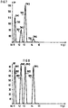
- the one in figure 3 shows a time-constant intensity and power distribution TP for the transmit radiation field SF during its displacement movement starting with the optical fiber LW1 at time tA something about the optical fiber LWn beyond the time required up to the time tE Shift time t continuously recorded.
- the displacement time t corresponds to the displacement path y.
- the light spot LF traverses the time period tE-tA the coupling area K61, so that the coupling sections TC1 to TCn by the individual assigned to them
- Light spots LF1 to LFn with a constant time Illumination field strength of approximately CTP 7.5 E (1E ⁇ 1 light unit) be irradiated.
- the LW1 to LWn individually assigned, i.e. effective for them effective, transmit radiation fields SF1 to SFn that is, a constant transmission level in the shift time interval tE-tA on.
- the optical receiver OR1 At the receiving end (see FIG. 4) is in the optical receiver OR1 in turn for the received radiation fields RF1 to RFn an associated temporal intensity or power distribution, i.e. temporal distribution, RP during the duration tE-tA added, as in the sequential coupling of the transmission radiation field SF on the transmission side or the individually assigned transmit radiation fields SF1 to SFn is created.
- the displacement movement of the light spot LF corresponds to the temporal distribution RP of the received radiation fields RF1 to RFn approximately the local position of the optical fibers, especially the fiber optic cores.
- the selective reception level RH1 to RH4 set with digital Signal evaluation in each case envelope or interpolated for the digitized, sampled measurement signals, i.e. they correspond to the temporal distribution of the received radiation fields RF1 to RF4 for the case of a continuous or continuous transmission coupling.
- the different highs RM1 to RM4 as well as the non-equidistant location of the benefit or Reception level RH1 to RH4 can have different causes:
- the coupling factors on the transmission side, on the Alignment point in the MS1 multiple splicer, as well as on the receiving side for each individual to be measured Fiber optics individually different from each other be.
- different colors the optical waveguide in the ribbon cable BL1 or BL2 as e.g. red, green, yellow, blue or different thicknesses of paint as well as different coatings different coupling factors, i.e. different Coupling and decoupling attenuation for each optical fiber, have as a consequence.
- Differences in the coupling factors can also arise, for example, that Optical fibers from different manufacturing or Drawing process batches and thus, if necessary, from each other various light-guiding properties and fiber geometries combined into an optical fiber ribbon will.
- the coupling conditions are also through the positional tolerances of the optical fibers in the curvatures affects the bending coupler.
- the level differences or Level fluctuations (typically 10 dB) would be received in the optical receiver OR1 from optical fiber Different reinforcements necessary do. Switching to individual gain factors for each individual optical fiber would therefore be one additional, high electronic and temporal Mean effort. It would also change due to the fluctuations the reception level or the temporal distribution RP on the receiver side only a relatively bad signal / / Noise ratio result because an optimal control only for one of the fiber optic combinations can be carried out and transmission side due to the low Dimensions of the fiber optic core usually only relatively small light outputs in the fiber optic cores can be coupled in and guided there.
- the time distribution RP is also through the local position of the optical fibers LW1 to LW4 in the stripline BL1 or by the local location of the Optical wave curtain LW1 * to LW4 * in the ribbon cable BL2 and by assigning them to each other in the multiple splicer MS1 affected.
- the temporal Distribution RP of the received radiation fields RF1 to RFn e.g. by means of a computing unit CPU in the evaluation device AE1 of Figure 1 evaluated and for subsequent actual measurements for optimal coupling on the transmission side recycled.
- This is the processing unit at the receiving end CPU with the transmitter-side control device ASV1 for the Transmitter / coupling device SK connected via a line SL3, i.e. the sending side is to a certain extent with the receiving side "fed back" (see FIG. 1).
- the control device ASV1 receives control signals SS3 via the line SL3 from the CPU, puts them in control signals AS1 and thus controls the optical transmitter OT1, preferably whose transmission element TE, via a line AL1.
- the invention Process especially for optimizing the individual, selective coupling performance for everyone too measuring optical fiber, in particular in an optical fiber ribbon be used.
- This will do so achieved that initially in at least one reference measurement or in a kind of calibration process any transmission level each coupled into the optical waveguide to be measured and on the receiving side the characteristic temporal distribution of the associated received radiation fields is recorded and held. From this temporal Distribution can have different criteria for tax purposes Criteria for controlling the coupling-in light spot on the transmission side, such as. his lighting field strength, his Size and shape, its switch-on and / or switch-off times, etc. can be determined.
- the control of the light spot LF can also form a control loop be supplemented, their reel sizes in an analogous manner to Figures 1 to 8 determined from the temporal distribution and be provided.
- the control device for the transmission / coupling device SK then expediently a control circuit with internal feedback on.
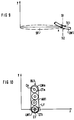
- FIG. 9 illustrates the spatial shape of the light spot LF.
- FIG. 9 is analogous to FIG. 2 a scan plane with the coordinate axes x and y fixed.
- the x-axis indicates the direction of the beam or direction of propagation of the transmitted radiation field SF.
- the y-axis points in the scanning or displacement direction of the transmitted radiation field SF transverse to the longitudinal axis of the measuring optical fiber LW1 to LWn in the coupling area KB1.
- Figure 9 there is only one curved one for illustration Part of the optical waveguide LW1 drawn in, while the remaining LW2 until LWn have been omitted.
- the transmit radiation field SF in this drawing plane in a schematic way is indicated by dash-dotted lines, occurs with its light spot almost tangentially into the core of the curved Optical fiber LW1 at the coupling location in the area of Dash-in drawn-in coupling section TC1 focused one.
- the coupling section TC1 is thereby expediently up to about 1 mm along the optical waveguide LW1 illuminated by the light spot. Possibly the light spot can also directly touch the open end e.g. of the fiber optic cable LW1, if this is accessible.
- Figure 10 shows a schematic view of the light spot together with the ribbon cable BL1 in a cutting plane, which is obtained by cutting perpendicular to the plane of the drawing Figure 9 along the section line S1, S2 at the coupling location of the transmitted radiation field SF in the optical waveguide LW1 receives.
- Figure 10 represents there for better illustration the spatial shape of the light spot LF one imaginary coupling plane with the coordinate axes y and z perpendicular to the direction of propagation or beam x of the transmitted radiation field SF.
- the optical fibers LW1 bis LWn have different diameters from and are combined in the strip line BL1.
- the cores C1 to Cn of the optical fibers LW1 to LWn are at the respective Coupling point not exactly along a straight line arranged parallel to the scanning direction y, but lie somewhat offset from each other in different spatial positions the outer sheath AH1 of the ribbon cable BL1.
- the cores C1 to Cn may also point in the scanning direction y non-equidistant distances from each other.
- Cause of those in the z and / or in the y direction from the ideal distribution deviating positioning of the cores can e.g. be that the cores C1 to Cn each in their outer coating envelope (Coating) CT1 to CTn eccentric, i.e. not centred (e.g.
- Figure 10 is LF for the light spot in the coupling plane y, z advantageous at the coupling-in location of the optical waveguide LW1 e.g. an approximately slim oval or elliptical, approximately strip-shaped or linear cross-sectional shape with alignment of its longitudinal axis in the z direction chosen.
- the light spot LF is therefore uneven Cross-sectional shape that is vertical at the coupling location a preferred direction in the z direction to the direction of propagation x shows. Its spatial extension in the z direction, that is, perpendicular to the direction of propagation x, is advantageous larger than selected in the scan or scanning direction y.
- the transmission radiation field SF is, for example, in FIG.
- the optical fiber LW1 aligned so that the associated light spot LF the Core C1 approximately symmetrical to its center illuminated. It has a spatial extension in the z direction which ensures that the cores C1 to Cn even with an arrangement in different z-spatial positions in of the strip line BL1 through the light spot LF in the y direction migrating transmitted radiation field SF and be reliably illuminated in the z direction.
- the spatial Extension of the light spot LF in the z direction at the coupling location is expediently chosen so that expected Positional tolerances of the fiber optic cores Cl to Cn, the especially different due to the use thick ribbon can come about in the bending coupler BK1, are balanced.
- the light spot has LF in the z direction expediently at the coupling location spatial extent that is at least half the fiber optic ribbon thickness or about half the outer diameter of the respective optical fiber, preferably between 100 ⁇ m and 200 ⁇ m.
- Optical fiber ribbon or with optical fibers with the outer diameter becomes the length of the light spot LF in the z direction is appropriately larger. It is generally sufficient to extend the Light spots LF in the z direction at the coupling location in the order of magnitude of the thickness or outer diameter of the respective Optical waveguide or the respective thickness of the Optical fiber ribbon BL1.
- the longitudinal extension of the Light spot LF is thus expediently such in each case adjusted in the z-direction that during the scanning movement of the transmitted radiation field SF a focused coupling into the cores C1 to Cn of the optical fibers LW1 to LWn largely ensured with the LF light spot is when the nuclei C1 to Cn differ in the z direction Positions or positions at the coupling location Take BL1 in the ribbon cable.
- the launch time intervals for a selective launch of measurement signals in cases I. and II largely through the response times or settling times of the elements in the optical receiver OR1 (e.g. the common photosensitive element GLE) and / or in the receiving device AE1 (e.g. the digitizing element SUH) determined.
- the optical receiver OR1 e.g. the common photosensitive element GLE
- the receiving device AE1 e.g. the digitizing element SUH
- the receiving end Evaluation of the provided temporal distribution of the Receiving radiation fields of several optical fibers to be measured may be difficult. For example it can be due to receiver noise at the receiving end Measurement inaccuracies from the received radiation fields generated received signals come. Furthermore, e.g. slight irregularities in the movement of the transmission side Transmitting radiation field on the receiving side to fluctuations in the temporal position of the received radiation fields lead, especially in multiple runs (Multiple scans) of the transmitted radiation field, i.e. a kind of Cause "jitter effect".
- a further development of the invention is therefore the task based on showing a way like the evaluation the provided temporal distribution of the received radiation fields several optical fibers to be measured can be easily improved.
- This task is solved in that in at least a first pass through the transmission radiation field temporal distribution of the received radiation fields registered and is held, and that because of this Registration for subsequent measurements at the receiving end Control processes are triggered.
- This further training is characterized above all by that first in a first broadcast-side pass of the Transmit radiation field the temporal distribution of the Receiving radiation fields of the optical fibers to be measured registered and recorded. Only then will based on this registration control operations at the receiving end triggered for subsequent, actual measurements. With the help of the first transmission-side pass can thus first of all essential measurement information the optical fibers to be measured are obtained and thus the coupling conditions on the transmitting and / or receiving side for the actual, subsequent measurements in a defined Way to be set. This is in subsequent Measurements a largely exact evaluation of the provided abundance of measurement information from the temporal Distribution of the received radiation fields in a simple and reproducible manner.
- the received radiation fields be registered and then in at least a second Transit-side pass the measured received signals of the received radiation fields in each case over these time slots be integrated away. Stand this way the light outputs of the received radiation fields for further Evaluation available, especially for control the transmission power of the transmission radiation field individually for each optical fiber to be measured.
- a further development of the invention also relates to a device for measurements on several optical fibers with an optical transmission / coupling device, which to each optical fiber to be measured can be coupled, and with an optical receiver that has at least one Receiving element has an evaluation device is assigned, the transmission / coupling device in this way is formed that a transmission radiation field on the transmission side with its light spot over coupling sections of the optical fibers to be measured one after the other in time is movable and can be coupled into it, and in the optical Receiver aligned the receiving element and is formed that this is the transmission side Coupling assigned reception radiation fields of the Optical fiber to be measured in its temporal distribution detected, received signals generated therefrom, and this feeds an evaluation device, which is characterized is that the evaluation device is a computing unit with the associated measured value memory, that the in at least a first transmission side Passage of the transmitted radiation field generated reception signals registrable and based on this registration in subsequent measurements, control operations at the receiving end can be triggered by control means.
- FIG. 11 shows a preferred embodiment of the invention Measuring device ME of Fig. 1.
- the optical one Transmitter and the coupling device are dash-dotted in the indicated frame of the transmission / coupling device SK has been omitted for the sake of clarity.
- These components can be dotted along with the framed multiple splicer MS1 expediently to a measuring case, e.g. an optical fiber splicer or a damping measuring device, summarized be.
- the invention can be particularly advantageous Area of application also for selective determination other optical transmission parameters such as Phase delays, impulse responses, path attenuation, etc., as well as with a variety of other problems multi-fiber technology such as for fiber optic identification, for production control and production monitoring of fiber optic ribbon, for quality control, for the determination of fiber geometries and optical Quality properties, etc. are used.
- multi-fiber technology such as for fiber optic identification, for production control and production monitoring of fiber optic ribbon, for quality control, for the determination of fiber geometries and optical Quality properties, etc. are used.
- Figure 11 are in the multiple splicer MS1 the first ribbon cable BL1 (fiber optic ribbon) with the optical fibers LW1 to LWn and the second, strip line BL2 to be welded to it with the Optical fibers LW1 * to LWn * opposite.
- the optical fibers LW1 to LWn of the ribbon cable BL1 are almost parallel in a flat, approximately rectangular in cross section, outer casing AH1 (made of plastic material) embedded, which is indicated in the left part of Figure 11 and in the rest of the figure for the sake of clarity has been omitted.
- the optical fibers are corresponding to this LW1 * to LWn * of the ribbon cable BL2 from one similarly formed outer envelope AH2, which shown in the right part of Figure 11 and then left out.
- the outer envelopes AH1 and AH2 at least partially optically transparent material chosen to a large extent low-loss coupling and / or coupling of light to ensure.
- the transmission / coupling device SK expediently, for example, a coupling device according to the bending coupler principle.
- the optical fibers LW1 to LWn advantageous each along an arbitrarily definable section of the route approximately arcuate or curved around an approximately cylindrical Bending mandrel of a bending coupler.
- the coupling device with the bending coupler is dash-dotted in the framed transmission / coupling device SK by Figure 11 has been omitted for clarity.
- a transmission side Light coupling is also in the open end faces the optical fiber to be measured with free Accessibility of the ends appropriate.
- the optical transmitter of the transmission / coupling device SK has expediently, for example, at least one transmission element on, for example a laser diode or a laser.
- This transmission element sends a transmission radiation field in Direction towards a beam deflector, such as a rotating mirror.
- a beam deflector such as a rotating mirror.
- This rotating mirror is advantageous using a galvanometer scanner transverse to the main radiation direction of the transmitted radiation field rotated or tilted. This will make the transmit radiation field with its light spot one after the other via coupling sections of the optical fibers to be measured moves, so that measurement signals I1 to In in the to be measured Optical fibers LW1 to LWn one after the other in time be coupled.
- a second Coupling device KV2 (constructed analogously to the transmission side Coupling device) from the optical receiver OR1 e.g. by means of a second bending coupler BK2 approximately tangential Decoupled direction.
- the optical fibers LW1 * to LWn * of the second ribbon cable BL2 are in a guide groove FN2 around a cylinder ZT2 (analogous to Transmission side) bent around.
- each individually assigned to the optical fibers LW1 to LWn to be measured are, from the cores along preferably arcuate Coupling sections RC1 to RCn in the coupling area KB2 of the bending coupler BK2. Because of the shifting movement of the transmission-side light spot over the coupling sections the optical waveguide LW1 to LWn successively in time the measurement signals I1 to In selectively in the cores the optical fibers LW1 to LWn are caused, their assigned receive radiation fields also appear RF1 to RFn in corresponding chronological order, i.e. here:
- the received radiation field RF1 for the optical waveguide LW1 is received first. Then follow the The reception radiation fields RF2 to RFn - 1 in sequence, until finally the LWn assigned received radiation field RFn in the coupling area KB2 arrives and exits there.
- the received radiation fields RF1 to RFn are sequential, i.e. sequential, from a common, preferably fixed arranged, light-sensitive element GLE at least partially recorded or recorded and by this in each case converted into an electrical measurement signal DS2.
- the measurement signal DS2 is over a signal line DL2 directly to a digitizer SUH transmitted to an evaluation device AE1.
- This digitizer SUH gropes those that arrive one after the other electrical measuring signals DS2 at short intervals, digitizes these samples and transmits digitized Measuring signals DS3 via a line DL3 to a measured value memory MEM of the evaluation device AE1. From this measured value memory MEM are the recorded, digitized Measurement data over a line DL5 as a signal DS5 to a display device DSP1, e.g. a display and visualized there.
- a computing unit CPU takes the recorded time Distribution of the received radiation fields RF1 - RFn over a line DL4 as signal DS4 from the measured value memory MEM and evaluates the measurement information.
- a large-area receiving element GLE such as. a photodiode that contains all optical fibers to be measured detected
- the receiving element GLE it is not necessary at the receiving end, e.g. the receiving element GLE for a selective, distinguishable recording of the received radiation fields RF1 to RFn correspond to those activated one after the other Optical fiber LW1 to LWn shift.
- a individual alignment of the receiving element GLE on the each activated optical waveguide as with a small area Receiving element, each with only one optical fiber recorded, is therefore omitted.
- It can also if necessary for a further spatial resolution of the received radiation fields RF1 to RFn can be beneficial to several Receiving elements, especially in line or array form instead of the common receiving element GLE, preferably fixed to attach.
- Suitable as receiving elements e.g. conventional photodiodes, CCD elements, diode arrays Diode rows, etc.
- the receiving end Optical fiber LW1 * to LW11 * with at least one first transmission-side pass of the transmission radiation field carried out.
- the temporal distribution the received radiation fields RF1 to RFn (the optical fiber combinations LW1 / LW1 * bis LW11 / LW11 *) during record this first broadcast-side pass can, is in the optical receiver OR1 in line DL2 a switch SW brought into such a switch position, that each receive signal DS2 of the successively arriving Receive radiation fields RF1 to RFn directly the evaluation device AE1 is switched through.
- the selective reception levels RH1 to RH4 provide envelopes for digital signal evaluation or interpolated for the digitized, sampled Measurement signals, i.e. they correspond to the temporal Distribution of the received radiation fields RF1 to RF4 for the case of a continuous or steady transmission side Coupling. For example, it surrounds the optical waveguide Receive level RH1 assigned to LW1 three discrete, dash-dotted, received values DP1, DP2 and DP3.
- the four envelopes or reception levels RH1 to RH4 differ in their temporal position (time position), i.e. in their temporal position to each other. It will therefore not at all times t in the time interval tE - tA during the first pass of the transmission radiation field on the transmission side Light into the cores of the measured Optical fiber LW1 to LW4 coupled in and guided there, but only at the times when the Coupling device (transmitter coupler) SK the light spot one Fiber or fiber optic core meets. So it will Light output in the fiber optic cores only to be determined Coupling times as well as at certain time intervals guided.
- the coupling-in times of the transmission radiation field on the transmission side are therefore during at least one first pass on the transmission side on the receiving side Time slots of the received radiation fields RF1 to RF4 or whose associated reception level RH1 to RH4 is determined.
- the respective for the respective reception level Time of its rising level edge and / or the Time of its falling level edge using the Computing unit CPU of the evaluation device AE1 determines and captured.
- the times t1, t2, t3 and t4 increase Level edges thus identify those coupling times from which light actually enters the cores of the optical fibers LW1 to LW4 is coupled.
- the times t1 *, t2 *, t3 * and t4 * on the other hand, set those times (Dead times), from which there is no light in the core of the Optical fiber LW1 to LW4 is guided.
- the time slots t1 to t1 *, t2 to t2 *, t3 to t3 * and t4 to t4 * der Receiving levels RH1 to RH4 thus characterize the temporal Sequence and the duration of the actual lighting in the optical fiber combinations LW1 / to be measured LW1 * to LW4 / LW4 *.
- the computing unit at the receiving end transmits CPU of the evaluation device AE1 this time frame, i.e. the times (t1 / t1 * to t4 / t4 *) of those from the first transmission side Pass received level RH1 to RH4, by means of control signals SS3 via the line SL3 to the Control device ASV1 of the transmission / coupling device SK on the sending side.
- the control device ASV1 sets these control signals SS3 to control signals AS1 and thus preferably controls the optical transmission element Transmitter via a line AL1 according to the predetermined Time frame preferably in a kind of "pulse mode".
- the transmission element is therefore in accordance with the predetermined Time frames at times t1, t2, t3 and t4 activated and at times t1 *, t2 *, t3 * and t4 * deactivated.
- the pulse mode can also advantageously be realized in this way that the beam deflecting device of the transmitting / coupling device SK, for example a deflection mirror with a Galvanometer scanner as drive element by leaps and bounds (step by step) is twisted so that the fiber optic cores only during the transmission times t1 to t1 *, t2 to t2 *, t3 to t3 * and t4 to t4 * with the light spot of the transmitted radiation field are keyed or swiped.
- the beam deflecting device of the transmitting / coupling device SK for example a deflection mirror with a Galvanometer scanner as drive element by leaps and bounds (step by step) is twisted so that the fiber optic cores only during the transmission times t1 to t1 *, t2 to t2 *, t3 to t3 * and t4 to t4 * with the light spot of the transmitted radiation field are keyed or swiped.
- the light spot is continuously coated with the light spot. This means that the requirements for portioning accuracy are required of the light spot on the fiber cores advantageous not to be particularly high.
- the light spot can be triggered as a control process at the receiving end expediently also only to the individual, the motor positions associated with Maxima RM1 to RM4 can be set so that only the maximum value of the Power level is measured at the receiving end. This offers the advantage of improved utilization of the transmission element, a simpler evaluation at the receiving end (only in each case 1 measured value per reception level), but requires one higher position accuracy in order to be reproducible To get measurements. Additional ones are then expedient Control elements for the drive element of the movable Provide a mirror that is controlled, gradual Allow (sudden) deflection of the mirror.
- the reception level RH1 to RH4 of the received radiation fields RF1 through RF4 are now shown in Figure 11 based on this registration in subsequent measurements, control operations at the receiving end triggered.
- the switch SW becomes the reception radiation fields RF1 to RF4 in the optical receiver OR1 of Figure 11 by means of the computing unit CPU via a control line SWL according to the given time frame (with the determined time slots) from the 1st measurement, i.e. according to the chronological order the received radiation fields detected by the light-sensitive element GLE, between two positions P1 and P2 switched.
- the switch SW takes the position P1.
- the evaluation device AE1 still get to the integrator INT, i.e. the desk SW couples the optical receiver in position P1 OR1 from the evaluation device AE1, i.e. he is yourself in the "air".
- the switch SW is called the receiving side Triggering means for the integrator INT according to the time Sequence of the previously registered received radiation fields, i.e. in sync with their times, between the two positions P1 and P2 switched back and forth.
- the integrator INT as receiving-side control means only during the respective transmission duration e.g. from t1 to t1 * the incoming Received signal DS2 integrated.
- the integrator INT thus selectively determines the respective total light output of the current reception radiation field and passes this summed measurement value to the Evaluation device AE1 for further evaluation.
- the integrator INT via a control line RS from the computing unit CPU Reset to zero and the measuring process for the next received radiation field repeated.
- the integrator INT approximately in the middle between two adjacent time slots, e.g. between the two time slots t1 to t1 * and t2 to t2 *, i.e. in the middle between two levels such as RH1 and RH2, read out and be reset.
- the receiving end for each individual fiber optic individually a gain factor can be set so that each one optimal control of the integrator INT and the subsequent ones Signal evaluation (SUH) results, preferably thus can achieve a level adjustment at the receiving end.
- a transmission-side performance adjustment to compensate for the Level fluctuations at the receiving end can then possibly be omitted.
- an improvement in the signal / Noise ratio as with the transmission side not Power adjustment through switching or amplification be effected.
- decoupling optics AO may be provided, the dash-dotted line in Figure 1 between the coupling device KV2 and the light-sensitive element GLE is.
- the coupling optics can be expediently AO by means of the CPU according to the temporal sequence from the first measuring process as another control process on the receiving side individually for everyone measuring optical fiber over a not shown here Set the signal line.
- decoupling optics AO is preferably suitable e.g. a spherical lens.
- each only one radiation field to be measured detects, also be appropriate, this small-area receiving element as the receiving-side control process due to the Registration of the time slots from the first transmission side Pass according to this time distribution move.
- the time distribution RP of the first measurement process also information for the control of Actuators SG1, SG2 according to the multiple splice MS1 Figure 11 win.
- a relative measurement is expediently used for this purpose performed in each fiber optic is initially aimed at maximum transmission and then the associated level is used as a reference value.
- From Figure 14 or from the display image of the display device DSP1 of Figure 11 shows that that of the fiber optic combination Received radiation field assigned to LW3 / LWS3 RF3 the relative reception level RH3 with the has the lowest maximum RM3.
- the fiber optic Received radiation field RF4 assigned to LW4 however, the highest relative reception level RH4 within the group of four optical fibers to be measured LW1 to LW4 on.
- Control lines SL1, SL2 can be used by means of control signals SS1, SS2, the actuators SG1 and Operate SG2 from the CPU. Let it through the two tapes BL1 and BL2 are preferably such shift against each other that for all measured Reception level RH1 to RH4 together or simultaneously a maximum relative reception level before each Splicing process results.
- the first Registration of the temporal distribution of the reception level also expediently the control of the splice or Welding process for the two to be joined together Ribbon BL1 and BL2 are triggered.
- the controls Processing unit CPU the welding time so that for all fiber optic cable combinations to be connected LW1 / LW1 * to LW4 / LW4 * viewed together at the receiving end, i.e. at the same time the maximum possible reception level results.
- the measuring device ME works particularly advantageously Figure 11 with a periodic deflection of the light beam of the transmission radiation field on the transmission side by one to enable quasi-continuous measurement.
- This periodic Distraction can be achieved, for example, that a tiltable mirror as a beam deflecting device in the transmission / coupling device SK by a galvanometer scanner periodically back and forth.
- This movement of the mirror is due to its mass moment of inertia sinusoidal, i.e. his angle of rotation depends sinusoidally on the time t. So it is around a non-linear scanning movement of the transmission beam.
- FIG. 12 shows the sinusoidal curve SIN of the angle of rotation depending on the time t.
- the mirror rotation is expediently with the help of an optical Systems, such as a ball lens in the transmitter / coupler SK in an angle-proportional deflection of the light spot of the transmitted radiation field from the Center position implemented so that the position of the light spot on the ribbon during the transmission-side pass as well depends sinusoidally on time.
- an optical Systems such as a ball lens in the transmitter / coupler SK in an angle-proportional deflection of the light spot of the transmitted radiation field from the Center position implemented so that the position of the light spot on the ribbon during the transmission-side pass as well depends sinusoidally on time.
- a fixed time Assignment i.e. a defined relationship between the transmission side coupling and the receiving side
- the control of the Scanner movement directly through the CPU in the CPU Evaluation device AE1, preferably by a processor. This allows a fixed time assignment all control and measurement processes in the measuring device ME from Figure 11 reach the current position of
- the Processor for example, a time grid of 50 microseconds. Out a square wave signal is generated in this time grid the level changes every 512 grid points of the time grid. So a period of the time grid has 1024 grid points, which corresponds to a frequency of approximately 20 Hz.
- the period of 1024 raster points is in the processor with a time raster counter, that counts from 0 to 1023 and then goes back to 0 to begin with, counted.
- From the 20 Hz square wave is in the scanner control ASV1 by analog filtering the desired sinusoidal control signal AS2 for the Scanner won.
- each Raster point reproducibly a specific location of the light spot corresponds in the transmission coupling device SK.
- the Time grid is in Figure 12 to illustrate the assignment between the grid points of the time grid counter and the sinusoidal scanner or light spot movement plotted below the time axis t and labeled RZ.
- the Light spot or light spot periodically with sinusoidal Time dependence on the optical fiber ribbon to be measured directed. At those times, too where it hits a fiber core, light is injected there. This measuring light is on the receiver side decoupled again and generated over time of the receiver output signal an associated, specific Reception level. Such a selective reception level arises every time the core of one to be measured Optical waveguide hit by the light spot on the transmission side because of the sinusoidal light spot movement twice per fiber and period. To essentially to use the linear part of the sinus movement and all optical fibers to be measured with the light spot The amplitude is sure to be overwritten on the transmission side the beam deflection is expediently chosen to be greater than the width of the optical fiber ribbon to be measured.
- FIG. 13 shows a temporal Distribution RP1 e.g. for four optical fibers to be measured of the two tapes according to FIG. 11 in the case of nonlinear Movement of the transmitted radiation field.
- the four levels of The first group are the jet return RL (first Half wave of the sine function), the second group, however the beam trace HL (second half wave of the sine function) assigned to Figure 12.
- Any reception level can clearly one of the four optical fibers assign in the ribbon to be measured, with the return the reception level of the optical fiber to be measured in reverse order appear.
- the receiver output signal to recognize the individual fiber cores of the optical fibers as well as from the height and / or area of the reception level to the relative, via the splice MS1 to close the light power transmitted from FIG. 11, are in the present exemplary embodiment expediently carried out the following two measuring processes:
- this is preferably constant Transmit power operated.
- the digitizer SUH the received signals generated DS2 per grid point, i.e. in the example every 50 ⁇ sec and digitizes the sample value obtained in this way in the measured value memory assigned to the computing unit CPU MEM.
- the processor's time slot counter delivers this preferably the memory address for each Sample. This process continues throughout Hinlaufs HL, in the embodiment for 512 raster points, repeated, leaving 512 samples in memory MEM stand for a run. These represent 512 samples the time course of the receiver output signal. Because of the temporally equidistant sampling the position of the samples in the memory (memory address) currently.
- the processor can also be any memory address a location of the light spot in the coupling area of the transmitting / coupling device Assign SK, although it is a nonlinear transmitting scanning movement. Conveniently the number of samples will be significantly higher than selected the number of optical fibers to be measured, so that associated with each reception level each Samples are dropped.
- Figure 15 shows the time distribution RP1 of the envelopes EH3 and EH4 of the samples for the reception level of the optical fibers 3 and 4 Figure 13 in an enlarged representation over the time grid RZ. The timings of these two envelopes EH3 and EH4 are determined by means of the evaluation device AE1.
- Envelope EH3 will be the time between its rising and its falling flank, i.e. between the Assigned times at3 and at3 *.
- the envelope EH4 accordingly shows its time position between the times at4 and at4 *.
- these are the times at which the envelopes start and end by means of the CPU saved.
- Addresses of the samples in memory MEM to which the the respective envelope begins and ends, is saved. These addresses correspond to the associated meter reading of the time slot counter of the CPU.
- a time sequence with time periods is defined, to which is sent, for example between at3 and at3 * and for which a pause is made, for Example between at3 * and at4.
- the transmitter side at least one pass through the transmission / radiation field carried out.
- a quasi-continuous recording of measured values is a periodic scan of the transmitted radiation field expedient.
- the second measurement process is for everyone single optical fiber between the transmitting and receiving side transmitted light power recorded. From the percentage change over time of the transmitted Light output of each individual optical fiber to be measured can then on the time course the attenuation in the optical fiber can be closed. It is therefore a relative measurement. About the influence of disturbances such as optical noise To keep the receiver OR1 as low as possible will the level of the reception level, i.e. their Maxima recorded, but the area under its envelope. Measuring the area under the envelope like EH3 and EH4, for example, are expedient through analog integration.
- FIG 11 there is the integrator INT upstream of the evaluation device AE1, wherein it by the CPU according to the time slots the received radiation fields previously recorded is activated or deactivated.
- Exact control over time of the integrator is by means of the switch SW on the Control line SWL from the CPU possible that the temporal positions (time positions) of the envelope the reception level from the first measurement process already are known.
- To control the integrator INT at digital signal evaluation in each case in the first measurement process stored addresses for the beginning and end of the envelope the reception level used.
- the Integrator INT reset via control line RS, with the switch SW in position P1. At the time the rising edge of the reception level envelope the integrator INT of the first optical fiber by means of the switch SW in the operating mode "integrate" switched.
- the switch SW is in the position P2. At the time of the falling edge of the envelope the integrator INT is stopped. To do this, the switch changes SW back to position P1. The voltage at the integrator output is now proportional to the area under the measured envelope. This value is the computing unit CPU digitized transmitted for further evaluation and held there. Then the integrator INT reset, then the area below the next one arriving Envelopes integrated and read out, etc.
- Figure 16 shows the time frame with which the integrator INT for the reception level or its envelope EH3 and EH4 from Figure 15 works.
- the integrator INT is on the "Integrate" operating mode is set.
- Duration TS3 becomes the integrated measurement value from the integrator read out and sent to the evaluation device AE1 passed on from Figure 11.
- the integrator INT reset during period TR3, where the period TR3 roughly in the middle between the two Envelopes EH3 and EH4 of Figure 15 lies.
- the integrator INT then becomes analogous to its three operating states for the time periods TI3, TS4 and TR4 for the time the following envelope EH4 according to FIG. 15 during of the time periods TI4, TS4 and TR4 switched.
- the transmission-side control of the transmission power is used as a kind by means of the control line SL3 "Feedback loop" performed from the receiving side. Switching the individually adjustable transmission powers for each optical fiber to be measured expediently carried out at the same times, in which the integrator INT is switched.
- the sending side is therefore regarding the Transmitting power corresponding to that obtained in the first measuring process Timed timed. It can be useful be, the transmission power only after the first measurement to be provisionally determined, then one with these benefits "Test run” for the second measurement and according to the measured values from this test run, the transmission powers correct again for subsequent measurements and thereby improve the measurement accuracy again.
- the transmitting element can expediently be in pulse mode work so that higher light outputs in the measured Optical fibers can be coupled.
- FIGS. 11 and 16 are additionally or independently of FIGS. 1 to 10 valid.
- a further development of the invention further relates to a Device for coupling light from a transmission radiation beam in the coupling section at least one optical fiber to be measured according to the bending coupler principle, which is characterized in that at least one Mapping means is provided that the focusing surface of the transmitted radiation field versus one perpendicular to Direction of radiation in the direction of the imaginary plane Coupling surface of the coupling section tends.
- a development of the invention also relates to a Method for coupling light from a transmission radiation field in the coupling section at least one optical fiber to be measured according to the bending coupler principle, which is characterized in that the light spot of the Transmitting radiation field along the longitudinal axis of the measuring optical waveguide is moved back and forth.
- Invention also a device which thereby is characterized in that a deflection device is provided which is along the light spot of the transmitted radiation field the longitudinal axis of the optical waveguide to be measured back and forth moved.
- optical fibers LW1 to LWn this along Figure 2 by means of the coupling device KV1 of an arbitrarily definable section of the route Coupled longitudinal extension according to the bending coupler principle.
- these can expediently become approximately one rectangular ribbon cable BL1 mechanically combined be.
- Their outer wrapping is in the right part of Figure 2 indicated by dash-dotted lines and in the remaining part of the figure Omitted for clarity.
- the optical fibers LW1 bis are also LWn in Figure 2 only in the area of the coupling device KV1 drawn and otherwise omitted.
- the keying with the light spot LF in Figure 2 can also be carried out so that it at least in the area of the respective coupling-in location, i.e. at Scanning over the respective fiber optic core in the y direction is moved back and forth, i.e. in the manner of a "Jitter" movement is wobbled.
- one gradual scanning movement in the y direction can this one such additional, faster towards her Rotational movement while lighting each Optical fiber can be superimposed.
- the light spot between 4 and 10 times, preferably 5 times, and proceed while at the core of each Optical fiber is aligned.
- the radiation field is at these points SF especially compared to the core diameter of the optical waveguide LW1 widened, i.e. not focused, so it there is blurred, and light components through "Outshine" of the fiber optic core is lost. Run e.g.
- the light beams LS1 - LSk in Figure 2 in the x, z coupling level e.g. the light beam due to LSk the optical fiber curvature a shorter way from the coupling optics EO up to its point of impact at the optical fiber LW1 as e.g. the light beam LS1 back.
- a along the longitudinal axis of the Coupling section extending optical fiber LW1 e.g. illuminated with a light spot LFV, as schematically shown in FIG is hatched.
- the light spot LFV points there along the longitudinal axis of the dash-dotted line Optical fiber LW1 about the shape of an "eight". While in his middle he is largely focused on the Optical fiber LW1 is shown, it widens before and after this focus zone along the curvature of the optical fiber LW1 looks like a club, i.e. in the y direction, so that there the optical fiber LW1 with much less Luminance than irradiated in the middle of the light spot LFV becomes.
- The is in the area of its two distribution zones
- Light spot LFV therefore out of focus on the optical fiber LW1 pictured.
- Most of the light rays don't hit the fiber, but next to it. Viewed as a whole, it gives thus along the longitudinal axis of the optical waveguide LW1 an unevenly spread light spot LFV.
- FIG. 17 shows a section of the x, z coupling plane drawn in which the curvature section of the Optical fiber LW1 runs.
- the x, z plane corresponds to thus a cutting plane transverse to the longitudinal extent of the cylindrical mandrel ZT1 (see Figure 2) at Optical fiber LW1, so that the focusing surface FC1 in one to the direction of the sample y of the transmitted radiation field SF vertical plane is considered.
- the fiber optic cable LW1 is in Figure 17 on the outer circumference of the cylinder ZT1. in the on the left part of FIG. 17 it is with its coating envelope (primary and secondary coating), the rest Figure set. omitted for clarity is. The position of its core center is indicated by dash-dotted lines and provided with the reference symbol C1.
- the radiation field SF is now imaged in such a way that its focusing area FC1 in the x, z coupling plane as a straight-line image or Focus line appears.
- This line of focus is compared to an imaginary, dash-dotted, indicated, vertical auxiliary line S, which runs parallel to the z-axis, towards the core layer C1 of the optical waveguide LW1 slanted.
- the focusing area FC1 extends in the x, z-plane with its image line (focusing line) roughly parallel to the SH tendon of one hit by the light Coupling section, the beginning and end of two Markings M1 and M2 is marked.
- the Focus line the focusing surface FC1 if possible tangent to the core layer C1.
- the longitudinal extent expediently corresponds to the focusing surface FC1 approximately the chord length of SH.
- the focusing line has a longitudinal extension between 600 and 2000 ⁇ m, especially between 800 and 1600 ⁇ m, preferably about 800 microns.
- the point at which the Line of focus forms a tangent to the core position C1 is preferably assigned to a curvature angle KW. Of the Angle of curvature KW results between the tangent point and that point TAS of the optical waveguide LW1 at which this lifts off the cylindrical mandrel ZT1 and this leaves straight.
- the optical waveguide LW1 is preferred in the end of its curvature at the transition to its straight line Illuminated route section, so that radiation losses or an unwanted light decoupling due to the further curved course of the optical waveguide largely avoided are.
- Curvature angle KW expediently between 6 and 12 °, preferably chosen by approximately 8 °.
- the inclined focusing surface FC1 of FIG. 17 preferably has a greater spatial extent along the longitudinal axis of the curved optical waveguide section than in the scanning direction y of the radiation field SF. It forms in the projection space in particular an inclined focusing plane with about line or striped or slim oval shape.
- the focusing field width the inclined focusing surface FC1 in the scanning direction y smaller than the core distance of two neighboring optical fibers such as. LW1, LW2 chosen, which is a generally valid Corresponds to the upper limit for the field width.
- the field width is preferably at most equal to the optical fiber outer diameter (especially e.g. below about 250 ⁇ m) and at least equal to the core diameter (e.g. between 10 and 50 ⁇ m) chosen to hit the respective core as reliably as possible and to be able to couple in as much light as possible.
- each optical fiber e.g. LW1 preferably with one that is as thin as possible in the y direction, line-shaped light spot concentratedly illuminated.
- the field width of the focusing area FC1 in the y direction becomes advantageously equal to or less than the core diameter of the respective optical fiber, e.g. LW1 selected.
- the focusing surface FC1 preferably has single-mode optical fibers a beam width in the y direction between 10 and 80 ⁇ m, preferably between 10 and 20 ⁇ m.
- the focusing surface FC1 is as tangential as possible approximately in the middle of the curved coupling section the core course C1 is approximated, is advantageous most of the light rays in the radiation field SF on the coupling surface EF of the coupling section between the two marks M1 and M2.
- the Available coupling area EF of the coupling section especially due to its longitudinal extension between the two marks M1 and M2 and the core diameter certainly. It thus results as the coupling surface EF a strip-shaped curvature surface as a section of an imaginary one Spherical surface.
- FIG. 22 shows along the longitudinal axis of the curved, dash-dot indicated optical fiber LW1 considered a light spot LFn, as it essentially is an inclined focusing surface according to the invention such as. FC1 according to FIG. 17 results.
- the light spot FLn points in the longitudinal direction of the optical waveguide LW1 an approximately slim oval or strip-like shape.
- His Illumination field width (in the y direction) is along the curvature of the optical waveguide LW1 is preferably approximately constant.
- LFN for the light spot according to the invention 22 shows the light of the radiation field SF along the Curvature of the coupling section homogeneous or even distributed, so that there is an improved coupling factor results. Because the light spot shape matches the shape of the coupling section is largely adapted, hits far less light to the fiber optic cable LW1.
- the focusing area is preferably as strip-shaped curvature surface formed in its dimensioning corresponds approximately to the coupling surface EF.
- FIG. 17 follows the curvature of the core layer C1 Focussing surface with the reference symbol FC2 and in the x, z plane by a solid line between the two Markings M1 and M2 indicated.
- the focus area FC2 then forms in the x, z plane of FIG. 17 a curved image line, the curvature of which Image line of the coupling area EF follows.
- FIG. 18 shows a focusing area FC3 in the x, z plane considered, if possible in the core CO of the optical waveguide LW1 runs.
- the image line the focusing surface FC1 tangent to the curved running center C1 is created here
- Line of focus FC3 a tangent to the curved inner diameter ID of the core CO.
- the two intersections of this image line with the Outer diameters of the core CO preferably define that Limits of the illuminated coupling section.
- the light rays of the radiation field SF become direct projected into the core CO, so that advantageously a focused light coupling with further optimized Coupling efficiency along the curvature of the coupling section results.
- FIG. 23 shows C1 17 shows a second, on the outer circumference of the cylindrical Bending mandrel ZT1 of Figure 2 lying radially further out Core position C1 * shown in dash-dotted lines in the x, z-plane.
- the core layer C1 is therefore a smaller radius of curvature than assigned to the core layer C1 *, so that the two core layers C1 and C1 * have a distance a from one another.
- the two Core layers C1 and C2 can have an inner and an outer layer Limit for the area of possible core courses due to Positional tolerances of the optical fiber to be measured on the outer circumference of the bending cylinder ZT1 (see FIG. 2).
- the light of the radiation field SF is on a focusing line a focussing surface FC4, which is approximately in the Center runs between the two core layers C1 and C1 *.
- the Focusing area FC4 preferably results from the Focusing area FC2 of Figure 17 in that their Focus line about a / 2 radially outwards on the core position C1 * is moved too parallel. This will be largely uniform focusing of the radiation field FS on both possible core locations C1 and C1 * reached. It follows preferably a symmetrical radiation field distribution with respect to the focus line of the focusing area FC4.
- This field distribution is additionally schematic in FIG. 23 in a perspective view looking vertically to the inclined focusing area FC4 indicated.
- the Light rays from the transmitted radiation field SF are V-shaped towards the focus line of the focusing area FC4. In doing so them in the area of the core layer C1 in the form of the focusing surface FC2 of Figure 17 is shown concentrated in Figure 23 is shown in section. Accordingly, the Coupling surface of the core layer C1 * of a focusing surface FC2 * assigned, which is analogous to the focusing area FC2 strip-shaped curvature surface following the curvature of the core layer C1 * is trained.
- the focus line runs here of FC4 with respect to the direction of propagation x more appropriate in each case "behind" the core layers C1 and C1 *.
- the transmission coupling device SK from FIG. 2 at least one imaging agent, in particular a glass wedge GKE, provided.
- This glass wedge GKE is preferred in FIG. 2 between the coupling optics EO and the coupling device KV1 positioned where it is indicated by dash-dotted lines.
- the glass wedge GKE is transverse to the light beams LS1 to LSk of the transmitted radiation field SF aligned, with each other tapered end in the negative z direction. Thereby pass through the light beams LS1 to LSK of the radiation field SF in the glass wedge GKE different optical paths.
- Figure 19 shows in perspective Representation of a possible astigmatism of the glass wedge GKE caused meridional focusing surface MBL, which are approximately parallel to the scanning direction y extends as well as a sagittal extending in the z-direction Focusing area SBL. Both astigmatic focus areas MBL and SBL are therefore perpendicular to each other.
- the Focusing area SBL is in the y, z plane as well as the focusing area MBL linear or stripe-shaped in the z, y plane or slim oval.
- the light of the transmitted radiation field SF thus focuses along its path of propagation in the x direction in the form of the meridional image line MBL and then goes continuously from there into the shape of the saggital image line SBL.
- the transmitted radiation field SF from FIG. 2 shows a local field distribution which are approximately circular in the y, z plane is what is indicated by dash-dotted lines in FIG. 19. Since the light beams LS1 to LSk now, for example, in the x, z plane of Figure 2 different optical paths in the glass wedge GKE are assigned, the sagittal image line SBL in the x, z-plane inclined towards the x-axis by the angle NW, i.e. the saggital image line SBL is around the y-axis rotated through the angle NW, so that the desired focusing area FC1 from FIG. 17 while simultaneously Exploitation of any astigmatism of the glass wedge GKE can be practically generated.
- the glass wedge GKE e.g. also the independently generated focus line of a focusing surface FC0, which correspond to FIGS. 9 and 10 preferably a larger spatial extension in the z direction than in the scanning direction y, in the x, z plane around the inclination angle NW in the direction of the coupling surface of the coupling section are inclined or inclined (see Figure 17).
- the result is e.g. the slanted one Focusing area FC1 of Figure 17.
- the focusing area FC1 then advantageously has a slope height in z direction, which is about the longitudinal extent of the focus line corresponds to the focusing area FC0 along the z-axis.
- the longitudinal extent of the focus line of the focusing surface FC0 and thus the slope height of the focusing area FC1 is expediently equal to or greater than the maximum possible core position tolerance of the optical fibers to be measured in each case chosen to position tolerances of the fiber optic cores to be able to compensate.
- the slope height is preferred chosen by FC1 about twice the core position tolerance.
- the inclined focusing surface Due to the inclined focusing surface according to the invention it advantageously allows the light of the transmitted radiation field along the curvature of the fiber optic core the coupling area of a defined coupling section to focus or bundle.
- the coupling surface of the coupling section is thus viewed along its longitudinal axis with a sharply adjusted light spot largely homogeneous Light field strength, i.e. about constant light density, evenly lit. This can reduce the radiation losses minimized due to light rays not coupled into the core, i.e. the coupling factor can be optimized.
- Farther is the transmission side coupling through the inclination of the Focusing area relatively insensitive to fluctuations and tolerances between the assignment of the Transmit radiation field and the respective coupling location at Optical fiber core result.
- the coupling of light largely independent of the position tolerances of the Optical fiber cores, e.g. due to different ribbon thicknesses or different optical fiber diameters can be predetermined. This plays in particular a role even if the coating of the respective optical fiber inserted in the bending coupler due to a holding pressure exerted on him begins to flow and this changes the location of its core.
- Through the Slope height of the inclined focusing surface is however, ensured that cores in different z- "Altitude" of the x, z coupling plane with a sharply adjusted Light spot can be illuminated.
- the equalized Illumination of the coupling area of the coupling section is also a much better use of the provided by the transmitting element of the optical transmitter Allows light quantity. Measurements on optical fibers can therefore be carried out particularly precisely and reproducibly will.
- the light coupling according to the invention on the transmission side can be especially preferred together with the statements about the figures Use 1 with 10. However, it can also be used completely independently of this will.
- the radiation field SF is moved back and forth expediently continuously and continuously, so that there are different z- "Altitude" passes through evenly.
- the light spot LF has a predeterminable, curved coupling-in section of the optical waveguide to be measured in the manner of a "Jitter movement", i.e. the light spot LF is along the Curvature of the coupling section wobbled. Because of the and movement (oscillation movement) of the radiation field SF in Figure 2 is essentially in the z direction at a Passage in the y, z plane considered a light spot overall with a larger spatial extension in the z direction than generated in the scanning direction y.
- the "jitter” movement causes an equalization or “smearing” of the preferably spot-focused light spots in the z direction, so that overall an approximately linear or strip-shaped or slim oval lighting field in the y, z plane with preferred direction in the z direction.
- the Longitudinal movement of the radiation field in the z direction becomes that of along its light spot each illuminated coupling surface whose curvature is “artificially” extended. Because during one When viewed continuously, an illumination field is created in the y, z plane with preferred direction in the z direction. This allows the Light coupling advantageously largely independent of Fluctuations or tolerances in the z direction in the coupling device be made. This can, for example, be positional tolerances fiber cores, e.g.
- each Optical fiber such as LW1 expediently moved back and forth faster than he traversed in the scanning direction y becomes.
- the light spot LF of the two cores of the each optical fiber to be measured e.g. LW1 illuminated
- it will preferably go back and forth between 5 and 10 times moved.
- this results in an approximately slim oval lighting field, as shown in Figure 2 for the light spot LF1 is indicated by dash-dotted lines.
- the light spot is expediently along a scanning path Move in the z direction, which is at least the position tolerance corresponds to the fiber optic cores. Especially the light spot traverses a scan path in the z direction twice the maximum possible kernel position tolerance.
- Advantage light spots of a predefinable, arbitrary Longitudinal extension in the z direction can be generated.
- Opposite the astigmatically generated image line SBL of Figure 19 or FC0 of Figure 17 are particular Light spots of a predefinable, arbitrary longitudinal extent in z direction (viewed in the z, y plane) can be generated. Across from the astigmatically generated image line SBL from FIG. 19 or FC0 from FIG. 17 in particular light spots are also possible, the one you are looking at in the z, y plane is essential have greater extension in the z direction.
- the slanted focusing surface (such as FC1 of Figure 2) is generated that the radiation field SF with its preferably spot-focused light spot along a shift line is moved by the glass wedge GKE opposite a plane y, z in the direction of the coupling surface EF of the coupling section TC1 is inclined.
- a focusing surface inclined according to the invention such as. FC1 of Figure 17 even without a glass wedge be achieved that the radiation field SF on mechanical Path with a preferably point-focused or other locally delimited light spot along a slant set shift line is moved, as e.g. for the Focusing area FC1 is drawn in Figure 17. This can for example, by the correspondingly positioned deflection mirror in the radiation field of the transmission element.
- Figure 20 shows an example of a location-dependent power distribution P of the light spot LF from FIG. 2 measured in the y, z plane in the z direction.
- the z location-dependent power distribution P in Figure 20 e.g. about Gaussian.
- the core C1 of the optical waveguide LW1 at the z location of the maximum power so there would be more light in it be coupled in e.g. at az position of the nucleus C1, which is below the descending flank of the Gauss curve lies. It would vary depending on the core location Light in the fiber optic core during the period be coupled into a measurement.
- the radiation field SF from Figure 2 preferably with a scanning movement in the z direction at least one pass. It is important that one Relative movement between the core C1 and the power distribution P is performed. This allows almost the largest part which is available through the transmission element of the optical transmitter amount of light placed in the core, e.g. C1 of the respective Optical fiber such as LW1 are coupled.
- the Driving through e.g.
- Gaussian intensity distribution P along the Gaussian width GB in the z direction is in the core C1 a total amount of light coupled in, which is about the integral the power curve P, i.e. the area IF under the Gaus curve of Figure 20 corresponds.
- the coupling of light is thereby advantageous regardless of the special, location-dependent radiation characteristics of the transmission element or its associated Radiation field. Furthermore, the light coupling is wide less sensitive to mechanical and temperature-dependent Changes in the coupling device, in particular regarding the assignment between the radiation field and the respective coupling location at the fiber optic core.
- the z-scanning movement of the light spot in is particularly suitable Combination with the y-scanning movement according to the invention Measuring method according to Figures 1 to 10, since Fluctuations in the coupled light power level largely are avoided and thus pulse operation is particularly reliable is possible.
- the light coupling can if necessary from the location-dependent radiation characteristics also within a given light spot extent be made independent that special in the radiation field Filters are provided that determine the location-dependent intensity distribution such as. the z-dependent Gauss curve into one transform about rectangular intensity distribution, see above that the light output is independent of the location, especially the z location, is constant.
- Such a filter is dash-dotted in FIG indicated in the beam path of the radiation field SF and provided with the reference symbol FI.
Landscapes
- Physics & Mathematics (AREA)
- Optics & Photonics (AREA)
- Chemical & Material Sciences (AREA)
- Analytical Chemistry (AREA)
- General Physics & Mathematics (AREA)
- Testing Of Optical Devices Or Fibers (AREA)
- Optical Couplings Of Light Guides (AREA)
- Photometry And Measurement Of Optical Pulse Characteristics (AREA)
- Mechanical Coupling Of Light Guides (AREA)
Claims (50)
- Procédé pour faire des mesures sur plusieurs fibres optiques (LW1 à LWn), dans lequel on introduit, côté émission, de la lumière (LB) dans la fibre optique à mesurer (LW1 à LWn), et on extrait, côté réception, une partie de cette lumière (LB) et on l'exploite, dans lequel on déplace successivement dans le temps, côté émission, un champ de rayonnement émis (SF) avec son spot lumineux (LF) au-dessus de tronçons d'entrée (TC1 à TCn) des fibres optiques à mesurer (LW1 à LWn) et on l'introduit dans celles-ci, et on détecte, côté réception, la répartition temporelle (RP) les uns par rapport aux autres des champs de rayonnement reçus (RF1 à RFn), associés à l'introduction côté émission, des fibres optiques à mesurer (LW1 à LWn), dans lequel on dispose de cette répartition temporelle (RP) pour l'exploitation, et dans lequel, sur la base de cette répartition temporelle (RP) des champs de rayonnement reçus (RF1 à RFn), on commande, côté émission, le spot lumineux (LF) du champ de rayonnement émis (SF) de telle sorte que, sur la base de cette répartition temporelle (RP) des champs de rayonnement reçus, pendant le déplacement du spot lumineux (LF) au-dessus des tronçons d'entrée (TC1 à TCn) des fibres optiques à mesurer (LW1 à LWn), on rende les conditions de connexion côté émission et/ou côté réception largement indépendantes des caractéristiques de connexion des fibres optiques.
- Procédé selon la revendication 1, dans lequel on détermine à partir de la répartition temporelle (RP) des champs de rayonnement reçus (RF1 à RFn) la position dans l'espace des fibres optiques (LW1 à LWn) et on en dispose pour l'exploitation.
- Procédé selon la revendication 2, dans lequel on représente et/ou on enregistre la position dans l'espace des fibres optiques (LW1 à LWn).
- Procédé selon l'une des revendications précédentes, dans lequel on détermine à partir de la répartition temporelle (RP) des champs de rayonnement reçus (RF1 à RFn) respectivement leur puissance lumineuse et on en dispose pour l'exploitation.
- Procédé selon la revendication 4, dans lequel, côté émission, on commande au moyen de ces puissances lumineuses le spot lumineux (LF) du champ de rayonnement émis (SF).
- Procédé selon l'une des revendications 4 ou 5, dans lequel on représente et/ou on enregistre les puissances lumineuses des fibres optiques (LW1 à LWn).
- Procédé selon l'une des revendications précédentes, dans lequel on détermine à partir de la répartition temporelle (RP) des champs de rayonnement reçus (RF1 à RFn) leur séquence temporelle.
- Procédé selon la revendication 7, dans lequel on commande la séquence temporelle côté émission des intervalles de temps d'introduction (T1 à T4) du spot lumineux (LF) à l'aide de la séquence temporelle, enregistrée auparavant côté réception, de champs de rayonnement reçus (RF1 à RFn).
- Procédé selon l'une des revendications précédentes, dans lequel on détecte, par au moins une mesure de référence, la répartition temporelle (RP) des champs de rayonnement reçus (RF1 à RFn), dans lequel on détermine ensuite la position dans l'espace des fibres optiques à mesurer (LW1 à LWn) ainsi que les puissances lumineuses qui passent dans ces fibres optiques, et dans lequel, au moyen de ces grandeurs de commande, on fixe, côté émission, pour des mesures suivantes, un temps d'introduction ainsi qu'une puissance d'émission du champ de rayonnement émis (SF) pendant son déplacement au-dessus des tronçons d'entrée (TC1 à TCn) des fibres optiques à mesurer (LW1 à LWn).
- Procédé selon l'une des revendications précédentes, dans lequel on introduit dans les fibres optiques à mesurer (LW1 à LWn) le champ de rayonnement émis (SF) pendant des intervalles de temps d'introduction compris entre 1 et 10 % de la durée du déplacement du spot lumineux, et dans lequel pour les temps d'introduction du champ de rayonnement émis (SF) on choisit des intervalles de temps compris entre 3 et 30 % de la durée du déplacement du spot lumineux.
- Procédé selon l'une des revendications précédentes, dans lequel on émet de façon continue le champ de rayonnement émis (SF) pendant son déplacement côté émission avec son spot lumineux (LF) sur les tronçons d'entrée (TC1 à TCn) des fibres optiques à mesurer (LW1 à LWn).
- Procédé selon l'une des revendications 1 à 10, dans lequel on émet suivant un fonctionnement par impulsions le champ de rayonnement émis (SF) pendant son déplacement côté émission avec son spot lumineux (LF) sur les tronçons d'entrée (TC1 à TCn) des fibres optiques à mesurer (LW1 à LWn).
- Procédé selon l'une des revendications précédentes, dans lequel on déplace le champ de rayonnement émis (SF) avec son spot lumineux (LF) de façon continue au-dessus des fibres optiques à mesurer (LW1 à LWn).
- Procédé selon l'une des revendications 1 à 12, dans lequel on déplace le champ de rayonnement émis (SF) avec son spot lumineux (LF) pas à pas au-dessus des fibres optiques à mesurer (LW1 à LWn).
- Dispositif (ME) pour faire des mesures sur plusieurs fibres optiques (LW1 à LWn), comprenant un dispositif de connexion et d'émission optique (SK), qui peut être raccordé à la fibre optique à mesurer (LW1 à LWn), ainsi qu'un récepteur optique (OR1) qui comporte au moins un élément récepteur (GLE) auquel est associé un dispositif d'exploitation (AE1), dans lequel le dispositif de connexion et d'émission (SK) est conçu de telle sorte que, notamment selon l'une des revendications de procédé précédentes, côté émission, un champ de rayonnement émis (SF) avec son spot lumineux (LF) peut être déplacé successivement dans le temps au-dessus des tronçons d'entrée (TC1 à TCn) des fibres optiques à mesurer (LW1 à LWn) et être introduit dans celles-ci, dans lequel l'élément récepteur (GLE) est conçu et dirigé dans le récepteur optique (OR1) de telle sorte qu'il détecte la répartition temporelle (RP) des champs de rayonnement reçus (RF1 à RFn), associés à l'introduction côté émission, des fibres optiques à mesurer (LW1 à LWn), et qu'il en produit des signaux de réception (DS2) qu'il envoie à un dispositif d'exploitation (AE1), et dans lequel un dispositif de commande (ASV1), côté émission pour le dispositif de connexion et d'émission (SK), est conçu et relié au dispositif d'exploitation (AE1) côté réception de telle sorte que, côté émission, le spot lumineux (LF) du champ de rayonnement émis (SF) est commandé au moyen de la répartition temporelle (RP) des champs de rayonnement reçus (RF1 à RFn) de telle sorte que, sur la base de cette répartition temporelle des champs de rayonnement reçus, pendant le déplacement du spot lumineux (LF) au-dessus des tronçons d'entrée (TC1 à TCn) des fibres optiques à mesurer (LW1 à LWn), les conditions de connexion sont rendues côté émission et/ou côté réception largement indépendantes des caractéristiques de connexion des fibres optiques.
- Dispositif selon la revendication 15, dans lequel les fibres optiques à mesurer (LW1 à LWn) sont liées mécaniquement entre elles, de préférence sous la forme d'un ruban de fibres optiques (BL1, BL2).
- Dispositif selon l'une des revendications 15 ou 16, dans lequel un coupleur à cintrage (BK1) est prévu dans le dispositif de connexion et d'émission (SK).
- Dispositif selon l'une des revendications 15 à 17, dans lequel il est prévu dans le dispositif d'exploitation (AE1) une unité de calcul (CPU) qui exploite la répartition temporelle (RP) des champs de rayonnement reçus (RF1 à RFn).
- Dispositif selon l'une des revendications 15 à 18, dans lequel il est prévu dans le dispositif de connexion et d'émission (SK) un dispositif de déviation de faisceau (BS) pour le déplacement du champ de rayonnement émis (SF).
- Dispositif selon l'une des revendications 15 à 19, dans lequel une optique de reproduction (EO) est prévue entre le dispositif de connexion et d'émission optique (SK) et les fibres optiques à mesurer (LW1 à LWn).
- Dispositif selon l'une des revendications 15 à 20, dans lequel il est prévu des moyens (SG1, SG2) pour aligner les fibres optiques à mesurer (LW1 à LWn ; LW1* à LWn*) dans un dispositif à épissures multiples (MS1).
- Dispositif selon l'une des revendications 15 à 21, dans lequel le dispositif (ME) fait partie d'un appareil à épisser des fibres optiques ou d'un appareil de mesure d'affaiblissement.
- Procédé pour faire des mesures sur plusieurs fibres optiques (LW1 à LWn), dans lequel on introduit, côté émission, de la lumière (LB) dans la fibre optique à mesurer (LW1 à LWn) considérée, et on extrait, côté réception, une partie de cette lumière (LB) et on l'exploite, dans lequel on déplace successivement dans le temps, côté émission, un champ de rayonnement émis (SF) avec son spot lumineux (LF) au-dessus de tronçons d'entrée (TC1 à TCn) des fibres optiques à mesurer (LW1 à LWn) et on l'introduit dans celles-ci, et on détecte, côté réception, la répartition temporelle (RP) les uns par rapport aux autres des champs de rayonnement reçus (RF1 à RFn), associés à l'introduction côté émission, des fibres optiques à mesurer (LW1 à LWn), dans lequel on dispose pour l'exploitation de cette répartition temporelle (RP), notamment selon l'une des revendications de procédé précédentes, et dans lequel on produit le spot lumineux (LF) du champ de rayonnement émis (SF) de telle sorte qu'il présente au point d'entrée une plus grande étendue spatiale perpendiculairement à la direction de propagation (x) du champ de rayonnement émis (SF) que dans sa direction de balayage (y) de telle sorte que, en raison de cette reproduction spatiale du spot lumineux (LF), on rend, pendant le déplacement du spot lumineux (LF) au-dessus des tronçons d'entrée (TC1 à TCn) des fibres optiques à mesurer (LW1 à LWn), les conditions de connexion côté émission et/ou côté réception largement indépendantes des caractéristiques de connexion des fibres optiques.
- Procédé selon la revendication 23, dans lequel on reproduit le champ de rayonnement émis (SF) de telle sorte que l'on produit un spot lumineux (LF) sensiblement en forme de ligne perpendiculairement à la direction de propagation (x) du champ de rayonnement émis (SF).
- Dispositif (ME) pour faire des mesures sur plusieurs fibres optiques (LW1 à LWn), comprenant un dispositif de connexion et d'émission optique (SK) qui peut être raccordé à la fibre optique à mesurer (LW1 à LWn), ainsi qu'un récepteur optique (OR1) qui comporte au moins un élément récepteur (GLE) auquel est associé un dispositif d'exploitation (AE1), dans lequel le dispositif de connexion et d'émission (SK) est conçu de telle sorte que, notamment selon l'une des revendications de procédé précédentes, côté émission, un champ de rayonnement émis (SF) avec son spot lumineux (LF) peut être déplacé successivement dans le temps au-dessus des tronçons d'entrée (TC1 à TCn) des fibres optiques à mesurer (LW1 à LWn) et être introduit dans celles-ci, dans lequel l'élément récepteur (GLE) est conçu et dirigé dans le récepteur optique (OR1), de telle sorte qu'il détecte la répartition temporelle (RP) des champs de rayonnement reçus (RF1 à RFn), associés à l'introduction côté émission, des fibres optiques à mesurer (LW1 à LWn), qu'il en produit des signaux de réception (DS2) qu'il envoie à un dispositif d'exploitation (AE1), et dans lequel il est prévu dans le dispositif de connexion et d'émission (SK) des moyens de reproduction du champ de rayonnement émis (SF) de telle sorte que le spot lumineux (LF) qui est produit par ces moyens présente au point d'introduction une plus grande étendue spatiale perpendiculairement à la direction de propagation (x) du champ de rayonnement émis (SF) que dans sa direction de balayage (y) de telle sorte que, en raison de cette reproduction spatiale du spot lumineux (LF), les conditions de connexion sont, pendant le déplacement du spot lumineux (LF) au-dessus des tronçons d'entrée (TC1 à TCn) des fibres optiques à mesurer (LW1 à LWn), rendues côté émission et/ou côté réception largement indépendantes des caractéristiques de connexion des fibres optiques.
- Procédé pour faire des mesures sur plusieurs fibres optiques (LW1 à LWn), dans lequel on introduit, côté émission, de la lumière (LB) dans la fibre optique à mesurer (LW1 à LWn), et on extrait, côté réception, une partie de cette lumière (LB) et on l'exploite, dans lequel on déplace, côté émission, successivement dans le temps un champ de rayonnement émis (SF) avec son spot lumineux (LF) au-dessus de tronçons d'entrée (TC1 à TCn) des fibres optiques à mesurer (LW1 à LWn) et on l'introduit dans celles-ci, et on détecte, côté réception, la répartition temporelle (RP) les uns par rapport aux autres des champs de rayonnement reçus (RF1 à RFn), associés à l'introduction côté émission, des fibres optiques à mesurer (LW1 à LWn), dans lequel on dispose pour l'exploitation de cette répartition temporelle (RP), notamment selon l'une des revendications de procédé précédentes, et dans lequel sur la base de cet enregistrement de la répartition temporelle des champs de rayonnement reçus, on déclenche côté réception des opérations de commande lors de mesures suivantes de telle sorte que, sur la base de cette répartition temporelle des champs de rayonnement reçus, on rend, pendant le déplacement du spot lumineux (LF) au-dessus des tronçons d'entrée (TC1 à TCn) des fibres optiques à mesurer (LW1 à LWn), les conditions de connexion côté émission et/ou côté réception largement indépendantes des caractéristiques de connexion des fibres optiques.
- Procédé selon la revendication 26, dans lequel, lors d'au moins un premier passage côté émission du champ de rayonnement émis, on enregistre et on conserve côté réception la répartition temporelle (RP) des champs de rayonnement reçus (RF1 à RFn) associés à l'introduction de lumière côté émission.
- Procédé selon l'une des revendications 26 ou 27, dans lequel on met en oeuvre comme opération de commande, côté réception, la commande d'un intégrateur (INT) par lequel on détermine de manière sélective la puissance lumineuse respective des champs de rayonnement reçus (RF1 à RFn) détectés successivement dans le temps.
- Procédé selon l'une des revendications 26 à 28, dans lequel on met en oeuvre comme opération de commande, côté réception, la commande d'un amplificateur (AM) par lequel on amplifie de manière sélective respectivement les champs de rayonnement reçus (RF1 à RFn) détectés successivement dans le temps.
- Dispositif (ME) pour faire des mesures sur plusieurs fibres optiques (LW1 à LWn), comprenant un dispositif de connexion et d'émission optique (SK) qui peut être raccordé à la fibre optique à mesurer (LW1 à LWn), ainsi qu'un récepteur optique (OR1) qui comporte au moins un élément récepteur (GLE) auquel est associé un dispositif d'exploitation (AE1), dans lequel le dispositif de connexion et d'émission (SK) est conçu de telle sorte que, notamment selon l'une des revendications de procédé précédentes, côté émission, un champ de rayonnement émis (SF) avec son spot lumineux (LF) peut respectivement être déplacé successivement dans le temps au-dessus des tronçons d'entrée (TC1 à TCn) des fibres optiques à mesurer (LW1 à LWn) et être introduit dans celles-ci, dans lequel l'élément récepteur (GLE) est conçu et dirigé dans le récepteur optique (OR1) de telle sorte qu'il détecte la répartition temporelle (RP) des champs de rayonnement reçus (RF1 à RFn), associés à l'introduction côté émission, des fibres optiques à mesurer (LW1 à LWn), qu'il en produit des signaux de réception (DS2) qu'il envoie à un dispositif d'exploitation (AE1), et dans lequel il est prévu des moyens de commande (INT) qui déclenchent lors de mesures suivantes, sur la base de cet enregistrement de la répartition temporelle des champs de rayonnement reçus (RF1 à RFn), des opérations de commande côté réception de telle sorte que, sur la base de cette répartition temporelle des champs de rayonnement reçus, les conditions de connexion côté émission et/ou côté réception sont rendues, pendant le déplacement du spot lumineux (LF) au-dessus des tronçons d'entrée (TC1 à TCn) des fibres optiques à mesurer (LW1 à LWn), largement indépendantes des caractéristiques de connexion des fibres optiques.
- Dispositif selon la revendication 30, dans lequel le dispositif d'exploitation (AE1) comporte une unité de calcul (CPU) ayant une mémoire de valeurs mesurées (MEM) associée de telle sorte que les signaux de réception (DS) produits côté réception peuvent être enregistrés dans au moins un premier passage côté émission d'un champ de rayonnement émis.
- Dispositif selon l'une des revendications 30 ou 31, dans lequel des moyens de commande côté réception sont associés au récepteur optique (OR1) et/ou au dispositif d'exploitation (AE1).
- Dispositif selon la revendication 32, dans lequel il est prévu comme moyens de commande, côté réception, un intégrateur (INT) pour la détermination sélective des puissances lumineuses des champs de rayonnement reçus (RF1 à RFn).
- Dispositif selon l'une des revendications 30 à 33, dans lequel des moyens de déclenchement (par exemple SW) côté réception sont associés au récepteur optique (OR1) et/ou au dispositif d'exploitation (AE1).
- Dispositif selon la revendication 34, dans lequel il est prévu un interrupteur (SW) comme moyen de déclenchement.
- Dispositif selon l'une des revendications 30 à 35, dans lequel il est prévu, comme moyens de commande côté réception, un amplificateur (AM) par lequel un facteur d'amplification peut être réglé individuellement pour chaque champ de rayonnement reçu (RF1 à RFn) à mesurer.
- Procédé pour faire des mesures sur plusieurs fibres optiques (LW1 à LWn), dans lequel on introduit, côté émission, de la lumière (LB) dans la fibre optique à mesurer (LW1 à LWn), et on extrait, côté réception, une partie de cette lumière (LB) et on l'exploite, dans lequel on déplace, côté émission, successivement dans le temps un champ de rayonnement émis (SF) avec son spot lumineux (LF) au-dessus de tronçons d'entrée (TC1 à TCn) des fibres optiques à mesurer (LW1 à LWn) et on l'introduit dans celles-ci, et on détecte, côté réception, la répartition temporelle (RP) les uns par rapport aux autres des champs de rayonnement reçus (RF1 à RFn), associés à l'introduction côté émission, des fibres optiques à mesurer (LW1 à LWn), dans lequel on dispose pour l'exploitation de cette répartition temporelle (RP), notamment selon l'une des revendications de procédé précédentes, et dans lequel on incline la surface focale (FC1) du champ de rayonnement émis (SF) par rapport à un plan (y, z) imaginaire perpendiculaire à la direction de rayonnement (x) en direction de la surface d'entrée (EF) du tronçon d'entrée (TC1) de telle sorte que, en raison de cette inclinaison de la surface focale (FC1) du champ de rayonnement émis (SF), pendant le déplacement du spot lumineux (LF) au-dessus des tronçons d'entrée (TC1 à TCn) des fibres optiques à mesurer (LW1 à LWn), on rend les conditions de connexion côté émission et/ou côté réception largement indépendantes des caractéristiques de connexion des fibres optiques.
- Procédé selon la revendication 37, dans lequel on reproduit obliquement la surface focale (FC1), considérée dans un plan (x, z) dans lequel s'étend le tronçon d'entrée (TC1) de la fibre optique (LW1), sous forme de ligne focale sensiblement parallèle à la corde (SH) du tronçon d'entrée (TC1).
- Procédé selon la revendication 38, dans lequel dans ce plan (x, z), on règle pour la surface focale inclinée (FC1) une hauteur de pente que l'on choisit sensiblement égale ou supérieure à la tolérance maximale possible de la position du coeur de la fibre optique à mesurer (LW1).
- Procédé selon l'une des revendications 38 ou 39, dans lequel dans ce plan (x, z), on place la ligne focale le plus tangentiellement possible sensiblement au milieu du tronçon d'entrée (TC1).
- Procédé selon l'une des revendications 37 à 40, dans lequel on adapte la forme de la surface focale (FC2) à la surface d'entrée (EF) du tronçon d'entrée (TC1).
- Procédé selon l'une des revendications 37 à 41, dans lequel on amène la surface focale (FC2) à coïncider avec la surface d'entrée (EF) du tronçon d'entrée (TC1).
- Procédé selon l'une des revendications 37 à 42, dans lequel on reproduit dans l'espace le champ de rayonnement émis (SF) de telle sorte que sa surface focale (FC1) est produite en ayant une plus grande étendue spatiale dans la direction longitudinale du tronçon d'entrée courbe (TC1) que dans sa direction de balayage (y).
- Procédé selon l'une des revendications 37 à 43, dans lequel on concentre la lumière (LB) du champ de rayonnement émis (SF) le long de son trajet de faisceau en deux surfaces d'image astigmates (MBL, SBL).
- Dispositif (ME) pour faire des mesures sur plusieurs fibres optiques (LW1 à LWn), comprenant un dispositif de connexion et d'émission optique (SK) qui peut être raccordé à la fibre optique à mesurer (LW1 à LWn), ainsi qu'un récepteur optique (OR1) qui comporte au moins un élément récepteur (GLE) auquel est associé un dispositif d'exploitation (AE1), dans lequel le dispositif de connexion et d'émission (SK) est conçu de telle sorte que, notamment selon l'une des revendications de procédé précédentes, côté émission, un champ de rayonnement émis (SF) avec son spot lumineux (LF) peut être déplacé successivement dans le temps au-dessus des tronçons d'entrée (TC1 à TCn) des fibres optiques à mesurer (LW1 à LWn) et être introduit dans celles-ci, dans lequel l'élément récepteur (GLE) est conçu et dirigé dans le récepteur optique (OR1) de telle sorte qu'il détecte la répartition temporelle (RP) des champs de rayonnement reçus (RF1 à RFn), associés respectivement à l'introduction côté émission, des fibres optiques à mesurer (LW1 à LWn), qu'il en produit des signaux de réception (DS2) qu'il envoie à un dispositif d'exploitation (AE1), et dans lequel il est prévu au moins un moyen de reproduction (GKE) qui incline la surface focale (FC1) du champ de rayonnement émis (SF) par rapport à un plan (y, z) imaginaire perpendiculaire à la direction de rayonnement (x) en direction de la surface d'entrée (EF) du tronçon d'entrée (TC1) de telle sorte que, en raison de cette inclinaison de la surface focale (FC1) du champ de rayonnement émis (SF), les conditions de connexion sont rendues, pendant le déplacememt du spot lumineux (LF) au dessus des tronçons d'entrée (TC1 à TCn) des fibres optiques à mesurer (LW1 à LWn), côté émission et/ou côté réception largement indépendantes des caractéristiques de connexion des fibres optiques.
- Dispositif selon la revendication 45, dans lequel un coin en verre (GKE) est prévu dans le champ de rayonnement émis (SF) comme moyen de reproduction.
- Procédé pour faire des mesures sur plusieurs fibres optiques (LW1 à LWn), dans lequel on introduit, côté émission, de la lumière (LB) dans la fibre optique à mesurer (LW1 à LWn), et on extrait, côté réception, une partie de cette lumière (LB) et on l'exploite, dans lequel on déplace, côté émission, successivement dans le temps un champ de rayonnement émis (SF) avec son spot lumineux (LF) au-dessus de tronçons d'entrée (TC1 à TCn) des fibres optiques à mesurer (LW1 à LWn) et on l'introduit dans celles-ci, et on détecte, côté réception, la répartition temporelle (RP) les uns par rapport aux autres des champs de rayonnement reçus (RF1 à RFn), associés à l'introduction côté émission, des fibres optiques à mesurer (LW1 à LWn), dans lequel on dispose pour l'exploitation de cette répartition temporelle (RP), notamment selon l'une des revendications de procédé précédentes, et dans lequel on déplace en va-et-vient le spot lumineux (LF) du champ de rayonnement émis (SF) le long de l'axe longitudinal de la fibre optique à mesurer (LW1) de telle sorte que, en raison de ce déplacement en va-et-vient du spot lumineux (LF), on rend, pendant le déplacement du spot lumineux (LF) au-dessus des tronçons d'entrée (TC1 à TCn) des fibres optiques à mesurer (LW1 à LWn), les conditions de connexion côté émission et/ou côté réception largement indépendantes des caractéristiques de connexion des fibres optiques.
- Procédé selon la revendication 47, dans lequel on déplace en va-et-vient le champ de rayonnement émis (SF) le long d'une ligne de déplacement (z) perpendiculairement à la direction de propagation (x) du champ de rayonnement émis (SF) et perpendiculairement à sa direction de balayage (y).
- Procédé selon l'une des revendications 47 ou 48, dans lequel on déplace en va-et-vient le spot lumineux (LF) le long de l'axe longitudinal de la fibre optique (LW1) plus rapidement qu'il n'est déplacé dans sa direction de balayage (y).
- Dispositif (ME) pour faire des mesures sur plusieurs fibres optiques (LW1 à LWn), comprenant un dispositif de connexion et d'émission optique (SK) qui peut être raccordé à la fibre optique à mesurer (LW1 à LWn), ainsi qu'un récepteur optique (OR1) qui comporte au moins un élément récepteur (GLE) auquel est associé un dispositif d'exploitation (AE1), dans lequel le dispositif de connexion et d'émission (SK) est conçu de telle sorte que, notamment selon l'une des revendications de procédé précédentes, côté émission, un champ de rayonnement émis (SF) avec son spot lumineux (LF) peut être déplacé successivement dans le temps au-dessus des tronçons d'entrée (TC1 à TCn) des fibres optiques à mesurer (LW1 à LWn) et être introduit dans celles-ci, dans lequel l'élément récepteur (GLE) est conçu et dirigé dans le récepteur optique (OR1) de telle sorte qu'il détecte la répartition temporelle (RP) des champs de rayonnement reçus (RF1 à RFn), associés respectivement à l'introduction côté émission, des fibres optiques à mesurer (LW1 à LWn), qu'il en produit des signaux de réception (DS2) qu'il envoie à un dispositif d'exploitation (AE1), et dans lequel il est prévu un dispositif de déviation (ULS) qui déplace en va-et-vient le spot lumineux (LF) du champ de rayonnement émis (SF) le long de l'axe longitudinal de la fibre optique à mesurer (LW1) de telle sorte que, en raison de ce déplacement en va-et-vient du spot lumineux (LF), les conditions de connexion sont rendues, pendant le déplacement du spot lumineux (LF) au-dessus des tronçons d'entrée (TC1 à TCn) des fibres optiques à mesurer (LW1 à LWn), côté émission et/ou côté réception largement indépendantes des caractéristiques de connexion des fibres optiques.
Applications Claiming Priority (6)
| Application Number | Priority Date | Filing Date | Title |
|---|---|---|---|
| DE4235313 | 1992-10-20 | ||
| DE19924235313 DE4235313A1 (de) | 1992-10-20 | 1992-10-20 | Verfahren und Einrichtung für Messungen an mehreren Lichtwellenleitern |
| DE4316874 | 1993-05-19 | ||
| DE19934316874 DE4316874A1 (de) | 1992-10-20 | 1993-05-19 | Verfahren und Einrichtung für Messungen an mehreren Lichtwellenleitern |
| DE4328464 | 1993-08-24 | ||
| DE19934328464 DE4328464A1 (de) | 1992-10-20 | 1993-08-24 | Verfahren und Einrichtung zum Einkoppeln von Licht in mindestens einen zu messenden Lichtwellenleiter |
Publications (2)
| Publication Number | Publication Date |
|---|---|
| EP0593980A1 EP0593980A1 (fr) | 1994-04-27 |
| EP0593980B1 true EP0593980B1 (fr) | 1998-01-07 |
Family
ID=27204346
Family Applications (1)
| Application Number | Title | Priority Date | Filing Date |
|---|---|---|---|
| EP93116175A Expired - Lifetime EP0593980B1 (fr) | 1992-10-20 | 1993-10-06 | Procédé et dispositif pour exécuter des mesures sur plusieurs fibres optiques |
Country Status (5)
| Country | Link |
|---|---|
| US (1) | US5473423A (fr) |
| EP (1) | EP0593980B1 (fr) |
| JP (1) | JPH06201518A (fr) |
| AT (1) | ATE161950T1 (fr) |
| DE (1) | DE59307929D1 (fr) |
Families Citing this family (4)
| Publication number | Priority date | Publication date | Assignee | Title |
|---|---|---|---|---|
| DE19917751C2 (de) * | 1999-04-20 | 2001-05-31 | Nokia Networks Oy | Verfahren und Überwachungsvorrichtung zur Überwachung der Qualität der Datenübertragung über analoge Leitungen |
| WO2001061317A1 (fr) * | 2000-02-17 | 2001-08-23 | Ots Llc | Installation d'essai pour cables optiques |
| CN112946879B (zh) * | 2021-02-04 | 2023-02-03 | 上海航天控制技术研究所 | 一种双滚转跟踪去耦控制方法及系统 |
| CN114838819A (zh) * | 2022-04-26 | 2022-08-02 | 珠海光库科技股份有限公司 | 一种光芯片的出射光斑测量装置及其测量方法 |
Citations (1)
| Publication number | Priority date | Publication date | Assignee | Title |
|---|---|---|---|---|
| EP0582831A1 (fr) * | 1992-07-30 | 1994-02-16 | Siemens Aktiengesellschaft | Procédé et dispositif pour faire des mesures avec des guides d'ondes lumineuses |
Family Cites Families (7)
| Publication number | Priority date | Publication date | Assignee | Title |
|---|---|---|---|---|
| JPS5818614A (ja) * | 1981-07-27 | 1983-02-03 | Ritsuo Hasumi | 光フアイバ識別装置 |
| JPS58198015A (ja) * | 1982-05-14 | 1983-11-17 | Nippon Telegr & Teleph Corp <Ntt> | 光フアイバ接続損失測定方法 |
| JPS6113130A (ja) * | 1984-06-29 | 1986-01-21 | Mitsubishi Rayon Co Ltd | 光フアイバ集合体の検査装置 |
| JP2521429B2 (ja) * | 1985-10-18 | 1996-08-07 | 株式会社フジクラ | 多心光フアイバの光出力測定装置 |
| US4812646A (en) * | 1987-11-03 | 1989-03-14 | Photon Devices, Ltd. | Optical fiber initialization method and apparatus |
| GB8917737D0 (en) * | 1989-08-03 | 1989-09-20 | Bicc Plc | Optical measurement system |
| DE4243388A1 (de) * | 1992-02-05 | 1994-06-23 | Siemens Ag | Meßeinrichtung für Lichtwellenleiter und Verfahren zur Durchführung der Messung |
-
1993
- 1993-10-06 DE DE59307929T patent/DE59307929D1/de not_active Expired - Fee Related
- 1993-10-06 EP EP93116175A patent/EP0593980B1/fr not_active Expired - Lifetime
- 1993-10-06 AT AT93116175T patent/ATE161950T1/de not_active IP Right Cessation
- 1993-10-20 JP JP5262329A patent/JPH06201518A/ja not_active Withdrawn
- 1993-10-20 US US08/138,436 patent/US5473423A/en not_active Expired - Fee Related
Patent Citations (1)
| Publication number | Priority date | Publication date | Assignee | Title |
|---|---|---|---|---|
| EP0582831A1 (fr) * | 1992-07-30 | 1994-02-16 | Siemens Aktiengesellschaft | Procédé et dispositif pour faire des mesures avec des guides d'ondes lumineuses |
Also Published As
| Publication number | Publication date |
|---|---|
| EP0593980A1 (fr) | 1994-04-27 |
| DE59307929D1 (de) | 1998-02-12 |
| US5473423A (en) | 1995-12-05 |
| JPH06201518A (ja) | 1994-07-19 |
| ATE161950T1 (de) | 1998-01-15 |
Similar Documents
| Publication | Publication Date | Title |
|---|---|---|
| DE3103010C2 (fr) | ||
| DE2834821C2 (de) | Einrichtung zum Überprüfen der Betriebseigenschaften von Laser-Entfernungsmeßgeräten | |
| DE69832940T2 (de) | Beobachtungsgerät und Gerät zum Verschmelzungsspleissen von optischen Fasern | |
| DE69325202T2 (de) | Optische Vermittlungseinrichtung im freien Raum | |
| DE2752688C3 (de) | Optischer Sender einer Vorrichtung zum Messen der Dämpfung optischer Wellen auf optischen Übertragungsstrecken | |
| DE2451654C3 (de) | Vorrichtung zum Messen von Störstellen und/oder Längen von Glasfasern | |
| EP0482474A2 (fr) | Appareil pour la radiation et réception pour un capteur de fibres optiques | |
| EP0593980B1 (fr) | Procédé et dispositif pour exécuter des mesures sur plusieurs fibres optiques | |
| EP0582831B1 (fr) | Procédé et dispositif pour faire des mesures avec des guides d'ondes lumineuses | |
| EP0400161A1 (fr) | Dispositif de couplage optique d'un module convertisseur électrooptique avec une fibre optique au moyen de deux lentilles | |
| EP0625261B1 (fr) | Dispositifs de mesure pour plusieurs guides d'ondes lumineuses et procede d'execution de la mesure | |
| DE3878007T2 (de) | Methode zur identifizierung einer beschichteten faser in einem optischen uebertragungsnetzwerk. | |
| EP0582116B1 (fr) | Procédé pour déterminer la position des guides d'ondes lumineuses et dispositif pour mettre en oeuvre le procédé | |
| DE10028375B4 (de) | Laservorrichtung | |
| DE19643661A1 (de) | Verfahren sowie Vorrichtung zur Bestimmung von Spleißparametern | |
| EP2189813A1 (fr) | Dispositif de capteur doté d'un capteur de distance | |
| DE2809812A1 (de) | Passiver optischer entfernungsbereichsimulator | |
| DE2626243C2 (de) | Justierung von optischen Fasern in Koppelelementen | |
| DE19520167B4 (de) | Verfahren und Vorrichtung zur opto-elektronischen Entfernungsmessung nach dem Laufzeitverfahren | |
| EP0899539A2 (fr) | Procédé ainsi que dispositif pour obtainir des informations à partir d' au moins une extrémité d' une fibre optique | |
| DE4235313A1 (de) | Verfahren und Einrichtung für Messungen an mehreren Lichtwellenleitern | |
| EP1903352A1 (fr) | Capteur optoélectronique et procédé d'opération d'un capteur optoélectronique | |
| DE4243400A1 (de) | Optischer Transceiver zur bidirektionalen Nachrichtenübertragung und Verfahren zum Betreiben des optischen Transceivers | |
| DE10144628B4 (de) | Laserbearbeitungsanlage und Verfahren zur Überwachung ihres Betriebs | |
| DE3340426C1 (de) | Verfahren und Gerät zum Justieren eines Lichtwellenleiters (LW) an der Schnittstelle eines LWL-Meßgerätes |
Legal Events
| Date | Code | Title | Description |
|---|---|---|---|
| PUAI | Public reference made under article 153(3) epc to a published international application that has entered the european phase |
Free format text: ORIGINAL CODE: 0009012 |
|
| AK | Designated contracting states |
Kind code of ref document: A1 Designated state(s): AT BE CH DE FR GB IT LI NL SE |
|
| 17P | Request for examination filed |
Effective date: 19941006 |
|
| 17Q | First examination report despatched |
Effective date: 19960725 |
|
| GRAG | Despatch of communication of intention to grant |
Free format text: ORIGINAL CODE: EPIDOS AGRA |
|
| GRAG | Despatch of communication of intention to grant |
Free format text: ORIGINAL CODE: EPIDOS AGRA |
|
| GRAH | Despatch of communication of intention to grant a patent |
Free format text: ORIGINAL CODE: EPIDOS IGRA |
|
| GRAH | Despatch of communication of intention to grant a patent |
Free format text: ORIGINAL CODE: EPIDOS IGRA |
|
| GRAA | (expected) grant |
Free format text: ORIGINAL CODE: 0009210 |
|
| AK | Designated contracting states |
Kind code of ref document: B1 Designated state(s): AT BE CH DE FR GB IT LI NL SE |
|
| REF | Corresponds to: |
Ref document number: 161950 Country of ref document: AT Date of ref document: 19980115 Kind code of ref document: T |
|
| REG | Reference to a national code |
Ref country code: CH Ref legal event code: NV Representative=s name: SIEMENS SCHWEIZ AG Ref country code: CH Ref legal event code: EP |
|
| REF | Corresponds to: |
Ref document number: 59307929 Country of ref document: DE Date of ref document: 19980212 |
|
| ET | Fr: translation filed | ||
| ITF | It: translation for a ep patent filed | ||
| GBT | Gb: translation of ep patent filed (gb section 77(6)(a)/1977) |
Effective date: 19980312 |
|
| PLBE | No opposition filed within time limit |
Free format text: ORIGINAL CODE: 0009261 |
|
| STAA | Information on the status of an ep patent application or granted ep patent |
Free format text: STATUS: NO OPPOSITION FILED WITHIN TIME LIMIT |
|
| 26N | No opposition filed | ||
| PGFP | Annual fee paid to national office [announced via postgrant information from national office to epo] |
Ref country code: AT Payment date: 19990922 Year of fee payment: 7 |
|
| PGFP | Annual fee paid to national office [announced via postgrant information from national office to epo] |
Ref country code: GB Payment date: 19991012 Year of fee payment: 7 |
|
| PGFP | Annual fee paid to national office [announced via postgrant information from national office to epo] |
Ref country code: BE Payment date: 19991015 Year of fee payment: 7 |
|
| PGFP | Annual fee paid to national office [announced via postgrant information from national office to epo] |
Ref country code: SE Payment date: 19991021 Year of fee payment: 7 |
|
| PGFP | Annual fee paid to national office [announced via postgrant information from national office to epo] |
Ref country code: FR Payment date: 19991022 Year of fee payment: 7 |
|
| PGFP | Annual fee paid to national office [announced via postgrant information from national office to epo] |
Ref country code: NL Payment date: 19991027 Year of fee payment: 7 |
|
| PGFP | Annual fee paid to national office [announced via postgrant information from national office to epo] |
Ref country code: DE Payment date: 19991217 Year of fee payment: 7 |
|
| PGFP | Annual fee paid to national office [announced via postgrant information from national office to epo] |
Ref country code: CH Payment date: 20000117 Year of fee payment: 7 |
|
| PG25 | Lapsed in a contracting state [announced via postgrant information from national office to epo] |
Ref country code: GB Free format text: LAPSE BECAUSE OF NON-PAYMENT OF DUE FEES Effective date: 20001006 Ref country code: AT Free format text: LAPSE BECAUSE OF NON-PAYMENT OF DUE FEES Effective date: 20001006 |
|
| PG25 | Lapsed in a contracting state [announced via postgrant information from national office to epo] |
Ref country code: SE Free format text: THE PATENT HAS BEEN ANNULLED BY A DECISION OF A NATIONAL AUTHORITY Effective date: 20001030 |
|
| PG25 | Lapsed in a contracting state [announced via postgrant information from national office to epo] |
Ref country code: LI Free format text: LAPSE BECAUSE OF NON-PAYMENT OF DUE FEES Effective date: 20001031 Ref country code: CH Free format text: LAPSE BECAUSE OF NON-PAYMENT OF DUE FEES Effective date: 20001031 Ref country code: BE Free format text: LAPSE BECAUSE OF NON-PAYMENT OF DUE FEES Effective date: 20001031 |
|
| BERE | Be: lapsed |
Owner name: SIEMENS A.G. Effective date: 20001031 |
|
| PG25 | Lapsed in a contracting state [announced via postgrant information from national office to epo] |
Ref country code: NL Free format text: LAPSE BECAUSE OF NON-PAYMENT OF DUE FEES Effective date: 20010501 |
|
| GBPC | Gb: european patent ceased through non-payment of renewal fee |
Effective date: 20001006 |
|
| REG | Reference to a national code |
Ref country code: CH Ref legal event code: PL |
|
| EUG | Se: european patent has lapsed |
Ref document number: 93116175.6 |
|
| PG25 | Lapsed in a contracting state [announced via postgrant information from national office to epo] |
Ref country code: FR Free format text: LAPSE BECAUSE OF NON-PAYMENT OF DUE FEES Effective date: 20010629 |
|
| NLV4 | Nl: lapsed or anulled due to non-payment of the annual fee |
Effective date: 20010501 |
|
| PG25 | Lapsed in a contracting state [announced via postgrant information from national office to epo] |
Ref country code: DE Free format text: LAPSE BECAUSE OF NON-PAYMENT OF DUE FEES Effective date: 20010703 |
|
| REG | Reference to a national code |
Ref country code: FR Ref legal event code: ST |
|
| PG25 | Lapsed in a contracting state [announced via postgrant information from national office to epo] |
Ref country code: IT Free format text: LAPSE BECAUSE OF NON-PAYMENT OF DUE FEES Effective date: 20051006 |