EP0583075A1 - Procédé et appareil pour mesurer la visibilité météoroligique et la diffusion de la lumière - Google Patents
Procédé et appareil pour mesurer la visibilité météoroligique et la diffusion de la lumière Download PDFInfo
- Publication number
- EP0583075A1 EP0583075A1 EP93305511A EP93305511A EP0583075A1 EP 0583075 A1 EP0583075 A1 EP 0583075A1 EP 93305511 A EP93305511 A EP 93305511A EP 93305511 A EP93305511 A EP 93305511A EP 0583075 A1 EP0583075 A1 EP 0583075A1
- Authority
- EP
- European Patent Office
- Prior art keywords
- optical
- signal
- receiver
- measuring
- light
- Prior art date
- Legal status (The legal status is an assumption and is not a legal conclusion. Google has not performed a legal analysis and makes no representation as to the accuracy of the status listed.)
- Granted
Links
- 238000000034 method Methods 0.000 title claims abstract description 13
- 230000003287 optical effect Effects 0.000 claims abstract description 49
- 238000005259 measurement Methods 0.000 claims abstract description 31
- 239000000835 fiber Substances 0.000 claims description 12
- 239000013307 optical fiber Substances 0.000 claims description 9
- 230000001052 transient effect Effects 0.000 claims description 7
- 230000005540 biological transmission Effects 0.000 claims description 3
- 230000008878 coupling Effects 0.000 description 7
- 238000010168 coupling process Methods 0.000 description 7
- 238000005859 coupling reaction Methods 0.000 description 7
- 238000010586 diagram Methods 0.000 description 4
- 230000010365 information processing Effects 0.000 description 3
- 230000000694 effects Effects 0.000 description 2
- 238000005070 sampling Methods 0.000 description 2
- 238000010420 art technique Methods 0.000 description 1
- 238000005452 bending Methods 0.000 description 1
- 238000011109 contamination Methods 0.000 description 1
- 230000001934 delay Effects 0.000 description 1
- 230000003111 delayed effect Effects 0.000 description 1
- 238000005516 engineering process Methods 0.000 description 1
- 239000003595 mist Substances 0.000 description 1
- 230000004044 response Effects 0.000 description 1
- 230000035945 sensitivity Effects 0.000 description 1
- 230000001360 synchronised effect Effects 0.000 description 1
Images



Classifications
-
- G—PHYSICS
- G01—MEASURING; TESTING
- G01S—RADIO DIRECTION-FINDING; RADIO NAVIGATION; DETERMINING DISTANCE OR VELOCITY BY USE OF RADIO WAVES; LOCATING OR PRESENCE-DETECTING BY USE OF THE REFLECTION OR RERADIATION OF RADIO WAVES; ANALOGOUS ARRANGEMENTS USING OTHER WAVES
- G01S7/00—Details of systems according to groups G01S13/00, G01S15/00, G01S17/00
- G01S7/48—Details of systems according to groups G01S13/00, G01S15/00, G01S17/00 of systems according to group G01S17/00
- G01S7/481—Constructional features, e.g. arrangements of optical elements
- G01S7/4818—Constructional features, e.g. arrangements of optical elements using optical fibres
-
- G—PHYSICS
- G01—MEASURING; TESTING
- G01N—INVESTIGATING OR ANALYSING MATERIALS BY DETERMINING THEIR CHEMICAL OR PHYSICAL PROPERTIES
- G01N21/00—Investigating or analysing materials by the use of optical means, i.e. using sub-millimetre waves, infrared, visible or ultraviolet light
- G01N21/17—Systems in which incident light is modified in accordance with the properties of the material investigated
- G01N21/47—Scattering, i.e. diffuse reflection
- G01N21/49—Scattering, i.e. diffuse reflection within a body or fluid
- G01N21/53—Scattering, i.e. diffuse reflection within a body or fluid within a flowing fluid, e.g. smoke
- G01N21/538—Scattering, i.e. diffuse reflection within a body or fluid within a flowing fluid, e.g. smoke for determining atmospheric attenuation and visibility
-
- G—PHYSICS
- G01—MEASURING; TESTING
- G01S—RADIO DIRECTION-FINDING; RADIO NAVIGATION; DETERMINING DISTANCE OR VELOCITY BY USE OF RADIO WAVES; LOCATING OR PRESENCE-DETECTING BY USE OF THE REFLECTION OR RERADIATION OF RADIO WAVES; ANALOGOUS ARRANGEMENTS USING OTHER WAVES
- G01S17/00—Systems using the reflection or reradiation of electromagnetic waves other than radio waves, e.g. lidar systems
- G01S17/88—Lidar systems specially adapted for specific applications
-
- G—PHYSICS
- G01—MEASURING; TESTING
- G01N—INVESTIGATING OR ANALYSING MATERIALS BY DETERMINING THEIR CHEMICAL OR PHYSICAL PROPERTIES
- G01N21/00—Investigating or analysing materials by the use of optical means, i.e. using sub-millimetre waves, infrared, visible or ultraviolet light
- G01N21/17—Systems in which incident light is modified in accordance with the properties of the material investigated
- G01N21/47—Scattering, i.e. diffuse reflection
- G01N2021/4704—Angular selective
- G01N2021/4709—Backscatter
Definitions
- the present invention relates to a method in accordance with the preamble of claim 1 for measuring meteorological visibility and scattering of light.
- the invention also concerns an apparatus for measuring meteorological visibility and scattering of light.
- EP patent application 89309088.6 (Vaisala Oy) describes a measurement system for the scattering of light, in which system the active surface of the transmitter and the receiver is formed into a single surface by means of, e.g., combined optical fiber bundles.
- the invention is based on adapting a second photoresponsive feedback element into the measurement system in such a point of the system that receives the transmitted optical signal at the same power level as the system receiver proper receives the stray signal owing to the optical stray coupling, while the feedback element receives none of the optical signal imposed on the system by external reflections or backscatter.
- the receiving element proper and the feedback element should be as identical as possible both in sensitivity and response time.
- the invention offers significant benefits.
- the invention makes it possible to avoid overloading of the receiver proper immediately after the transmitted pulse, which significantly improves measurements, particularly in the near range. Furthermore, errors in far-range measurements are reduced.
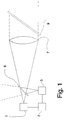
- an optical measurement system based on a beam splitter comprises a transmitter 1, from which an optical pulse is emitted via a beam splitter 5 to a lens 7, which launches the light pulse to a desired spatial angle.
- a window 9 is employed to prevent contamination of the optical element 7.
- the beam splitter 5 guides the returning light to a receiver 3.
- Adapted to the receiver 3 is also a unit 2 which is synchronized to the transmitter 1 and is capable of determining the delay and intensity of the return pulse, whereby such information can be utilized to define the object from which the reflection of the optical signal takes place.
- a Y-coupler 11 implemented by means of optical fibers takes place in the same manner as in the embodiment illustrated in Fig. 1.
- the beam splitter is replaced by a Y-coupler 11, which achieves a better directional gain for guiding the optical measurement signal to the desired object, since the losses by the upward reflection (cf. Fig. 1) caused by the beam splitter are avoided.
- the Y-coupler 11 has a drawback of optical signal stray coupling within the common part of the divider directly into the receiver input fibers during the transmission of the outgoing pulse. Hence, similar problems are involved as those discussed in conjunction with Fig. 1.
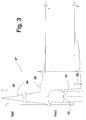
- the upper diagram of Fig. 3 shows the optical input of a receiver.
- the optical stray signal caused by the above-described reasons at the start of the measurement cycle loads the receiver input with a transient pulse signal 34 of approx. 1000-...1,000,000-fold intensity 35 compared with the normal signal level.
- said transient pulse signal 34 drives the receiver input amplifier into saturation during the period 33.
- the amplifier recovers from saturation, and though a backscatter input signal component 36 caused by mist is present, it cannot be detected from the amplifier output signal due to overload distortion 32.
- a reflection from a cloud or fixed object is present in the input signal. As is evident, also this later arriving signal can be corrupted by the overload distortion 32.
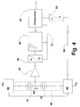
- amplifier overload can be avoided by configuring a conventional photoresponsive element 41 into a half-bridge with feedback element 42.
- the photoresponsive elements 41 and 42 are reverse-biased avalanche photodiodes.
- the stray signal coupled via optical stray coupling is canceled almost entirely.
- Bias adjustment of half-bridge permits fine-adjustment of the compensating effect of the feedback photodiode to a degree of substantially perfect cancellation of the transient signal resulting from optical stray coupling.
- Such arrangement achieves protection against overloading of the amplifier 43.
- the bias voltage can be continuously controlled by first converting the analog measurement signal into digital form with the help of an A/D converter 45 and then processing its digital output signal in an information processing unit 47.
- the A/D converter 45 used is typically a so-called FLASH converter operating with a sampling interval of 50 ns and resolution of 8 bits.
- the output signal of the A/D converter 45 is loaded in a FIFO (First-In/First-Out) register memory 48.
- the length of the intermediate register memory 48 can be. e.g., 512 samples.
- the microprocessor 47 is employed for controlling the sampling operation via a bus 54 which is connected to both the intermediate register memory 48 and the A/D converter 45.
- the fine-adjustment of the bias voltage is implemented through digitally steering from the information processing unit 47 a bias voltage generator 44 which controls the bias voltage over the photodiodes 41 and 42.
- the bias voltage control can be performed continuously without delay as the information processing unit senses the deviations in the stray signal cancellation accuracy of the measurement signal and can thus differentially either increase or decrease the bias voltage so as to achieve perfect stray signal cancellation.
- the bias voltage control is implemented by means of a constant-voltage regulator 40 connected to the positive supply voltage and an adjustable voltage regulator 44 which is connected to the negative supply voltage and receives its control voltage from the microprocessor 47 over the bus 56 via a D/A converter 58.
- the half-bridge 46 is advantageously complemented with a temperature-compensating circuit 49 which controls the voltage regulators 40 and 44.
- the half-bridge 46 formed by the diodes 41 and 42 can be considered a subtracting circuit which cancels the stray signal component from the measurement signal.
- the feedback of the optical signal in system based on a beam splitter 5 is implemented by means of an optical fiber 53 optically coupled to a feedback sensor element 51.
- the free end of the fiber 53 is placed to the opposite side of the beam splitter 5 relative to the receiver element 3.
- the length of the fiber 53 can be selected so that it produces a delay matching the delay of the most significant stray signal component. For instance, if the strongest stray signal component originates from the beam splitter, the delay caused by the fiber 53 must be adjusted to the delay on the optical path between the receiver 3 and the beam splitter.
- the delay caused by the fiber 53 must be adjusted to twice the delay on the optical path from the beam splitter 5 to the lens 7.
- the photoresponsive elements proper can be placed maximally tight to each other, whereby these elements can be kept in maximally identical ambient conditions.
- the free end of the fiber 53 can be made movable, thereby giving a further means of stray signal cancellation adjustment through moving the free end of the fiber 53, thus complementing the bias voltage control discussed above in conjunction with Fig. 4.
- the coarse adjustment is made mechanically bending the fiber end and then performing fine-adjustment by electronic means.
- the feedback signal can be taken via an optical power divider 61 when a Y-coupler is used.
- the power division ratio can be 2:2, for instance.
- the delay caused by the feedback fiber 65 between the optical power divider and the feedback signal sensor element 63 is adjusted essentially equal to the delay caused by the fiber 64 connecting the receiver 3 to the optical power divider 61.
- the invention is characterized in that the feedback sensor element is only used for measuring the stray signal component stemming from the optical stray coupling, particularly its waveform, which is scaled and equal phased prior to its subtraction from the uncorrected output signal of the receiver proper.
- the compensation of different delays can alternatively be arranged by means of digital delay circuits placed after the A/D converter, whereby both the measurement and the feedback signal can be delayed as necessary.
- the invention is particularly suited for use in conjunction with a Y-coupler implemented with optical fibers, while substantial benefits are also achieved in conjunction with measurement systems based on beam splitters illustrated in Figs. 1 and 5.
Landscapes
- Engineering & Computer Science (AREA)
- Physics & Mathematics (AREA)
- General Physics & Mathematics (AREA)
- Computer Networks & Wireless Communication (AREA)
- Radar, Positioning & Navigation (AREA)
- Remote Sensing (AREA)
- Chemical & Material Sciences (AREA)
- Life Sciences & Earth Sciences (AREA)
- Health & Medical Sciences (AREA)
- Analytical Chemistry (AREA)
- Biochemistry (AREA)
- General Health & Medical Sciences (AREA)
- Immunology (AREA)
- Pathology (AREA)
- Electromagnetism (AREA)
- Investigating Or Analysing Materials By Optical Means (AREA)
- Optical Radar Systems And Details Thereof (AREA)
- Photometry And Measurement Of Optical Pulse Characteristics (AREA)
- Measurement Of Optical Distance (AREA)
Applications Claiming Priority (2)
| Application Number | Priority Date | Filing Date | Title |
|---|---|---|---|
| FI923432 | 1992-07-30 | ||
| FI923432A FI94559C (fi) | 1992-07-30 | 1992-07-30 | Menetelmä ja laitteisto ilmakehän näkyvyyden ja valosironnan mittaamiseksi, jossa laitteistossa lähetykselle ja vastaanotolle käytetään yhteistä optiikkaa |
Publications (2)
| Publication Number | Publication Date |
|---|---|
| EP0583075A1 true EP0583075A1 (fr) | 1994-02-16 |
| EP0583075B1 EP0583075B1 (fr) | 1997-05-07 |
Family
ID=8535664
Family Applications (1)
| Application Number | Title | Priority Date | Filing Date |
|---|---|---|---|
| EP93305511A Expired - Lifetime EP0583075B1 (fr) | 1992-07-30 | 1993-07-14 | Procédé et appareil pour mesurer la visibilité météoroligique et la diffusion de la lumière |
Country Status (7)
| Country | Link |
|---|---|
| US (1) | US5504577A (fr) |
| EP (1) | EP0583075B1 (fr) |
| JP (1) | JPH06167447A (fr) |
| AT (1) | ATE152826T1 (fr) |
| AU (1) | AU663792B2 (fr) |
| DE (1) | DE69310456T2 (fr) |
| FI (1) | FI94559C (fr) |
Cited By (3)
| Publication number | Priority date | Publication date | Assignee | Title |
|---|---|---|---|---|
| EP0662619A3 (fr) * | 1994-01-11 | 1996-05-15 | Vaisala Oy | Appareil et méthode pour mesurer la limite de visibilité et le temps actuel. |
| US8190030B2 (en) | 2005-11-10 | 2012-05-29 | Optical Air Data Systems, Llc | Single aperture multiple optical waveguide transceiver |
| US10495787B2 (en) | 2016-06-16 | 2019-12-03 | I.M. Systems Group, Inc. | Integrated weather projection systems, methods, and apparatuses |
Families Citing this family (11)
| Publication number | Priority date | Publication date | Assignee | Title |
|---|---|---|---|---|
| US6108084A (en) * | 1995-08-17 | 2000-08-22 | Robert Bosch Gmbh | Combined sensor device for measuring both rain-covered area on and visual range through a windshield of a motor vehicle |
| US6034760A (en) * | 1997-10-21 | 2000-03-07 | Flight Safety Technologies, Inc. | Method of detecting weather conditions in the atmosphere |
| DE19912971C1 (de) * | 1999-03-23 | 2000-09-21 | Daimler Chrysler Ag | Verfahren zur Erfassung der Lichtleistung einer Sendediode einer optischen Überwachungseinheit sowie geeignete Schaltungsanordnung |
| AUPR813101A0 (en) * | 2001-10-08 | 2001-11-01 | Almos Systems Pty Ltd | Improvements in transmissometers |
| US7557734B2 (en) * | 2004-04-05 | 2009-07-07 | The United States Of America As Represented By The Secretary Of The Army | Airborne visibility indicator system and method |
| US10451518B2 (en) * | 2016-05-10 | 2019-10-22 | Rd2, Llc | All fiber temperature and air density sensor |
| US10921810B2 (en) | 2016-08-02 | 2021-02-16 | Pcms Holdings, Inc. | System and method for optimizing autonomous vehicle capabilities in route planning |
| WO2018106774A1 (fr) | 2016-12-08 | 2018-06-14 | Pcms Holdings, Inc. | Système et procédé de routage et de réorganisation d'un peloton de véhicules dans une ville intelligente |
| US10520592B2 (en) | 2016-12-31 | 2019-12-31 | Waymo Llc | Light detection and ranging (LIDAR) device with an off-axis receiver |
| RU2692822C1 (ru) * | 2018-07-09 | 2019-06-28 | Михаил Карпович Шайков | Способ определения метеорологической дальности видимости |
| WO2021108776A2 (fr) | 2019-11-27 | 2021-06-03 | University Of Utah Research Foundation | Mesure de particules pouvant s'évaporer à base d'émissivité différentielle |
Citations (2)
| Publication number | Priority date | Publication date | Assignee | Title |
|---|---|---|---|---|
| FR2594535A1 (fr) * | 1986-02-18 | 1987-08-21 | Renault | Dispositif de telemetrie optique |
| EP0358507A2 (fr) * | 1988-09-08 | 1990-03-14 | Vaisala Oy | Appareil pour mesurer la diffusion de la lumière |
Family Cites Families (6)
| Publication number | Priority date | Publication date | Assignee | Title |
|---|---|---|---|---|
| US3430047A (en) * | 1965-01-04 | 1969-02-25 | Sanders Associates Inc | Background cancelling optical detection system |
| US4397549A (en) * | 1981-03-27 | 1983-08-09 | The United States Of America As Represented By The Secretary Of The Army | Method for removal of LIDAR background backscattering by subtraction of multiple-delayed return signal |
| SE455541B (sv) * | 1983-04-18 | 1988-07-18 | Asea Ab | Forfarande for styrning av energien hos metsignaler fran en molnhojdsmetare samt molnhojdsmetare for genomforande av forfarandet |
| DE3536659A1 (de) * | 1984-12-27 | 1986-07-03 | Impulsphysik Gmbh, 2000 Hamburg | Vorrichtung zur wolkenhoehenmessung |
| DE3735267C3 (de) * | 1987-10-17 | 1996-03-21 | Telefunken Microelectron | Vorrichtung zur Sichtweitenmessung |
| FR2666153B1 (fr) * | 1990-08-23 | 1993-05-07 | Commissariat Energie Atomique | Procede et dispositif telemetriques. |
-
1992
- 1992-07-30 FI FI923432A patent/FI94559C/fi active
-
1993
- 1993-07-14 EP EP93305511A patent/EP0583075B1/fr not_active Expired - Lifetime
- 1993-07-14 AT AT93305511T patent/ATE152826T1/de not_active IP Right Cessation
- 1993-07-14 DE DE69310456T patent/DE69310456T2/de not_active Expired - Fee Related
- 1993-07-21 AU AU42112/93A patent/AU663792B2/en not_active Ceased
- 1993-07-29 JP JP5188505A patent/JPH06167447A/ja not_active Withdrawn
-
1995
- 1995-07-14 US US08/502,604 patent/US5504577A/en not_active Expired - Lifetime
Patent Citations (2)
| Publication number | Priority date | Publication date | Assignee | Title |
|---|---|---|---|---|
| FR2594535A1 (fr) * | 1986-02-18 | 1987-08-21 | Renault | Dispositif de telemetrie optique |
| EP0358507A2 (fr) * | 1988-09-08 | 1990-03-14 | Vaisala Oy | Appareil pour mesurer la diffusion de la lumière |
Cited By (6)
| Publication number | Priority date | Publication date | Assignee | Title |
|---|---|---|---|---|
| EP0662619A3 (fr) * | 1994-01-11 | 1996-05-15 | Vaisala Oy | Appareil et méthode pour mesurer la limite de visibilité et le temps actuel. |
| AU697118B2 (en) * | 1994-01-11 | 1998-09-24 | Vaisala Oy | Apparatus and method for measuring visibility and present weather |
| US8190030B2 (en) | 2005-11-10 | 2012-05-29 | Optical Air Data Systems, Llc | Single aperture multiple optical waveguide transceiver |
| US10495787B2 (en) | 2016-06-16 | 2019-12-03 | I.M. Systems Group, Inc. | Integrated weather projection systems, methods, and apparatuses |
| US11048022B2 (en) | 2016-06-16 | 2021-06-29 | I.M. Systems Group, Inc. | Integrated weather projection systems, methods, and apparatuses |
| US11841480B2 (en) | 2016-06-16 | 2023-12-12 | I.M. Systems Group, Inc. | Integrated weather projection systems, methods, and apparatuses |
Also Published As
| Publication number | Publication date |
|---|---|
| AU663792B2 (en) | 1995-10-19 |
| FI94559C (fi) | 1995-09-25 |
| FI923432L (fi) | 1994-01-31 |
| ATE152826T1 (de) | 1997-05-15 |
| DE69310456D1 (de) | 1997-06-12 |
| FI923432A0 (fi) | 1992-07-30 |
| AU4211293A (en) | 1994-02-03 |
| EP0583075B1 (fr) | 1997-05-07 |
| US5504577A (en) | 1996-04-02 |
| FI94559B (fi) | 1995-06-15 |
| DE69310456T2 (de) | 1997-12-18 |
| JPH06167447A (ja) | 1994-06-14 |
Similar Documents
| Publication | Publication Date | Title |
|---|---|---|
| EP0583075B1 (fr) | Procédé et appareil pour mesurer la visibilité météoroligique et la diffusion de la lumière | |
| US4699508A (en) | Method of measuring the distance of a target and apparatus for its performance | |
| EP0662619B1 (fr) | Appareil et méthode pour mesurer la limite de visibilité et le temps actuel | |
| JP7650967B2 (ja) | Lidarシステムにおける位相障害を補償する技術 | |
| US5002388A (en) | Optical distance measuring apparatus having a measurement error compensating function | |
| EP0168182A2 (fr) | Appareil de mesure optique | |
| JPS6223264B2 (fr) | ||
| JPH07128438A (ja) | レーダー測距装置の距離補正方法 | |
| EP4318025B1 (fr) | Dispositif de mesure à balayage avec réseau de fibres | |
| JP7645368B2 (ja) | 光検出及およ測距(lidar)システムにおける位相障害を補償する方法 | |
| JPH10339667A (ja) | 光測定器 | |
| JP3225352B2 (ja) | 電波距離計 | |
| JPH07248374A (ja) | 距離測定装置 | |
| JP2001124854A (ja) | レーザ測距装置およびその較正機構 | |
| JPS61145476A (ja) | 光学的距離測定装置 | |
| JP3022987U (ja) | 光電測距儀用の電子制御装置 | |
| GB2211605A (en) | Optical fibre distributor sensor | |
| SU918822A1 (ru) | Устройство дл определени оптических характеристик атмосферы | |
| JPH11160419A (ja) | レーザレーダのアライメント調整装置 | |
| JPS61272677A (ja) | 光路長測定器 | |
| JP2002341030A (ja) | 距離測定装置および距離測定方法 | |
| JPH0792268A (ja) | レーザ・レンジ・ファインダのデータ処理装置 | |
| JPH0429024A (ja) | 温度計測システム | |
| GB2149256A (en) | Phase measurement | |
| JPH04351932A (ja) | 光ファイバ式温度分布測定装置 |
Legal Events
| Date | Code | Title | Description |
|---|---|---|---|
| PUAI | Public reference made under article 153(3) epc to a published international application that has entered the european phase |
Free format text: ORIGINAL CODE: 0009012 |
|
| AK | Designated contracting states |
Kind code of ref document: A1 Designated state(s): AT BE CH DE DK ES FR GB GR IE IT LI LU MC NL PT SE |
|
| 17P | Request for examination filed |
Effective date: 19940621 |
|
| GRAG | Despatch of communication of intention to grant |
Free format text: ORIGINAL CODE: EPIDOS AGRA |
|
| 17Q | First examination report despatched |
Effective date: 19960820 |
|
| GRAH | Despatch of communication of intention to grant a patent |
Free format text: ORIGINAL CODE: EPIDOS IGRA |
|
| GRAH | Despatch of communication of intention to grant a patent |
Free format text: ORIGINAL CODE: EPIDOS IGRA |
|
| GRAA | (expected) grant |
Free format text: ORIGINAL CODE: 0009210 |
|
| AK | Designated contracting states |
Kind code of ref document: B1 Designated state(s): AT BE CH DE DK ES FR GB GR IE IT LI LU MC NL PT SE |
|
| PG25 | Lapsed in a contracting state [announced via postgrant information from national office to epo] |
Ref country code: NL Free format text: LAPSE BECAUSE OF FAILURE TO SUBMIT A TRANSLATION OF THE DESCRIPTION OR TO PAY THE FEE WITHIN THE PRESCRIBED TIME-LIMIT Effective date: 19970507 Ref country code: LI Effective date: 19970507 Ref country code: IT Free format text: LAPSE BECAUSE OF FAILURE TO SUBMIT A TRANSLATION OF THE DESCRIPTION OR TO PAY THE FEE WITHIN THE PRESCRIBED TIME-LIMIT;WARNING: LAPSES OF ITALIAN PATENTS WITH EFFECTIVE DATE BEFORE 2007 MAY HAVE OCCURRED AT ANY TIME BEFORE 2007. THE CORRECT EFFECTIVE DATE MAY BE DIFFERENT FROM THE ONE RECORDED. Effective date: 19970507 Ref country code: GR Free format text: LAPSE BECAUSE OF FAILURE TO SUBMIT A TRANSLATION OF THE DESCRIPTION OR TO PAY THE FEE WITHIN THE PRESCRIBED TIME-LIMIT Effective date: 19970507 Ref country code: ES Free format text: THE PATENT HAS BEEN ANNULLED BY A DECISION OF A NATIONAL AUTHORITY Effective date: 19970507 Ref country code: DK Effective date: 19970507 Ref country code: CH Effective date: 19970507 Ref country code: BE Effective date: 19970507 Ref country code: AT Effective date: 19970507 |
|
| REF | Corresponds to: |
Ref document number: 152826 Country of ref document: AT Date of ref document: 19970515 Kind code of ref document: T |
|
| REG | Reference to a national code |
Ref country code: CH Ref legal event code: EP |
|
| REF | Corresponds to: |
Ref document number: 69310456 Country of ref document: DE Date of ref document: 19970612 |
|
| PG25 | Lapsed in a contracting state [announced via postgrant information from national office to epo] |
Ref country code: LU Free format text: LAPSE BECAUSE OF NON-PAYMENT OF DUE FEES Effective date: 19970714 Ref country code: IE Free format text: LAPSE BECAUSE OF NON-PAYMENT OF DUE FEES Effective date: 19970714 |
|
| REG | Reference to a national code |
Ref country code: IE Ref legal event code: FG4D Free format text: 73775 |
|
| PG25 | Lapsed in a contracting state [announced via postgrant information from national office to epo] |
Ref country code: PT Effective date: 19970807 Ref country code: GB Free format text: LAPSE BECAUSE OF NON-PAYMENT OF DUE FEES Effective date: 19970807 |
|
| ET | Fr: translation filed | ||
| NLV1 | Nl: lapsed or annulled due to failure to fulfill the requirements of art. 29p and 29m of the patents act | ||
| REG | Reference to a national code |
Ref country code: CH Ref legal event code: PL |
|
| PG25 | Lapsed in a contracting state [announced via postgrant information from national office to epo] |
Ref country code: MC Free format text: LAPSE BECAUSE OF NON-PAYMENT OF DUE FEES Effective date: 19980131 |
|
| PLBE | No opposition filed within time limit |
Free format text: ORIGINAL CODE: 0009261 |
|
| STAA | Information on the status of an ep patent application or granted ep patent |
Free format text: STATUS: NO OPPOSITION FILED WITHIN TIME LIMIT |
|
| GBPC | Gb: european patent ceased through non-payment of renewal fee |
Effective date: 19970807 |
|
| 26N | No opposition filed | ||
| PGFP | Annual fee paid to national office [announced via postgrant information from national office to epo] |
Ref country code: FR Payment date: 20090716 Year of fee payment: 17 |
|
| PGFP | Annual fee paid to national office [announced via postgrant information from national office to epo] |
Ref country code: SE Payment date: 20090715 Year of fee payment: 17 Ref country code: DE Payment date: 20090722 Year of fee payment: 17 |
|
| REG | Reference to a national code |
Ref country code: FR Ref legal event code: ST Effective date: 20110331 |
|
| PG25 | Lapsed in a contracting state [announced via postgrant information from national office to epo] |
Ref country code: DE Free format text: LAPSE BECAUSE OF NON-PAYMENT OF DUE FEES Effective date: 20110201 |
|
| REG | Reference to a national code |
Ref country code: DE Ref legal event code: R119 Ref document number: 69310456 Country of ref document: DE Effective date: 20110201 |
|
| PG25 | Lapsed in a contracting state [announced via postgrant information from national office to epo] |
Ref country code: FR Free format text: LAPSE BECAUSE OF NON-PAYMENT OF DUE FEES Effective date: 20100802 |
|
| PG25 | Lapsed in a contracting state [announced via postgrant information from national office to epo] |
Ref country code: SE Free format text: LAPSE BECAUSE OF NON-PAYMENT OF DUE FEES Effective date: 20100715 |