EP0583403B1 - Former - Google Patents
Former Download PDFInfo
- Publication number
- EP0583403B1 EP0583403B1 EP92912978A EP92912978A EP0583403B1 EP 0583403 B1 EP0583403 B1 EP 0583403B1 EP 92912978 A EP92912978 A EP 92912978A EP 92912978 A EP92912978 A EP 92912978A EP 0583403 B1 EP0583403 B1 EP 0583403B1
- Authority
- EP
- European Patent Office
- Prior art keywords
- stock
- shoe
- wire
- water
- wires
- Prior art date
- Legal status (The legal status is an assumption and is not a legal conclusion. Google has not performed a legal analysis and makes no representation as to the accuracy of the status listed.)
- Expired - Lifetime
Links
- XLYOFNOQVPJJNP-UHFFFAOYSA-N water Substances O XLYOFNOQVPJJNP-UHFFFAOYSA-N 0.000 claims abstract description 46
- 238000011144 upstream manufacturing Methods 0.000 claims abstract description 28
- 230000014759 maintenance of location Effects 0.000 claims abstract description 4
- 229910010293 ceramic material Inorganic materials 0.000 claims description 2
- 230000002708 enhancing effect Effects 0.000 claims description 2
- 230000000750 progressive effect Effects 0.000 claims description 2
- 238000003490 calendering Methods 0.000 claims 1
- 238000000034 method Methods 0.000 description 2
- 238000012986 modification Methods 0.000 description 2
- 230000004048 modification Effects 0.000 description 2
- 230000015572 biosynthetic process Effects 0.000 description 1
- 239000004927 clay Substances 0.000 description 1
- 239000011248 coating agent Substances 0.000 description 1
- 238000000576 coating method Methods 0.000 description 1
- 239000000945 filler Substances 0.000 description 1
- 238000004519 manufacturing process Methods 0.000 description 1
- 239000007787 solid Substances 0.000 description 1
Images

Classifications
-
- D—TEXTILES; PAPER
- D21—PAPER-MAKING; PRODUCTION OF CELLULOSE
- D21F—PAPER-MAKING MACHINES; METHODS OF PRODUCING PAPER THEREON
- D21F9/00—Complete machines for making continuous webs of paper
- D21F9/003—Complete machines for making continuous webs of paper of the twin-wire type
Definitions
- the present invention relates to a forming apparatus and a method for forming a web from stock having an ash content above 20 percent. More particularly, the present invention relates to a forming apparatus using a high ash content stock in which the resultant web is supercalendered in order to provide a printable surface thereon.
- Two-sidedness in the present specification means that the surface characteristics of one surface of the resultant web is substantially different from the surface characteristics of the opposite surface of the web. Such two-sidedness causes problems when both sides of the resultant web are to be printed thereon.
- Machine speeds in the region of 1,600 meters per minute, which is equivalent to 5,200 feet per minute, are envisaged, and at such speed requires even removal or balanced removal of water within the stock from both surfaces thereof is essential.
- the present invention provides a vertical former which includes a pair of wires which cooperate together to define therebetween a vertical forming section.
- a headbox is disposed closely adjacent to the lower or upstream end of the forming section so that the stock is ejected from the headbox upwardly into the forming section.
- a curved shoe means is disposed immediately downstream relative to the upstream end of the forming section.
- Such curved shoe means has a very large radius of curvature within the range of 6,35 to 8,89 m (250 to 350 inches) and preferably 7,62 m (300 inches).
- the arrangement is such that water is removed centrifugally away from the curved shoe means through a first wire, while a further portion of water is removed through the curved shoe means through the second wire.
- a dewatering means is disposed downstream relative to the curved shoe means with the dewatering means having a radius of curvature which is opposite to the radius of curvature of the curved shoe means.
- the dewatering means is structured such that the amount of water removed through the first wire by the dewatering means and by the curved shoe means is approximately equal to the volume of water removed through the second wire through the curved shoe means and through the second wire as the stock and wires move past the dewatering means.
- the amount of water removed from the stock is evenly balanced as the stock is formed into a web so that the ash content or clay or filler within the stock is evenly distributed throughout the formed web.
- the forming section includes dewatering means 56,58 and 60 arranged in staggered relationship along the forming section for dewatering the web.
- the present invention provides a curved shoe means which may have three blades approximately 15 cm (six inches) wide in a machine direction with a spacing of approximately 5 cm (two inches) between each blade.
- Such spacing of the three blades or shoes combined with the very large radius of curvature of the curved shoe means, gives low intensity forming pulses to the stock so that the stock is gently dewatered during the initial or upstream portion of the forming section.
- Another object of the present invention is the provision of a web from a high ash content stock such that during subsequent supercalendering of the resultant web, even or similar surface characteristics of the web on both sides thereof are attained.
- the present invention relates to a forming apparatus and method for forming a web from stock having an ash content above 20 percent.
- the forming apparatus includes a headbox for projecting a stream of the stock and a first and second endless looped forming wire which cooperate together to define therebetween a forming section having an upstream and a downstream end.
- the upstream end of the forming section is disposed closely adjacent to the headbox such that the stream of stock is directed into the upstream end of the forming section.
- the curved shoe means is disposed immediately downstream relative to the upstream end of the forming section.
- the second wire is disposed between the first wire and the curved shoe means. The arrangement is such that a first portion of water is removed through the first wire when the wires and the stock move over the curved shoe means.
- a dewatering means is disposed between the curved shoe means and the downstream end of the forming section.
- the dewatering means cooperates with the first wire and is disposed on the opposite side of the wires relative to the curved shoe means.
- the dewatering means has a radius of curvature which is less than the curvature than that of the curved shoe means.
- the curvature of the dewatering means is in an opposite sense to the curvature of the curved shoe means. The arrangement is such that a second portion of water is removed from the stock through the second wire during movement of the stock and the wires over the dewatering means.
- a further dewatering shoe is disposed between the dewatering means and the downstream end of the forming section.
- the further shoe cooperates with the second wire and is disposed on the same side of the wires as the shoe means.
- the further shoe is connected to a source of partial vacuum such that a third portion of water is removed from the stock through the second wire during movement of the stock and the wires over the further shoe.
- the arrangement is such that from the upstream to the downstream end of the forming section, water is progressively removed from the stock through both wires so that two-sidedness of the resultant web is minimized while maintaining maximum retention of the ash within the web.
- Figure 1 is a side-elevational view of a forming apparatus, generally designated 10, according to the present invention for forming a web W from stock S having an ash content of at least 20 percent.
- the apparatus 10 includes a headbox 12 for ejecting a stream 14 of the stock S .
- the upstream end 22 is disposed closely adjacent to the headbox 12 such that the stream 14 of stock S is directed into the upstream end 22 of the forming section.
- Curved shoe means is disposed immediately downstream relative to the upstream end 22 of the forming section 20.
- the second wire 18 is disposed between the first wire 16 and the curved shoe means 26.
- the arrangement is such that a first portion of water is removed through the first wire 16 when the wires 16 and 18 and the stock S move over the shoe means 26 .
- a dewatering means is disposed between the shoe means 26 and the downstream end 24 of the forming section 20 .
- the dewatering means 30 cooperates with the first wire 16 and is disposed on the opposite side of the wires 16 and 18 relative to the curved shoe means 26.
- the dewatering means 30 has a radius of curvature which is less than the radius of curvature of the curved shoe 26. Also, the curvature of the dewatering means 30 is in an opposite sense to the curvature of the curved shoe means 26 .
- the arrangement is such that a second portion of water, as indicated by the arrow 32 , is removed from the stock S through the second wire during movement of the stock S over the dewatering means 30.
- a further dewatering shoe is disposed between the dewatering means 30 and the downstream end 24 of the forming section 20 .
- the further shoe 34 cooperates with the second wire 18 and is disposed on the same side of the wires 16 and 18 as the curved shoe means 26 .
- the further shoe 34 is connected to a source of partial vacuum 36 such that a third portion of water, as indicated by the arrow 38 , is removed from the stock S through the second wire 18 during movement of the stock S and wires 16 and 18 over the further shoe 34 .
- the arrangement is such that from the upstream to the downstream end 22 and 24 , respectively, of the forming section 20, water is progressively removed from the stock S through both wires 16 and 18 so that two-sidedness of the resultant web is minimized while maintaining maximum retention of the ash within the web.
- the headbox 12 includes a plurality of trailing elements 40, 41 and 42 for controlling the turbulence of stock S within the headbox 12 .
- the forming apparatus 10 also includes a first and second turning bar 44 and 46, respectively, disposed within the first and second looped wires 16 and 18, respectively, for guiding the wires 16 and 18 into close proximity relative to the headbox 12 .
- the arrangement is such that the distance between the headbox 12 and upstream end 22 of the forming section 20 is minimized.
- the curved shoe means 26 has a radius of curvature within the range of 6,35 to 8,89 m (250 to 350 inches) and, in a preferred embodiment of the present invention, the radius of curvature of the curved shoe means 26 is 7,62 m (300 inches).
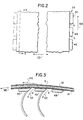
- the curved shoe means 26 may be in the form of a solid shoe but preferably, and as shown in Figure 1, the curved shoe means 26 includes a plurality of shoes 48, 49 and 50.
- Figure 2 is an enlarged plan view of the curved shoe means 26 and shows the plurality of shoes 48 to 50.
- Each shoe of said plurality of shoes 48 to 50 extends in a cross-machine direction, as indicated by the arrow CD , with each shoe of the plurality of shoes 48 to 50 defining a gap G between adjacent shoes in a machine direction, as indicated by the arrow MD.
- the plurality of shoes 48 to 50 are of ceramic material.
- Figure 3 is a sectional view taken on the line 3-3 of Figure 2 and shows a further portion of water, as indicated by the arrow 52, being removed from the stock S to the second wire 18. The further portion of water 52 is removed between each gap G defined between the adjacent shoes.
- the further portion of water 52 and the second portion of water 32 are substantially equal in volume to the first portion of water 28 and a fourth portion of water, as indicated by the arrow 54 , shown in Figure 1 through the first wire 16 during movement of the stock S and the wires 16 and 18 over the dewatering means 30 .
- the arrangement is such that ash within the stock S is evenly distributed on both sides of the web W so that during subsequent supercalendering of the web W , the resultant web exhibits enhanced printing characteristics on both sides thereof.
- the dewatering means 30 is connected to a source of partial vacuum, generally designated 56 , as shown in Figure 1.
- the source of partial vacuum 56 assists removal of the fourth portion of water 54 from the stock S .
- the dewatering means 30 further includes an upstream and a downstream portion 58 and 60, respectively.
- the upstream portion 58 is connected to a lower source of partial vacuum 62 than the downstream portion 60 for enhancing the progressive removal of the fourth portion of water 54 from the stock S moving through the forming section 20 .
- the further dewatering shoe 34 is a curved shoe.
- the further shoe 34 has a radius of curvature which is in the same sense of direction as the radius of curvature of the curved shoe means 26.
- the arrangement is such that a fifth portion of water, indicated by the arrow 64 , is removed through the first wire 16 during movement of the stock S and the wires 16 and 18 over the further shoe 34 .
- a high ash content stock S is ejected from the headbox 12 vertically into the upstream end 22 of the forming section 20 .
- a first portion of water 28 is removed from the stock through the first wire 16 during movement of the stock and the wires over the curved shoe 26 .
- a second portion of water is removed from the stock through the second wire 18 during movement of the stock and the wires over the dewatering device 30 .
- a third portion of water is removed from the stock from the second wire 18 during movement of the stock and the wires over the further dewatering shoe 34 .
- the further dewatering shoe 34 is disposed within the first looped forming wire and has a radius of curvature in the same direction as the curvature of the curved shoe means. Such curvature is opposite the curvature of the dewatering shoe so that as the stock progresses from the upstream to the downstream end of the forming section, water is evenly and progressively removed from both sides of the web so that during a subsequent supercalendering of the web, the subsequent supercalendered web exhibits certain characteristics, including smoothness and gloss, which enable printing on both sides thereof.
- the present invention provides a forming apparatus which enables the production of a supercalendered web from high ash content stock at extremely high speeds without the need for any coating being applied thereon.
Landscapes
- Paper (AREA)
Claims (6)
- Blattbildungsvorrichtung (10) zum Herstellen einer Bahn (W) aus Stoff (S), wobei die Vorrichtung aufweist:einen Stoffauflaufkasten (12) zum vertikalen Ausstoßen eines Stroms des Stoffes (S);ein erstes und ein zweites zu einer endlosen Schleife geformtes Blattbildungssieb (16, 18), die gemeinsam zwischen sich einen vertikalen Blattbildungsabschnitt (20) bilden, der ein stromaufwärtiges und ein stromabwärtiges Ende (22, 24) hat, wobei das stromaufwärtige Ende (22) eng benachbart zu dem Stoffauflaufkasten (12) angeordnet ist, so daß der Strom des Stoffes (S) vertikal aufwärts in das stromaufwärtige Ende (22) des Blattbildungsabschnitts (20) gerichtet wird;eine gekrümmte Schuheinrichtung (26), die mit dem zweiten Sieb (18) zusammenwirkt, wobei die Schuheinrichtung (26) relativ zu dem stromaufwärtigen Ende (22) des Blattbildungsabschnitts (20) unmittelbar stromabwärts angeordnet ist, wobei das zweite Sieb (18) zwischen dem ersten Sieb (16) und der Schuheinrichtung (26) angeordnet ist und wobei die Anordnung so getroffen ist, daß ein erster Teil Wasser (28) durch das erste Sieb (16) entfernt wird, wenn sich die Siebe (16, 18) und der Stoff (S) über die Schuheinrichtung (26) bewegen;wobei die gekrümmte Schuheinrichtung (26) aufweist:mehrere Schuhe (48-50), wobei sich jeder Schuh von den mehreren Schuhen (48-50) in Maschinenquerrichtung (CD) erstreckt, wobei jeder Schuh der mehreren Schuhe (48-50) einen Spalt (G) mit einem benachbarten Schuh in Maschinenrichtung (MD) bildet und wobei die Anordnung so getroffen ist, daß ein weiterer Teil Wasser (52) aus dem Stoff durch das zweite Sieb (18) entfernt wird, wobei der weitere Teil Wasser (52) in dem Spalt (G) entfernt wird, der zwischen den benachbarten Schuhen (48-50) gebildet ist;eine stationäre Entwässerungseinrichtung (30), die zwischen der Schuheinrichtung (26) und dem stromabwärtigen Ende (24) des Blattbildungsabschnitts (20) angeordnet ist; wobei die Entwässerungseinrichtung (30) mit dem ersten Sieb (16) zusammenwirkt und auf der entgegengesetzten Seite der Siebe (16, 18) relativ zu der Schuheinrichtung (26) angeordnet ist, wobei die Entwässerungseinrichtung (30) einen Krümmungsradius hat, der kleiner als der der gekrümmten Schuheinrichtung (26) ist, wobei die Entwässerungseinrichtung (30) eine Krümmung in einem Sinn hat, der zu dem der Krümmung der gekrümmten Schuheinrichtung (26) entgegengesetzt ist, und wobei die Anordnung so getroffen ist, daß ein zweiter Teil Wasser (32) aus dem Stoff (S) durch das zweite Sieb (18) während der Bewegung des Stoffes und der Siebe (16, 18) über die Entwässerungseinrichcung (30) entfernt wird; undeinen weiteren Entwässerungsschuh (34), der zwischen der Entwässerungseinrichtung (30) und dem stromabwärtigen Ende (24) des Blattbildungsabschnitts (20) angeordnet ist, wobei der weitere Schuh (34) mit dem zweiten Sieb (18) zusammenwirkt und auf derselben Seite der Siebe (16, 18) wie die schuheinrichtung (26) angeordnet ist, wobei der weitere Schuh (34) mit einer Teilvakuumquelle (36) verbunden ist, so daß ein dritter Teil Wasser (38) aus dem Stoff (S) durch das zweite Sieb (18) während der Bewegung des Stoffes (S) und der Siebe (16, 18) über den weiteren Schuh (34) entfernt wird, und wobei die Anordnung so getroffen ist, daß von dem stromaufwärtigen Ende (22) zu dem stromabwärtigen Ende (24) des Blattbildungsabschnitts (20)der weitere Entwässerungsschuh (34) ein gekrümmter Schuh ist; undder weitere Schuh (34) einen Krümmungsradius in demselben Sinne wie der Krümmungsradius der gekrümmten Schuheinrichtung (26) hat, so daß ein fünfter Teil Wasser (64) durch das erste Sieb (16) während der Bewegung des Stoffes (S) und der Siebe (16, 18) über den weiteren Schuh (34) entfernt wird;dadurch gekennzeichnet, daß die Blattbildungsvorrichtung weiter aufweist:eine erste und eine zweite Umlenkschiene (44, 46), die innerhalb des ersten bzw. des zweiten zur Schleife geformten Siebes (16, 18) angeordnet sind, um die Siebe (16, 18) in enge Nähe relativ zu dem Stoffauflaufkasten (12) zu führen, so daß die Distanz zwischen dem Stoffauflaufkasten (12) und dem stromaufwärtigen Ende (22) des Blattbildungsabschnitts (20) minimiert wird; undwobei der weitere Teil Wasser (52) und der zweite Teil Wasser (32) im wesentlichen das gleiche Volumen wie der erste Teil Wasser (28) haben und ein vierter Teil Wasser (54) durch das erste Sieb (16) während der Bewegung des Stoffes und der Siebe über die Entwässerungseinrichtung (30) entfernt wird, wodurch Wasser zunehmend und gleichmäßig aus dem Stoff (S) durch beide Siebe (16, 18) entfernt wird, so daß eine Zweiseitigkeit der resultierenden Bahn minimiert wird, während ein maximales Zurückhalten der Asche in der Bahn aufrechterhalten wird, wobei die Anordnung so getroffen ist, daß Asche in dem Stoff (S), der einen Aschegehalt von über 20 Prozent hat, auf beide Seiten der Bahn (W) gleichmäßig verteilt wird, so daß während eines anschließenden Hochglanzkalanderns der Bahn die resultierende Bahn verbesserte Bedruckungseigenschaften auf ihren beiden Seiten aufweist.
- Blattbildungsvorrichtung nach Anspruch 1, dadurch gekennzeichnet, daß der Stoffauflaufkasten (12) weiter aufweist: mehrere Schleppelemente (40-42) zum Steuern der Turbulenz des Stoffes (S) innerhalb des Stoffauflaufkastens (12).
- Blattbildungsvorrichtung nach Anspruch 1, dadurch gekennzeichnet, daß die gekrümmte Schuheinrichtung (26) einen Krümmungsradius in einem Bereich von 6,35 - 8,89 m (250-350 Zoll) hat.
- Blattbildungsvorrichtung nach Anspruch 1, dadurch gekennzeichnet, daß die Schuhe (48-50) aus Keramikmaterial bestehen.
- Blattbildungsvorrichtung nach Anspruch 1, dadurch gekennzeichnet, daß die Entwässerungseinrichtung (30) mit einer Teilvakuumquelle (56) zum Unterstützen des Entfernens des vierten Teils Wasser (54) aus dem Stoff verbunden ist.
- Blattbildungsvorrichtung nach Anspruch 5, dadurch gekennzeichnet, daß die Entwässerungseinrichtung (30) einen stromaufwärtigen und einen stromabwärtigen Teil (58, 60) aufweist, wobei der stromaufwärtige Teil (58) mit einer Quelle niedrigeren Teilvakuums (62) als der stromabwärtige Teil (60) verbunden ist, um das fortschreitende Entfernen des vierten Teils Wasser (54) aus dem Stoff, der sich durch den Blattbildungsabschnitt (20) bewegt, zu verbessern.
Applications Claiming Priority (3)
| Application Number | Priority Date | Filing Date | Title |
|---|---|---|---|
| US07/713,186 US5201999A (en) | 1991-06-10 | 1991-06-10 | Twin wire forming apparatus |
| US713186 | 1991-06-10 | ||
| PCT/US1992/003084 WO1992022704A1 (en) | 1991-06-10 | 1992-04-15 | A forming apparatus |
Publications (2)
| Publication Number | Publication Date |
|---|---|
| EP0583403A1 EP0583403A1 (de) | 1994-02-23 |
| EP0583403B1 true EP0583403B1 (de) | 1997-08-13 |
Family
ID=24865137
Family Applications (1)
| Application Number | Title | Priority Date | Filing Date |
|---|---|---|---|
| EP92912978A Expired - Lifetime EP0583403B1 (de) | 1991-06-10 | 1992-04-15 | Former |
Country Status (9)
| Country | Link |
|---|---|
| US (1) | US5201999A (de) |
| EP (1) | EP0583403B1 (de) |
| JP (1) | JP2604681B2 (de) |
| KR (1) | KR0179045B1 (de) |
| BR (1) | BR9206114A (de) |
| CA (1) | CA2110494C (de) |
| DE (2) | DE69221613T2 (de) |
| FI (1) | FI112097B (de) |
| WO (1) | WO1992022704A1 (de) |
Families Citing this family (7)
| Publication number | Priority date | Publication date | Assignee | Title |
|---|---|---|---|---|
| JP3244911B2 (ja) * | 1994-01-28 | 2002-01-07 | 三菱重工業株式会社 | 抄紙機のツインワイヤフォーマ |
| DE19652485A1 (de) * | 1996-12-17 | 1998-06-18 | Voith Sulzer Papiermasch Gmbh | Siebpartie und Verfahren zum Entwässern einer Faserstoffbahn in einer Siebpartie |
| FI104100B1 (fi) | 1998-06-10 | 1999-11-15 | Valmet Corp | Integroitu paperikone |
| US6372091B2 (en) | 1999-06-18 | 2002-04-16 | Metso Paper, Inc. | Method and apparatus for forming a paper web |
| DE10161056A1 (de) * | 2001-12-12 | 2003-06-26 | Voith Paper Patent Gmbh | Siebpartie |
| WO2005068714A1 (en) * | 2003-12-22 | 2005-07-28 | Astenjohnson, Inc | Gap type forming section for a two fabric paper making machine |
| DE102004000054A1 (de) * | 2004-11-23 | 2006-05-24 | Voith Paper Patent Gmbh | Blattbildungssystem einer Maschine zur Herstellung einer Faserstoffbahn |
Citations (1)
| Publication number | Priority date | Publication date | Assignee | Title |
|---|---|---|---|---|
| US3944464A (en) * | 1974-05-10 | 1976-03-16 | International Paper Company | Forming section for twin-wire papermaking machine |
Family Cites Families (11)
| Publication number | Priority date | Publication date | Assignee | Title |
|---|---|---|---|---|
| AT328283B (de) * | 1970-11-16 | 1976-03-10 | Arledter Hanns F Dr Ing | Verfahren und einrichtung zur herstellung vonfaserstoffbahnen mit raumlich ausgerichteten fasern |
| US4414061A (en) * | 1975-02-20 | 1983-11-08 | Australian Paper Manufacturers Limited | Twin wire paper forming apparatus |
| US4153504A (en) * | 1977-01-31 | 1979-05-08 | Beloit Corporation | Twin-wire fibrous web former and method |
| US4125428A (en) * | 1977-06-27 | 1978-11-14 | The Black Clawson Company | Vertical twin wire paper machine |
| FI70615C (fi) * | 1982-08-23 | 1986-09-24 | Ahlstroem Oy | Anordning foer att paoverka en pao en vira avvattnad fiberbana |
| FI840246A7 (fi) * | 1984-01-20 | 1985-07-21 | Valmet Oy | Foerfarande och anordning vid formning av pappersbana. |
| US4790909A (en) * | 1986-12-17 | 1988-12-13 | Beloit Corporation | Two-wire paper forming apparatus |
| GB8710428D0 (en) * | 1987-05-01 | 1987-06-03 | Beloit Corp | Multi-ply web forming apparatus |
| GB8903517D0 (en) * | 1989-02-16 | 1989-04-05 | Beloit Corp | A forming apparatus for forming a web from stock |
| DE3927597A1 (de) * | 1989-08-22 | 1991-02-28 | Voith Gmbh J M | Doppelsieb-former |
| US5034098A (en) * | 1990-02-23 | 1991-07-23 | Beloit Corporation | Method of forming a paper web |
-
1991
- 1991-06-10 US US07/713,186 patent/US5201999A/en not_active Expired - Lifetime
-
1992
- 1992-04-15 EP EP92912978A patent/EP0583403B1/de not_active Expired - Lifetime
- 1992-04-15 JP JP5500849A patent/JP2604681B2/ja not_active Expired - Lifetime
- 1992-04-15 DE DE69221613T patent/DE69221613T2/de not_active Expired - Fee Related
- 1992-04-15 WO PCT/US1992/003084 patent/WO1992022704A1/en not_active Ceased
- 1992-04-15 BR BR9206114A patent/BR9206114A/pt not_active IP Right Cessation
- 1992-04-15 KR KR1019930703682A patent/KR0179045B1/ko not_active Expired - Fee Related
- 1992-04-15 CA CA002110494A patent/CA2110494C/en not_active Expired - Fee Related
- 1992-04-15 DE DE0583403T patent/DE583403T1/de active Pending
-
1993
- 1993-12-09 FI FI935533A patent/FI112097B/fi active
Patent Citations (1)
| Publication number | Priority date | Publication date | Assignee | Title |
|---|---|---|---|---|
| US3944464A (en) * | 1974-05-10 | 1976-03-16 | International Paper Company | Forming section for twin-wire papermaking machine |
Non-Patent Citations (4)
| Title |
|---|
| US-A- 3 944 464 * |
| WO-A-90/09481 * |
| WO-A-91/02842 * |
| WO-A-91/13206 * |
Also Published As
| Publication number | Publication date |
|---|---|
| DE583403T1 (de) | 1994-09-22 |
| JPH07501361A (ja) | 1995-02-09 |
| KR0179045B1 (ko) | 1999-05-15 |
| CA2110494C (en) | 1996-06-11 |
| JP2604681B2 (ja) | 1997-04-30 |
| DE69221613D1 (en) | 1997-09-18 |
| EP0583403A1 (de) | 1994-02-23 |
| BR9206114A (pt) | 1995-10-10 |
| FI112097B (fi) | 2003-10-31 |
| FI935533A7 (fi) | 1993-12-09 |
| DE69221613T2 (de) | 1998-06-25 |
| FI935533A0 (fi) | 1993-12-09 |
| WO1992022704A1 (en) | 1992-12-23 |
| US5201999A (en) | 1993-04-13 |
Similar Documents
| Publication | Publication Date | Title |
|---|---|---|
| CA2489659C (en) | Forming of a paper or board web in a twin-wire former or in a twin-wire section of a former | |
| EP0359696B1 (de) | Verfahren und Vorrichtung zur Herstellung einer Papierbahn | |
| CA1242914A (en) | Process and equipment in the forming of paper web | |
| US4838996A (en) | Hydrofoil blade for producing turbulence | |
| US6372091B2 (en) | Method and apparatus for forming a paper web | |
| US5468348A (en) | Multi-ply web former and method | |
| US5201999A (en) | Twin wire forming apparatus | |
| EP0251985B1 (de) | Bahnformierungsanlage | |
| GB1602214A (en) | Vertical twin wire paper machine | |
| EP0335821A2 (de) | Vorrichtung zur Herstellung einer Bahn | |
| JPH04222288A (ja) | 抄紙機のツインワイヤフォーマ | |
| EP0723613B1 (de) | Formiervorrichtung zur formung einer faserstoffbahn | |
| AU629901B2 (en) | A forming apparatus for forming a web from stock | |
| US4894120A (en) | Twin wire forming apparatus | |
| AU657691B2 (en) | Multy-ply web former and method | |
| JP2909258B2 (ja) | 抄紙機のツインワイヤフォーマ | |
| SE514932C2 (sv) | Kartongmaskin och sätt för framställning av en flerskiktskartongbana | |
| JPS6094690A (ja) | 抄紙機 | |
| JPH06346396A (ja) | 抄紙機 |
Legal Events
| Date | Code | Title | Description |
|---|---|---|---|
| PUAI | Public reference made under article 153(3) epc to a published international application that has entered the european phase |
Free format text: ORIGINAL CODE: 0009012 |
|
| 17P | Request for examination filed |
Effective date: 19931117 |
|
| AK | Designated contracting states |
Kind code of ref document: A1 Designated state(s): DE FR GB IT SE |
|
| ITCL | It: translation for ep claims filed |
Representative=s name: RICCARDI SERGIO & CO. |
|
| EL | Fr: translation of claims filed | ||
| DET | De: translation of patent claims | ||
| 17Q | First examination report despatched |
Effective date: 19960116 |
|
| GRAG | Despatch of communication of intention to grant |
Free format text: ORIGINAL CODE: EPIDOS AGRA |
|
| GRAH | Despatch of communication of intention to grant a patent |
Free format text: ORIGINAL CODE: EPIDOS IGRA |
|
| GRAH | Despatch of communication of intention to grant a patent |
Free format text: ORIGINAL CODE: EPIDOS IGRA |
|
| GRAA | (expected) grant |
Free format text: ORIGINAL CODE: 0009210 |
|
| AK | Designated contracting states |
Kind code of ref document: B1 Designated state(s): DE FR GB IT SE |
|
| REF | Corresponds to: |
Ref document number: 69221613 Country of ref document: DE Date of ref document: 19970918 |
|
| ET | Fr: translation filed | ||
| ITF | It: translation for a ep patent filed | ||
| PLBE | No opposition filed within time limit |
Free format text: ORIGINAL CODE: 0009261 |
|
| STAA | Information on the status of an ep patent application or granted ep patent |
Free format text: STATUS: NO OPPOSITION FILED WITHIN TIME LIMIT |
|
| 26N | No opposition filed | ||
| REG | Reference to a national code |
Ref country code: GB Ref legal event code: IF02 |
|
| PGFP | Annual fee paid to national office [announced via postgrant information from national office to epo] |
Ref country code: DE Payment date: 20080418 Year of fee payment: 17 |
|
| PGFP | Annual fee paid to national office [announced via postgrant information from national office to epo] |
Ref country code: IT Payment date: 20080426 Year of fee payment: 17 |
|
| PGFP | Annual fee paid to national office [announced via postgrant information from national office to epo] |
Ref country code: SE Payment date: 20080414 Year of fee payment: 17 |
|
| PGFP | Annual fee paid to national office [announced via postgrant information from national office to epo] |
Ref country code: FR Payment date: 20080412 Year of fee payment: 17 |
|
| PGFP | Annual fee paid to national office [announced via postgrant information from national office to epo] |
Ref country code: GB Payment date: 20080421 Year of fee payment: 17 |
|
| EUG | Se: european patent has lapsed | ||
| GBPC | Gb: european patent ceased through non-payment of renewal fee |
Effective date: 20090415 |
|
| REG | Reference to a national code |
Ref country code: FR Ref legal event code: ST Effective date: 20091231 |
|
| PG25 | Lapsed in a contracting state [announced via postgrant information from national office to epo] |
Ref country code: DE Free format text: LAPSE BECAUSE OF NON-PAYMENT OF DUE FEES Effective date: 20091103 |
|
| PG25 | Lapsed in a contracting state [announced via postgrant information from national office to epo] |
Ref country code: GB Free format text: LAPSE BECAUSE OF NON-PAYMENT OF DUE FEES Effective date: 20090415 Ref country code: FR Free format text: LAPSE BECAUSE OF NON-PAYMENT OF DUE FEES Effective date: 20091222 |
|
| PG25 | Lapsed in a contracting state [announced via postgrant information from national office to epo] |
Ref country code: IT Free format text: LAPSE BECAUSE OF NON-PAYMENT OF DUE FEES Effective date: 20090415 |
|
| PG25 | Lapsed in a contracting state [announced via postgrant information from national office to epo] |
Ref country code: SE Free format text: LAPSE BECAUSE OF NON-PAYMENT OF DUE FEES Effective date: 20090416 |