EP0583840B1 - Verpackung mit elektrischen Lampen - Google Patents
Verpackung mit elektrischen Lampen Download PDFInfo
- Publication number
- EP0583840B1 EP0583840B1 EP93202410A EP93202410A EP0583840B1 EP 0583840 B1 EP0583840 B1 EP 0583840B1 EP 93202410 A EP93202410 A EP 93202410A EP 93202410 A EP93202410 A EP 93202410A EP 0583840 B1 EP0583840 B1 EP 0583840B1
- Authority
- EP
- European Patent Office
- Prior art keywords
- wrapper
- tray
- cartons
- packing unit
- teeth
- Prior art date
- Legal status (The legal status is an assumption and is not a legal conclusion. Google has not performed a legal analysis and makes no representation as to the accuracy of the status listed.)
- Expired - Lifetime
Links
Images



Classifications
-
- B—PERFORMING OPERATIONS; TRANSPORTING
- B65—CONVEYING; PACKING; STORING; HANDLING THIN OR FILAMENTARY MATERIAL
- B65D—CONTAINERS FOR STORAGE OR TRANSPORT OF ARTICLES OR MATERIALS, e.g. BAGS, BARRELS, BOTTLES, BOXES, CANS, CARTONS, CRATES, DRUMS, JARS, TANKS, HOPPERS, FORWARDING CONTAINERS; ACCESSORIES, CLOSURES, OR FITTINGS THEREFOR; PACKAGING ELEMENTS; PACKAGES
- B65D5/00—Rigid or semi-rigid containers of polygonal cross-section, e.g. boxes, cartons or trays, formed by folding or erecting one or more blanks made of paper
- B65D5/32—Rigid or semi-rigid containers of polygonal cross-section, e.g. boxes, cartons or trays, formed by folding or erecting one or more blanks made of paper having bodies formed by folding and interconnecting two or more blanks
- B65D5/326—Rigid or semi-rigid containers of polygonal cross-section, e.g. boxes, cartons or trays, formed by folding or erecting one or more blanks made of paper having bodies formed by folding and interconnecting two or more blanks at least one container body part formed by folding a single blank to a permanently assembled tube
- B65D5/327—Rigid or semi-rigid containers of polygonal cross-section, e.g. boxes, cartons or trays, formed by folding or erecting one or more blanks made of paper having bodies formed by folding and interconnecting two or more blanks at least one container body part formed by folding a single blank to a permanently assembled tube at least two container body parts, each formed by folding a single blank to a permanently assembled tube
Definitions
- the invention relates to a packing unit with packed electric lamps, comprising:
- Such a packing unit is known from DE GM 84 03 320.
- the outer envelope in the known unit is an outer box.
- the tray is placed therein in order to form a second layer of cartons on a first layer of cartons which are arranged separately in the outer box.
- the outer box is closed at its lower side and at its upper side by means of partly overlapping flaps which are fixed in closed position with adhesive tape.
- the outer box has in its side walls perforation lines and tear-off strips which merge into one another to facilitate the removal of its upper side and portions of its side walls and to render the cartons with lamps of the upper layer accessible.
- a next disadvantage of the known unit is that the cartons of the lower layer can only be removed from the outer box one by one initially. This is inconvenient especially where remainders of the outer box at the point of sale or use are not acceptable, for example, because voluminous remainders of packaging material result therefrom in the end.
- US 1 888 855 (1932) discloses a packing unit in which six upright open sleeves each with an electric lamp are passed into a cardboard sleeve which is lying on one of its sides. Tags are stamped from the cardboard sleeve which project into the outermost sleeves with lamps and fix said sleeves. This unit is not suitable for displaying a comparatively large number of lamps conveniently and quickly for sale or use.
- the outer envelope is a wrapper which is folded about parallel folding lines, which is wrapped around the base wall, around the first side walls of the tray and around a side of the cartons facing away from the base wall, and which encloses the tray with the cartons with clamping force.
- the outer envelope need surround only four of the six sides of the package formed by a tray with the cartons placed therein. As a result, little packaging material is used for the wrapper, also because overlapping flaps at a base side of the outer envelope (as present in an outer box) are absent here.
- the unit is readily assembled in that the tray with cartons is placed on the blank of the wrapper and the wrapper is wrapped around this package and closed.
- the three-dimensional shape of the outer envelope accordingly is not created until the cartons are present.
- the package is readily unpacked, for example, by opening the closure of the wrapper.
- the package may be divested of the wrapper at the point of sale or use itself, if no further transport of the package is necessary.
- the package may then be put, for example, on a shelf in one operation and the cartons may be taken out as required.
- An advantage of the unit is that the wrapper needs no printing for indicating which kind of lamp it contains if the cartons themselves already have this identification. In fact, portions of the cartons extending above the second side walls of the tray are open to view in the faces of the package not covered by the wrapper.
- the wrapper encloses the tray with the cartons with clamping force.
- the wrapper has an underdimension relative to the package. Spacings between the folding lines of the wrapper are slightly smaller than the lengths to be covered by the wrapper during packaging. Thus sufficient friction can be obtained between the wrapper and the package, in spite of smooth surfaces of the two components, to ensure that the wrapper securely holds on to the package. It will be clear to those skilled in the art what underdimension is to be given to the wrapper in each individual case in order to achieve a clamping force.
- the package comprises a tray with a plurality of cartons, and this package is surrounded with clamping force by the wrapper, it is easy to create the unit because the outer envelope need not be shaped until the moment the package is present. Thus it can be avoided not only that friction is to be overcome with the package when the unit is being made, as when the package were to be passed into the interior of a sleeve, but also that each carton could be caught up against the sleeve upon the approach of the latter and would have to be inserted separately.
- the clamping force exerted by the wrapper on the package indeed implies that the cartons are present in the wrapper in a slightly compressed shape. If a sleeve were used, they would have to be compressed from outside before being able to enter this sleeve.
- a second package is present in the sleeve on the cartons of the tray.
- Another advantage of a unit with a second package is the increased stacking possibility of the unit, for example, on a pallet. It is favourable to lay the unit according to the invention on one surface of the wrapper with the base wall of the tray in vertical position. The mass of a second and of subsequent units placed thereon is then partly supported by the base wall of the tray. If only one tray with cartons is present in a wrapper, the unit lying on its side may have a greater height at the area of the tray, owing to the first side walls of the tray, than at its side remote from the tray. Units stacked in identical positions might form a leaning stack.
- each tray adds a stiffened area to the unit.
- wrappers in which several articles of various kinds are packed have long been known in various shapes and with many kinds of closures. Windows are present in these wrappers through which projections at the articles stick out. These projections, portions of the articles having a comparatively large lateral dimension or comparatively great longitudinal dimension, render it possible for the wrappers to keep the articles closed in by means of the windows which are adapted to their shapes.
- the articles and the wrapper form mutually interlocking structures.
- GB 1 436 166 describes a wrapper with, for example, bottles, GB 1 512 521 a wrapper with tubs having rims directed to the exterior, filled with foodstuffs, US 4 708 284 a wrapper with bottles, US 4 844 328 a wrapper with cups, as does US 4 860 943, and US 4 878 612 a wrapper with tubs.
- the conventional block-shaped cartons used for packing individual or several lamps do not have such projections.
- the wrapper and the tray, and preferably also the cartons are made of a material based on the same raw material, for example, cellulose fibre, such as cardboard, for example, duplex or triplex cardboard, corrugated cardboard such as, for example, mini-corrugated cardboard.
- the tray is made of duplex cardboard or, if a comparatively great stiffness is required or comparatively heavy lamps are packed, for example, of mini-corrugated cardboard.
- the wrapper in a favourable embodiment consists of corrugated cardboard, for example, mini-corrugated cardboard, also because of its stiffness and its favourable buffering action.
- the cartons of the lamps may be made of, for example, duplex cardboard or of corrugated cardboard such as mini-corrugated cardboard.
- the closure of the wrapper may be of various kinds. Convenient is a closure of adhesive tape which interconnects overlapping or mutually facing end portions of the wrapper. Other closures are known, for example, from the Patent documents cited above which describe wrappers which together with the packed articles provide an interlocking structure as a result of their shapes.
- An advantageous closure is found in a wrapper which has a furcate shape with teeth at a first end portion and a forward projecting tongue at a second end portion. These end portions may lie together along an identical surface of the package.
- the teeth at the first end portion and the tongue at the second end portion then lie inside the wrapper, i.e. the teeth between the second end portion and the package, and the tongue between the first end portion and the package.
- the end portions clamp in one another's extremities.
- the clamping force is greatest when, in a particular modification, the teeth and/or the tongue extend substantially to the adjacent folding line.
- the teeth on the one hand and the tongue on the other hand are of unequal lengths. It is favourable when the tongue is shorter than the teeth.
- the second end portion can then already lie on the teeth of the first end portion before the tongue has arrived at the first end portion.
- the tongue is then pressed inwards, while the end portions are being moved further towards one another and the tongue slides quasi automatically below the first end portion.
- Surfaces of the wrapper to which the end portions are connected along folding lines may then be moved further towards one another so as to form the unit.
- the tongue has a portion which widens towards the second end portion up to above the interspacing between the teeth. It is achieved by this that the tongue can initially slide smoothly between the teeth, but subsequently centres itself relative to the teeth by means of its widening portion. The lateral contact of the tongue with the teeth further contributes to the forces which keep the wrapper closed.
- a wrapper with an alternative advantageous closure has a first and a second toothed end portion, the teeth becoming narrower towards their free ends. It is very favourable in this case when the end portions each have an incision between the teeth, and the incision of the one end portion engages that of the other end portion. The narrowing portions of the teeth form guides towards said incisions. Not only does a tooth of the one end portion end up below the other end portion and vice versa , so that the wrapper is already closed, but this closure has the additional advantage that the material of the one end portion is held clamped in in the incision of the other end portion and vice versa .
- each end portion has multiple teeth, for example, three teeth. In this modification the closing force of the closure is further enhanced. It is also favourable for easy closing of the wrapper with this closure and its modification when a tooth, for example the central tooth in the case of three teeth, is shorter than the other ones.
- closures of the two preceding paragraphs have the advantage that threading of tongues through eyelets or slots, which has to be done in known closures, is avoided. Not only is the wrapper readily closed without additional means, but it can also be readily opened again, non-destructively and without tools.
- a finger hole may be present in each of the end portions, into each of which a finger may be inserted so as to move the end portions apart.
- a seal may be provided over the closure if it is desirable for the end user of the unit to be able to ascertain that the wrapper has not been opened during transport of the unit from the factory. The wrapper cannot be opened then without breaking the seal.
- a seal may consist, for example, of an adhesive tape made of, for example, cellulose material, possibly imprinted, for example, with a brand name, a recycling symbol, etc.
- flaps are present at the second side walls, gripping around the first side walls and fastened thereto so as to interconnect these side walls. These flaps then project from the first side walls.
- recesses are present in the wrapper in which the flaps are accommodated. In this case, for example, a tongue may be cut out which may remain inside the wrapper, so that no material need be removed for this. The flaps then project into an outer contour thereof, thus inhibiting a displacement of the tray.
- the material of the wrapper may be locally flattened, the flattened portion acting as a recess.
- An advantage of this is that this need hardly be visible at the outside of the wrapper at a cursory glance.
- the combination of a cut-out and also flattened tongue has the advantage that the outer contour of the tongue forms a hard, discrete stop for a projecting portion, for example a flap, at a first side wall.
- tray and wrapper when made from (mini-)corrugated paperboard, if the corrugations in the flaps extend along the base wall.
- the flap surface which is to cooperate with the recess in the wrapper is then less liable to become deformed than if the corrugations therein were to extend transverse to the base wall.
- the closure of the wrapper is present in a surface remote from the base wall of the tray. Unevennesses caused by overlaps in the surface having the closure will then lie in a side surface when the units are stacked lying on their sides, so that a stable stacking, for example on a pallet, can be obtained.
- the closure in this surface is also favourable in a unit containing more than one package. The packages are then pulled and held against one another by the relevant dimensioned wrapper surfaces which are integral.
- the packed electric lamps may be incandescent lamps or discharge lamps of various kinds.
- the packing unit with packed electric lamps comprises cartons 1 of a rectangular block shape, in each of which at least one electric lamp 2 is present.
- a tray 3 has a rectangular base wall 4 and, extending therefrom and interconnected, mutually opposing first side walls 5a and mutually opposing second side walls 5b.
- the tray is filled with a plurality of cartons arranged in rows 6.
- the unit has an outer envelope 10 which is provided with a closure and in which the tray with said cartons is accommodated.
- the outer envelope 10 is a wrapper which is folded about parallel folding lines 11, which is wrapped around the base wall 4, around the first side walls 5a of the tray 3 and around a side 7 of the cartons 1 facing away from the base wall, and which encloses the tray 3 with the cartons 1 with clamping force.
- the cartons are arranged in two rows.
- the cartons made of duplex cardboard in the Figure, each contain two incandescent lamps.
- the frontmost side wall of the tray, made of mini-corrugated cardboard in the Figure, is reduced in height so as to afford a view of the lamp cap of the lamp pictured on the cartons.
- the unit displays in the position shown, and also from behind, which kind of lamp is packed therein while the wrapper is still closed.
- a second tray 3' filled with cartons 1' is present on the cartons 1 of the tray 3 in the wrapper 10.
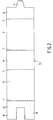
- the wrapper 10 (see also Fig. 2), made of corrugated cardboard in the Figure, has a first end portion 12 with teeth 13 and a second end portion 14 with a forward projecting tongue 15, which tongue 15 projects between the teeth 13, while the tongue 15 and the teeth 13 lie inside the wrapper. This closure of the wrapper is self-fixing.
- the fixation of the closure is further enhanced in that the teeth 13 extend to close to the adjacent folding line 11 of the wrapper 10, as does the tongue 15.
- the tongue 15 is shorter than the teeth 13 (Fig. 2), so that the wrapper can be readily closed.
- the second end portion 14 can already rest on the teeth 13 before the tongue 15 has arrived at the first end portion 12.
- the tongue can be easily brought below the first end portion when the end portions are moved towards one another so as to close the wrapper.
- the trays with cartons containing lamps may be put on the surface 16 of the blank. Then the surfaces 17 are folded upwards about folding lines 11. The surfaces 17 will then enclose the tray 3 with clamping force.
- the first end portion 12 is folded over the side 7' of the cartons 1' and the second end portion 14 is laid on the first end portion. While the tongue 15 is being pressed inwards and passed below the first end portion, the surfaces 17 are moved further towards one another.
- the two packages 1, 3; 1', 3' are then pressed onto one another.
- the surfaces 17 will press against the packages laterally, e.g. against the trays thereof. When the wrapper is closed, it will hold the packages clamped in.
- the tray 3 may be readily folded from the blank of Fig. 3, for example with glue such as, for example, a hot-melt glue. Flaps 5' are present for this purpose.
- the wrapper 20 has portions with reference numerals which are 10 higher than in Figs. 1, 2, i.e. a first 22 and a second end portion 24, each with a first 221, 241 and a second tooth 222, 242 which each become narrower towards a free end thereof.
- a first 22 and a second end portion 24 there is an incision 224, 244 between the teeth 221, 222; 241, 242. The incisions engage one another (Fig. 4).
- a third tooth 223, 243 is present in both end portions 22, 24 between the first and second teeth 221, 222; 241, 242.
- the third tooth 243 in the second end portion 24 is shorter than the first and second teeth 241, 242. This renders it easy to close the wrapper, folded about folding lines 21, as is the case for the wrapper of Fig. 1.
- the narrowing teeth form funnels between themselves, so that the teeth of the first end portion guide the teeth of the second end portion and the incisions engage one another quasi automatically.
- the first and the second end portion 12, 14 and 22, 24, respectively, are remote from the base wall 4, 4' of the tray 3, 3'.
- the units as a result can be well stacked lying on a surface (17 in Fig. 2) of the wrapper with the base walls 4, 4' in vertical position, as shown in Fig. 6.
- the wrappers 10 of the units each have on their closures a seal 42, for example of self-adhesive paper, which shows that the wrapper has not been opened.
- Incisions 38 may have been provided in the upper surface of the stack. These may (see Figs. 7 and 8) define recesses into which flaps of trays may project, whereby it is counteracted that trays can be pressed from the wrapper to the exterior.
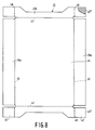
- the tongue 35 has a portion 35a which widens towards the second end portion 34 up to above the interspacing between the teeth 33.
- the tongue 35, and with it the second end portion, is thus centred relative to the first end portion 32 when the wrapper is closed.
- the tongue is laterally clamped in between the teeth during this, which further increases the forces which keep the wrapper closed.
- the wrapper in the Figure has recesses 40 which comprise tongues 39 cut out by means of incisions 38.
- the recesses could cooperate with flaps of a tray. These flaps (cf. Fig. 8) could press the tongues outwards.
- the tongues are flattened, as is an adjoining portion of the wrapper, this being jointly indicated with the reference numeral 40 and shown hatched.
- Such flattened portions are also present in the wrapper of Fig. 6. They may have the result that, as is shown in Fig. 6, apart from the incisions 38 the wrapper hardly shows any sign of the coupling between the wrapper and the trays.
- the tongues have remained inside the wrapper.
- Figs. 7b and c shown that the wrapper has a well-defined, discrete and hard stop 41 for projecting portions of the trays.
- the wrapper shown is designed for accommodating two trays, each filled with two rows of five closed cartons of rectangular block shape holding an electric lamp.
- the tongue 35 is then pressed onto the central carton of a row, the teeth onto the adjoining cartons of the other row. Tongue and teeth are then securely fixed by the cooperating end portions and by the cartons with packed lamps.
- parts have reference numerals which are 40 higher than those of corresponding parts in Fig. 3.
- first the first side walls 45a are folded up about folding lines 46, then the second side walls 45b about folding lines 47, after which the flaps 45' are folded about folding lines 48 against the outsides of the first side walls and fastened thereto.
- the folding lines 48 accordingly, lie farther apart than do the folding lines 46.
- the flaps 45' each have a sturdy end face 45'' which can abut against the stop 41 (Figs. 7b and c) of the wrapper. In the finished packaging, therefore, there is a good coupling between tray and wrapper which counteracts an unauthorized outward displacement of a tray. If this has nevertheless occurred through the use of force, it will be apparent from deformations in the packaging material.
- the second side walls 45b will have flaps 45' which grip around the first side walls 45a and are fastened thereto, while the wrapper 30 has recesses which cooperate with these flaps.
Landscapes
- Engineering & Computer Science (AREA)
- Mechanical Engineering (AREA)
- Cartons (AREA)
- Packages (AREA)
- Packaging Frangible Articles (AREA)
- Details Of Rigid Or Semi-Rigid Containers (AREA)
- Pharmaceuticals Containing Other Organic And Inorganic Compounds (AREA)
Claims (12)
- Verpackungseinheit mit verpackten elektrischen Lampen, mit:Kartons (1) in rechteckiger Blockform, in denen sich je mindestens eine elektrische Lampe (2) befindet;einer Steige (3) mit einer Bodenwand (4) und von dieser Bodenwand ausgehenden, miteinander verbundenen, einander gegenüberliegenden ersten Seitenwänden (5a) und einander gegenüberliegenden zweiten Seitenwänden (5b), wobei diese Steige mit einer Vielzahl in Reihen (6) angeordneter Kartons gefüllt ist; undeiner äußeren Umhüllung (10), die mit einem Verschluß versehen ist und in der die Steige zusammen mit den genannten Kartons untergebracht ist,dadurch gekennzeichnet, daß die äußere Umhüllung (10) ein um parallele Faltlinien (11) gefalteter Wickel ist, der um die Bodenwand (4), um die ersten Seitenwände (5a) der Steige (3) sowie um eine von der Bodenwand abgewandte Seite (7) der Kantons (1) gewickelt ist, und der die Steige (3) mit den Kantons (1) klemmend umschließt.
- Verpackungseinheit nach Anspruch 1, dadurch gekennzeichnet, daß in dem Wickel (10) auf den Kartons (1) der Steige (3) eine zweite mit Kartons (1') gefüllte Steige (3') vorhanden ist.
- Verpackungseinheit nach Anspruch 1 oder 2, dadurch gekennzeichnet, daß der Verschluß einen ersten Endabschnitt (12) des Wickels (10) mit Zähnen (13) und einen zweiten Endabschnitt (14) mit einer nach vom hervorstehenden Zunge (15) umfaßt, welche Zunge (15) zwischen den Zähnen (13) hervorragt, wobei die Zunge (15) und die Zähne (13) innerhalb des Wickels liegen.
- Verpackungseinheit nach Anspruch 3, dadurch gekennzeichnet, daß die Zähne (13) sich nahezu bis zu einer benachbarten Faltlinie (11) des Wickels (10) erstrecken.
- Verpackungseinheit nach Anspruch 3 oder 4, dadurch gekennzeichnet, daß die Zunge (15) kürzer ist als die Zähne (13).
- Verpackungseinheit nach Anspruch 3, 4 oder 5, dadurch gekennzeichnet, daß die Zunge (15) einen Abschnitt (35a) aufweist, der sich zu dem zweiten Endabschnitt (34) hin bis über den Abstand zwischen den Zähnen (33) hinaus erweitert.
- Verpackungseinheit nach Anspruch 1 oder 3, dadurch gekennzeichnet, daß der Verschluß in einer von der Bodenwand (4) der Steige (3) abgewandten Flache vorhanden ist.
- Verpackungseinheit nach Anspruch 1 oder 3, dadurch gekennzeichnet, daß sich über dem Verschluß eine Versiegelung (42) befindet.
- Verpackungseinheit nach Anspruch 9, dadurch gekennzeichnet, daß die ersten Seitenwände (45a) und der Wickel (30) hervorstehende Abschnitte (45') und Aussparungen (40) aufweisen, die ineinandergreifen.
- Verpackungseinheit nach Anspruch 9, dadurch gekennzeichnet, daß die zweiten Seitenwände (45b) Laschen (45') haben, die um die ersten Seitenwände (45a) greifen und daran befestigt sind und daß der Wickel (30) damit zusammenarbeitende Aussparungen (40) aufweist.
- Verpackungseinheit nach Anspruch 10, dadurch gekennzeichnet, daß die Aussparungen (40) herausgeschnittene Zungen (39) aufweisen.
- Verpackungseinheit nach Anspruch 11, dadurch gekennzeichnet, daß die Laschen (39) abgeplattet sind.
Applications Claiming Priority (4)
| Application Number | Priority Date | Filing Date | Title |
|---|---|---|---|
| NL9201462 | 1992-08-17 | ||
| NL9201462A NL9201462A (nl) | 1992-08-17 | 1992-08-17 | Verpakkingseenheid met verpakte elektrische lampen. |
| EP92203343 | 1992-10-30 | ||
| EP92203343 | 1992-10-30 |
Publications (2)
| Publication Number | Publication Date |
|---|---|
| EP0583840A1 EP0583840A1 (de) | 1994-02-23 |
| EP0583840B1 true EP0583840B1 (de) | 1997-01-22 |
Family
ID=26131768
Family Applications (1)
| Application Number | Title | Priority Date | Filing Date |
|---|---|---|---|
| EP93202410A Expired - Lifetime EP0583840B1 (de) | 1992-08-17 | 1993-08-17 | Verpackung mit elektrischen Lampen |
Country Status (11)
| Country | Link |
|---|---|
| US (1) | US5555979A (de) |
| EP (1) | EP0583840B1 (de) |
| AT (1) | ATE148064T1 (de) |
| AU (1) | AU665850B2 (de) |
| BE (1) | BE1006229A6 (de) |
| DE (2) | DE9300949U1 (de) |
| ES (1) | ES2099370T3 (de) |
| FI (1) | FI933569A7 (de) |
| FR (1) | FR2685297B3 (de) |
| NO (1) | NO932881L (de) |
| NZ (1) | NZ248390A (de) |
Families Citing this family (6)
| Publication number | Priority date | Publication date | Assignee | Title |
|---|---|---|---|---|
| USD393800S (en) | 1996-04-22 | 1998-04-28 | U.S. Philips Corporation | Packaging for light bulbs and lamps |
| SE506964C2 (sv) * | 1996-05-30 | 1998-03-09 | Rieber & Soen As | Förpackning för glödlampor avsedda att staplas i 90 grader vinkel mot varandra samt sätt att använda en sådan |
| USD480637S1 (en) | 2003-01-30 | 2003-10-14 | Tsi Prime | Light kit package |
| DE102005013147A1 (de) * | 2005-03-22 | 2006-09-28 | Robert Bosch Gmbh | Verpackungseinheit, insbesondere für Wischblätter |
| US20070251985A1 (en) * | 2006-04-26 | 2007-11-01 | David Boase | Blank and an open-top carton constructed therefrom |
| USD685649S1 (en) * | 2010-08-04 | 2013-07-09 | Global Sourcing Solutions, LLC | Box |
Family Cites Families (19)
| Publication number | Priority date | Publication date | Assignee | Title |
|---|---|---|---|---|
| US1888855A (en) * | 1929-12-21 | 1932-11-22 | Gen Electric | Package for incandescent lamps and similar articles |
| US2912104A (en) * | 1958-09-22 | 1959-11-10 | New Haven Board And Carton Com | Packages of cylindrical articles |
| DK107928C (da) * | 1965-10-11 | 1967-07-17 | Unilever Nv | Emballage af karton for i det mindste to lag i højden stablede beholdere. |
| CA952866A (en) * | 1971-06-04 | 1974-08-13 | William B. Hopkins | Light bulb carton holder |
| FR2139874B1 (de) * | 1972-05-10 | 1974-11-08 | Huault Jean | |
| GB1512521A (en) * | 1975-07-29 | 1978-06-01 | Metal Box Co Ltd | Packaging food products |
| US4058211A (en) * | 1976-08-10 | 1977-11-15 | Westinghouse Electric Corporation | Electric lamp bulb package and sleeve component therefrom |
| JPS548095A (en) * | 1977-06-18 | 1979-01-22 | Focke & Co | Thin film wrapper and method and device for making said wrapper |
| US4180164A (en) * | 1978-10-25 | 1979-12-25 | Voltarc Tubes, Inc. | Packaging arrangement for U-shaped fluorescent lamps |
| CH643204A5 (de) * | 1980-02-15 | 1984-05-30 | Sig Schweiz Industrieges | Sammelpackung, verfahren zur herstellung derselben und verwendung. |
| GB2137953B (en) * | 1983-03-17 | 1986-04-30 | Europack Eng Co | Producing packs of overwrapped goods in trays |
| DE8403230U1 (de) * | 1984-02-04 | 1984-03-29 | Philips Patentverwaltung Gmbh, 2000 Hamburg | Verpackungseinheit fuer Gluehlampen |
| US4744464A (en) * | 1985-10-31 | 1988-05-17 | General Electric Company | Ribbon blown glass article transport |
| US4708284A (en) * | 1986-02-12 | 1987-11-24 | Federal Paper Board Co., Inc. | Lock arrangement |
| FR2626256B1 (fr) * | 1988-01-22 | 1990-05-04 | Nicollet Hugues Sa | Ensemble de conditionnement, notamment pour articles en nombre a delivrer par groupe |
| US4878612A (en) * | 1988-04-18 | 1989-11-07 | Manville Corporation | Wrap-around carton with locking flap connection |
| US4844328A (en) * | 1988-04-29 | 1989-07-04 | Manville Corporation | Wrap-around carton with flange-receiving slots |
| US4860943A (en) * | 1988-04-29 | 1989-08-29 | Manville Corporation | Wrap-around carton locking means |
| US5180100A (en) * | 1992-05-20 | 1993-01-19 | Oak Tree Packaging Corporation | Wraparound carton lock |
-
1993
- 1993-01-15 BE BE9300037A patent/BE1006229A6/fr not_active IP Right Cessation
- 1993-01-25 DE DE9300949U patent/DE9300949U1/de not_active Expired - Lifetime
- 1993-02-03 FR FR9301181A patent/FR2685297B3/fr not_active Expired - Fee Related
- 1993-08-06 US US08/103,477 patent/US5555979A/en not_active Expired - Fee Related
- 1993-08-12 FI FI933569A patent/FI933569A7/fi not_active Application Discontinuation
- 1993-08-12 NZ NZ248390A patent/NZ248390A/en unknown
- 1993-08-13 NO NO932881A patent/NO932881L/no unknown
- 1993-08-16 AU AU44678/93A patent/AU665850B2/en not_active Ceased
- 1993-08-17 EP EP93202410A patent/EP0583840B1/de not_active Expired - Lifetime
- 1993-08-17 AT AT93202410T patent/ATE148064T1/de not_active IP Right Cessation
- 1993-08-17 DE DE69307626T patent/DE69307626T2/de not_active Expired - Fee Related
- 1993-08-17 ES ES93202410T patent/ES2099370T3/es not_active Expired - Lifetime
Also Published As
| Publication number | Publication date |
|---|---|
| DE9300949U1 (de) | 1993-03-18 |
| NO932881L (no) | 1994-02-18 |
| FI933569A0 (fi) | 1993-08-12 |
| FR2685297B3 (fr) | 1993-11-05 |
| AU4467893A (en) | 1994-02-24 |
| EP0583840A1 (de) | 1994-02-23 |
| ES2099370T3 (es) | 1997-05-16 |
| DE69307626T2 (de) | 1997-07-17 |
| US5555979A (en) | 1996-09-17 |
| ATE148064T1 (de) | 1997-02-15 |
| NZ248390A (en) | 1994-12-22 |
| BE1006229A6 (fr) | 1994-06-14 |
| FR2685297A3 (fr) | 1993-06-25 |
| NO932881D0 (no) | 1993-08-13 |
| AU665850B2 (en) | 1996-01-18 |
| FI933569A7 (fi) | 1994-02-18 |
| DE69307626D1 (de) | 1997-03-06 |
Similar Documents
| Publication | Publication Date | Title |
|---|---|---|
| US5035323A (en) | Shipper display | |
| EP1206393B1 (de) | Transport- und präsentationskarton | |
| US7000803B2 (en) | Contoured carton with dispenser | |
| US4641746A (en) | Tray-type shipping and display container | |
| US4605128A (en) | Dispensing carrier box and blank | |
| KR0185708B1 (ko) | 손잡이를 갖춘 포장상자 | |
| US20020070145A1 (en) | Shipper and display carton | |
| MXPA01011152A (es) | Portador de articulo con ventanas de extremo. | |
| US5857570A (en) | Primary and secondary packaging system for beverage products | |
| US20180282039A1 (en) | Clip-in carrier package for beverage cans | |
| KR200492642Y1 (ko) | 포장상자와 물품 디스펜서 | |
| US4946037A (en) | Package having supported gabletop containers for two part composition | |
| MX2008012613A (es) | Distribuidor de paquetes. | |
| US2074477A (en) | Carton and blank for forming the same | |
| US4895255A (en) | Shrink wrapped shipping bundle of blister packages for windshield wipers | |
| US5555979A (en) | Packing unit with packed electric lamps | |
| EP0907580B1 (de) | Flaschentragebehälter | |
| GB2088830A (en) | Tear-open package | |
| GB2198709A (en) | Carton-forming blank | |
| US6105759A (en) | Folding box for receiving a rod-like article | |
| US4860888A (en) | Shipping and handling container for two part composition | |
| JP4211238B2 (ja) | 包装容器 | |
| EP0168098A2 (de) | Tablettartige Transport- und Schaustellungsbehälter | |
| JP2000281048A (ja) | 包装箱 | |
| JP2001206350A (ja) | 包装箱 |
Legal Events
| Date | Code | Title | Description |
|---|---|---|---|
| PUAI | Public reference made under article 153(3) epc to a published international application that has entered the european phase |
Free format text: ORIGINAL CODE: 0009012 |
|
| AK | Designated contracting states |
Kind code of ref document: A1 Designated state(s): AT BE CH DE DK ES FR GB GR IE IT LI NL PT SE |
|
| RAP1 | Party data changed (applicant data changed or rights of an application transferred) |
Owner name: N.V. PHILIPS' GLOEILAMPENFABRIEKEN |
|
| 17P | Request for examination filed |
Effective date: 19940728 |
|
| GRAG | Despatch of communication of intention to grant |
Free format text: ORIGINAL CODE: EPIDOS AGRA |
|
| 17Q | First examination report despatched |
Effective date: 19960312 |
|
| GRAH | Despatch of communication of intention to grant a patent |
Free format text: ORIGINAL CODE: EPIDOS IGRA |
|
| GRAH | Despatch of communication of intention to grant a patent |
Free format text: ORIGINAL CODE: EPIDOS IGRA |
|
| GRAA | (expected) grant |
Free format text: ORIGINAL CODE: 0009210 |
|
| AK | Designated contracting states |
Kind code of ref document: B1 Designated state(s): AT BE CH DE DK ES FR GB GR IE IT LI NL PT SE |
|
| PG25 | Lapsed in a contracting state [announced via postgrant information from national office to epo] |
Ref country code: NL Free format text: LAPSE BECAUSE OF FAILURE TO SUBMIT A TRANSLATION OF THE DESCRIPTION OR TO PAY THE FEE WITHIN THE PRESCRIBED TIME-LIMIT Effective date: 19970122 Ref country code: LI Effective date: 19970122 Ref country code: GR Free format text: LAPSE BECAUSE OF FAILURE TO SUBMIT A TRANSLATION OF THE DESCRIPTION OR TO PAY THE FEE WITHIN THE PRESCRIBED TIME-LIMIT Effective date: 19970122 Ref country code: DK Effective date: 19970122 Ref country code: CH Effective date: 19970122 Ref country code: BE Effective date: 19970122 Ref country code: AT Effective date: 19970122 |
|
| REF | Corresponds to: |
Ref document number: 148064 Country of ref document: AT Date of ref document: 19970215 Kind code of ref document: T |
|
| REG | Reference to a national code |
Ref country code: CH Ref legal event code: EP |
|
| REF | Corresponds to: |
Ref document number: 69307626 Country of ref document: DE Date of ref document: 19970306 |
|
| REG | Reference to a national code |
Ref country code: IE Ref legal event code: FG4D Free format text: 71715 |
|
| ITF | It: translation for a ep patent filed | ||
| PG25 | Lapsed in a contracting state [announced via postgrant information from national office to epo] |
Ref country code: SE Effective date: 19970422 Ref country code: PT Effective date: 19970422 |
|
| ET | Fr: translation filed | ||
| REG | Reference to a national code |
Ref country code: ES Ref legal event code: FG2A Ref document number: 2099370 Country of ref document: ES Kind code of ref document: T3 |
|
| NLV1 | Nl: lapsed or annulled due to failure to fulfill the requirements of art. 29p and 29m of the patents act | ||
| REG | Reference to a national code |
Ref country code: CH Ref legal event code: PL |
|
| PG25 | Lapsed in a contracting state [announced via postgrant information from national office to epo] |
Ref country code: IE Free format text: LAPSE BECAUSE OF NON-PAYMENT OF DUE FEES Effective date: 19970817 |
|
| PLBE | No opposition filed within time limit |
Free format text: ORIGINAL CODE: 0009261 |
|
| 26N | No opposition filed | ||
| REG | Reference to a national code |
Ref country code: FR Ref legal event code: CD |
|
| REG | Reference to a national code |
Ref country code: ES Ref legal event code: PC2A |
|
| REG | Reference to a national code |
Ref country code: GB Ref legal event code: IF02 |
|
| PGFP | Annual fee paid to national office [announced via postgrant information from national office to epo] |
Ref country code: GB Payment date: 20030829 Year of fee payment: 11 |
|
| PGFP | Annual fee paid to national office [announced via postgrant information from national office to epo] |
Ref country code: DE Payment date: 20031015 Year of fee payment: 11 |
|
| PGFP | Annual fee paid to national office [announced via postgrant information from national office to epo] |
Ref country code: ES Payment date: 20040803 Year of fee payment: 12 |
|
| PG25 | Lapsed in a contracting state [announced via postgrant information from national office to epo] |
Ref country code: GB Free format text: LAPSE BECAUSE OF NON-PAYMENT OF DUE FEES Effective date: 20040817 |
|
| PGFP | Annual fee paid to national office [announced via postgrant information from national office to epo] |
Ref country code: FR Payment date: 20040830 Year of fee payment: 12 |
|
| PG25 | Lapsed in a contracting state [announced via postgrant information from national office to epo] |
Ref country code: DE Free format text: LAPSE BECAUSE OF NON-PAYMENT OF DUE FEES Effective date: 20050301 |
|
| GBPC | Gb: european patent ceased through non-payment of renewal fee |
Effective date: 20040817 |
|
| PG25 | Lapsed in a contracting state [announced via postgrant information from national office to epo] |
Ref country code: IT Free format text: LAPSE BECAUSE OF NON-PAYMENT OF DUE FEES Effective date: 20050817 |
|
| PG25 | Lapsed in a contracting state [announced via postgrant information from national office to epo] |
Ref country code: ES Free format text: LAPSE BECAUSE OF NON-PAYMENT OF DUE FEES Effective date: 20050818 |
|
| PG25 | Lapsed in a contracting state [announced via postgrant information from national office to epo] |
Ref country code: FR Free format text: LAPSE BECAUSE OF NON-PAYMENT OF DUE FEES Effective date: 20060428 |
|
| REG | Reference to a national code |
Ref country code: FR Ref legal event code: ST Effective date: 20060428 |
|
| REG | Reference to a national code |
Ref country code: ES Ref legal event code: FD2A Effective date: 20050818 |