EP0583934A2 - Connecteur de câbles à haute fréquence - Google Patents
Connecteur de câbles à haute fréquence Download PDFInfo
- Publication number
- EP0583934A2 EP0583934A2 EP93306327A EP93306327A EP0583934A2 EP 0583934 A2 EP0583934 A2 EP 0583934A2 EP 93306327 A EP93306327 A EP 93306327A EP 93306327 A EP93306327 A EP 93306327A EP 0583934 A2 EP0583934 A2 EP 0583934A2
- Authority
- EP
- European Patent Office
- Prior art keywords
- connector
- shield
- shielded
- spring clip
- housing
- Prior art date
- Legal status (The legal status is an assumption and is not a legal conclusion. Google has not performed a legal analysis and makes no representation as to the accuracy of the status listed.)
- Granted
Links
Images










Classifications
-
- H—ELECTRICITY
- H01—ELECTRIC ELEMENTS
- H01R—ELECTRICALLY-CONDUCTIVE CONNECTIONS; STRUCTURAL ASSOCIATIONS OF A PLURALITY OF MUTUALLY-INSULATED ELECTRICAL CONNECTING ELEMENTS; COUPLING DEVICES; CURRENT COLLECTORS
- H01R24/00—Two-part coupling devices, or either of their cooperating parts, characterised by their overall structure
- H01R24/38—Two-part coupling devices, or either of their cooperating parts, characterised by their overall structure having concentrically or coaxially arranged contacts
- H01R24/40—Two-part coupling devices, or either of their cooperating parts, characterised by their overall structure having concentrically or coaxially arranged contacts specially adapted for high frequency
-
- H—ELECTRICITY
- H01—ELECTRIC ELEMENTS
- H01R—ELECTRICALLY-CONDUCTIVE CONNECTIONS; STRUCTURAL ASSOCIATIONS OF A PLURALITY OF MUTUALLY-INSULATED ELECTRICAL CONNECTING ELEMENTS; COUPLING DEVICES; CURRENT COLLECTORS
- H01R13/00—Details of coupling devices of the kinds covered by groups H01R12/70 or H01R24/00 - H01R33/00
- H01R13/648—Protective earth or shield arrangements on coupling devices, e.g. anti-static shielding
- H01R13/658—High frequency shielding arrangements, e.g. against EMI [Electro-Magnetic Interference] or EMP [Electro-Magnetic Pulse]
- H01R13/6581—Shield structure
- H01R13/6582—Shield structure with resilient means for engaging mating connector
- H01R13/6583—Shield structure with resilient means for engaging mating connector with separate conductive resilient members between mating shield members
-
- H—ELECTRICITY
- H01—ELECTRIC ELEMENTS
- H01R—ELECTRICALLY-CONDUCTIVE CONNECTIONS; STRUCTURAL ASSOCIATIONS OF A PLURALITY OF MUTUALLY-INSULATED ELECTRICAL CONNECTING ELEMENTS; COUPLING DEVICES; CURRENT COLLECTORS
- H01R13/00—Details of coupling devices of the kinds covered by groups H01R12/70 or H01R24/00 - H01R33/00
- H01R13/648—Protective earth or shield arrangements on coupling devices, e.g. anti-static shielding
- H01R13/658—High frequency shielding arrangements, e.g. against EMI [Electro-Magnetic Interference] or EMP [Electro-Magnetic Pulse]
- H01R13/6591—Specific features or arrangements of connection of shield to conductive members
- H01R13/6592—Specific features or arrangements of connection of shield to conductive members the conductive member being a shielded cable
-
- H—ELECTRICITY
- H01—ELECTRIC ELEMENTS
- H01R—ELECTRICALLY-CONDUCTIVE CONNECTIONS; STRUCTURAL ASSOCIATIONS OF A PLURALITY OF MUTUALLY-INSULATED ELECTRICAL CONNECTING ELEMENTS; COUPLING DEVICES; CURRENT COLLECTORS
- H01R2103/00—Two poles
-
- H—ELECTRICITY
- H01—ELECTRIC ELEMENTS
- H01R—ELECTRICALLY-CONDUCTIVE CONNECTIONS; STRUCTURAL ASSOCIATIONS OF A PLURALITY OF MUTUALLY-INSULATED ELECTRICAL CONNECTING ELEMENTS; COUPLING DEVICES; CURRENT COLLECTORS
- H01R2105/00—Three poles
-
- H—ELECTRICITY
- H01—ELECTRIC ELEMENTS
- H01R—ELECTRICALLY-CONDUCTIVE CONNECTIONS; STRUCTURAL ASSOCIATIONS OF A PLURALITY OF MUTUALLY-INSULATED ELECTRICAL CONNECTING ELEMENTS; COUPLING DEVICES; CURRENT COLLECTORS
- H01R24/00—Two-part coupling devices, or either of their cooperating parts, characterised by their overall structure
- H01R24/38—Two-part coupling devices, or either of their cooperating parts, characterised by their overall structure having concentrically or coaxially arranged contacts
- H01R24/40—Two-part coupling devices, or either of their cooperating parts, characterised by their overall structure having concentrically or coaxially arranged contacts specially adapted for high frequency
- H01R24/56—Two-part coupling devices, or either of their cooperating parts, characterised by their overall structure having concentrically or coaxially arranged contacts specially adapted for high frequency specially adapted to a specific shape of cables, e.g. corrugated cables, twisted pair cables, cables with two screens or hollow cables
- H01R24/562—Cables with two screens
Definitions
- the invention is directed to a high frequency electrical connector for a twin axial or a coaxial cable.
- One shielded coaxial connector system is shown in European Patent Application O 446 980 where a shielded coaxial contact surrounds a dielectric body where the shield is electrically grounded to a shield of an electrical cable.
- the outer shield includes contact members formed integrally therewith for making contact with a mating pin or with an adjacent shield of an adjacent contact.
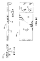
- a high density shielded electrical connector comprising at least two inner insulating housings separately surrounded by an outer shielding member, and having inner signal contacts, the outer shielding members being common together by way of a grounding spring clip which also defines a mating contact in the same direction as that of said signal contacts.
- a connector subassembly is shown generally at 2 comprised of an insulating housing portion 4, a pair of electrical terminals 6 and a cover portion 8.
- the terminal pairs are shown as a stamped and formed set of electrical terminals having base portions 10 forming rear wire receiving surfaces 12 and forward contact portions 14.
- the contact portions are formed by two contact arms 16 and 18 where the contact arm 18 extends forwardly from the base portion 10 while contact arm 16 is folded over about an integral tab portion 20 to place the contact arms one above the other.
- the contact arms are radiused at their front edges for example at 22, 24 to form lead-in sections for a mating tab in a mating connector.
- the terminal pair 6 include a strengthening bar 26 integrally formed between the two base portions 10 for rigidity purposes, but is stamped away prior to insertion in the housing.
- the housing member 4 includes two side by side channel-like openings 30 for receiving the terminals 6 therein.
- the housings include a reduced thickness portion at 32 which receives the retaining barbs 27 located along the side edges of the base portions 10, thereby holding the terminals in position within the housing.
- the channel-like openings open through the rear face 34 of the connector housing through openings 36.
- the housing 4 further includes a front mating face 38 providing pin receiving openings at 40 for receiving the pins of a mating electrical connector (not shown herein).
- the cover member includes an inner surface 44 having recessed edges 46 profiled for receipt on top edges of the side walls 31. Alignment of the cover member 8 with the housing member 4 is insured by cooperating apertures 48 in the cover part which cooperate with a plurality of studs 50 along the separating rib 33 of the housing portion. Furthermore, retention of the terminals 6 within the housing is insured by way of locking bars 52 which extend downwardly from the inner surface 44 of the cover member 8, and when the cover is in the fully closed position, are locked behind the contact arms 16.
- the forward end of the cover 8 includes wall portions 55 which cooperate with the openings 40 to form a closed pin-receiving opening. As shown in Figures 3 and 4, the cover member 8 is shown in the closed position with a raised section 58 extending above the upper surface 60 of the cover portion 8.
- the connector 2 has the terminal platform portions 6 extending outwardly of the housing 4 profiled for receiving the conductors 61 of a twinax cable 62.
- the cable 62 includes an outer insulating jacket 64 which is stripped partially to expose the conductive shield 66, while the insulation 68 of the individual insulated conductors 61 is stripped to expose the conductors 61, such that they are positioned on top of the platforms 6, where they can be soldered or otherwise welded in place.
- an outer shield member is shown generally at 70, which is stamped and formed from a flat sheet of metal material, to include a base portion shown at 72 having folded up sidewalls 74 and folded over split cover parts 76 having an axial seam at 78. Intermediate the cover parts 76 and formed by way of the seam 78 is a rectangular opening at 80 which is profiled to receive the raised section 58 of the cover part 8.
- Extending integrally from the sidewalls 74 are crimp portions 82 profiled for crimping to the braid 66 of the twinax cable 62.
- strain relief crimp arms 84 profiled to crimp around the outer jack portion 64 of the twinax connector.
- the assembly shown in Figure 4 is insertable through a rear entry portion of the shield member 70, to the position shown in Figure 6.
- the side walls 74 are overstamped such that upon insertion of the housing member 4, the seam 78 is slightly opened such that edges 89 of the opening 80 are in contact with the raised portion 58.
- the shield arms 82 are shown in position to be crimped to the ground shield portion 66 of the cable 62 while the strain relief 84 are profiled to grip the outer jacket 64.
- FIG. 7 two shielded housings are shown at 88 spaced apart from one another and disposed in a parallel manner.
- a grounding spring clip 90 is positioned intermediate the two shielded housings 88 whereby the outer shields of the two shielded connectors 88 are commoned together.
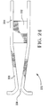
- the grounding spring clip 90 is shown as a stamped and formed U-shaped member formed from upper and lower plate portions 91 and 92 ( Figure 9) stamped about a bight portion 94.
- the plate portions 91 and 92 are stamped into individual contact arms 96 and 98 having individual contact portions 100 and 102 extending forwardly therefrom.
- the contact portions 100 and 102 are spaced apart by a dimension of 2mm such that the two contact portions can connect pins on a 2mm grid pattern.
- the contact arm portions 96, 98 and 100, 102 are formed to project outwardly at 104, 106 to form contact portions to common the adjacent shield members, as shown in Figure 7.
- the contact arms 100 and 102 are constricted at the front portion to form contact surfaces 108 and 110 for mating with a complementary pin field. This is shown best in Figure 7 where pins 120 and 122 are shown in a spaced apart manner and are profiled to be received within the contacts formed at 108 and 110.
- an outer housing module is shown at 130 including channels 132 and 134 which are profiled for receiving side by side shielded modules.
- the housing 130 includes an opening intermediate the openings 132 and 134 for receiving the grounding spring clip therethrough which can be seated in a permanent position.
- the shielded connector members 88 can be insertable and removable into and out of the channels 132, 134.
- the outer housing 130 together with the installed grounding spring clip 90 can be shipped to the customer while the housing 4, cover 8 and terminals 6 can be assembled in a configuration shown in Figure 3, and the end user can assemble the cable 62 to the connector 2, later assemble the ground shield 70 and install the shielded subassemblies 88 within the housing 130 into contact with the intermediate spring grounding clip 90.
- the housing 130 would include a front face 140 having apertures in alignment with the openings 40 such that the mating pins can be received within the connector housing 130 and into contact with the contact portions 22, 24, ( Figure 1).
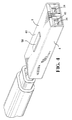
- a shielded connector is shown generally at 202 comprising an inner housing part 204 having terminals 206 positioned therein and having and upper cover part 208 enclosing the terminal and the inner housing 204.
- An outer shield member is shown generally at 210 having a centrally disposed shield contact 212 positioned within a central recess 214 formed by the outer shield member 210.
- the connector is profiled for terminating a twinax cable shown generally at 216 comprising an outer insulative cover 218, an inner shield at 220, a signal conductor at 222 and a centrally disposed drain wire 224.
- the preferred embodiment of the inner housing 204 is shown in greater detail as including a front mating face 230, side walls 232 and an end wall 234.
- a rear wire terminating section is shown at 236 including channels at 238 which open into cavities at 240 which are defined by opposed side walls 242 and 244 and a recessed platform surface at 246.
- the side walls 244 are defined by a central upstanding platform portion at 250 which has a rear surface 252 which is recessed from the end wall 244.
- the housing 204 further comprises forward terminal receiving passageways at 255 which include pin receiving openings at 256 which open into the passageways 255 where each passageway 255 includes side wall surfaces 257, 258 and 259, on one side thereof and side surfaces 260 which extend forwardly and terminate within recess portions shown at 262.
- the housing 204 includes a major top surface shown at 265 and a lower surface shown at 266. Aligning posts 268 extend upwardly from the major surfaces 265 and could be formed in a multitude of ways, for example with two side by side lugs 268 as shown in Figure 13 or as three in line lugs as shown in Figure 11.
- the top cover part 208 is shown best in Figures 16 through 18 as including an inner surface at 270 having apertures 272 therein which match the lugs 268 on the housing portion 204.
- the signal contact 206 is shown as including a beam portion 280 having a transversely situated contact pad 282 thereon, the beam portion 280 extending forwardly through a right angled section 284 and a further beam portion 286 extending forwardly, a cantilever beam portion is shown at 288 which disposes a contact portion at 290 towards a free end portion 292. It should be appreciated that two such contacts 206 are positioned in one single housing 204, although these terminals are not identical, they are mirror images of one another.
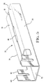
- an outer shield member is shown at 300, which is formed of a unitary piece of metal material, and is formed with a base wall at 302 whereby the base material is formed at right angles thereby forming side walls 304 and further folded over to form top coverparts at 306.
- the top cover parts are folded downwardly towards the base section having two inner side walls at 308 thereby forming two shielded enclosures at 310.
- the inner side wall portions 308 include folded over tab portions 312 and 314, where the tab portions 314 are interrupted by an opening 316 which overlies an opening 318 in the base portion.
- a nest 320 is formed for a ground contact as will be described herein.
- a ground contact is shown at 330 including a lower base portion 332 having folded up side edges 334 which form cantilever beam sections 336 forwardly to form a contact at 338.
- the shield contact 330 is shown disposed within the shield member 210 within the cavity 214 defined between adjacent inner side walls 318 of the shield.
- the lower base section 332 is located in the nest section 320, positioned between the tab sections 312 and 314, and preferably the base section 332 is fastened to the base wall 302 of the shield member 210 by a welding, such as spot welding.
- the ground contact 330 has the contact section 338 disposed outwardly of the shield member whereas two shielding enclosures 310 flank either side of the terminal 330.
- the terminals 206 are positioned within the housing 204 such that the beam portion 286 is positioned in the channels 238, which disposes the beam portion 280 adjacent to the outer walls 242, thereby disposing the contact pad 282 on the platform surface 246. This also disposes the beam portion 286 forwardly from the channels 238 such that the cantilever beam 288 extends obliquely across the passageway 255 such that the contact surface 290 is positioned adjacent to side wall portions 257 and 258, while the free end portion 292 is disposed behind the corner at 262. As shown in Figure 11, the housings 204 can then be closed by placing the cover 208 over the top and the housings 204 can be slidably received in the shielding enclosure 310.
- top cover walls 306 of the shield member 300 are shorter than the base wall 302, as best shown in Figure 21, such that a portion of the base wall 302 is exposed from an upper side of the shield member 300. This positions the housing member within the shielding enclosure to a position shown in Figure 28, such that the contact pads 282 are accessible from a top portion of the shield member 300.
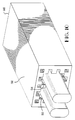
- the connector is assembled by positioning the twinaxial cable 216, as prepared as shown in Figure 11, over the connector as assembled in Figure 28, with the signal contacts 222 positioned over adjacent contact pads 282, and with the drain wire 224 disposed between the contact pads. All three conductors can then be welded to their associated conductive part which electrically connects the twinax cable 216 to the connector assembly. As shown in Figure 29, an overmoulding web shown best at 350 can be positioned over the inner housing portions, and in particular over the rear section of the housing 204, to enclose the twinax cables 216 therein.
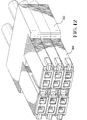
- the outer moulded web 350 includes a keyed opening at 352, which allows several housings to be placed one above the other as shown in Figure 12, with a pin or post positioned through aligned keyed openings 352 to retain them together.
- key members 360 can be attached to the housing members 204, which allow polarized connection to a mating connector.
Landscapes
- Details Of Connecting Devices For Male And Female Coupling (AREA)
Applications Claiming Priority (4)
| Application Number | Priority Date | Filing Date | Title |
|---|---|---|---|
| GB929217546A GB9217546D0 (en) | 1992-08-18 | 1992-08-18 | High frequency cable connector |
| GB9217546 | 1992-08-18 | ||
| GB9306399 | 1993-03-26 | ||
| GB939306399A GB9306399D0 (en) | 1993-03-26 | 1993-03-26 | High frequency cable connector |
Publications (3)
| Publication Number | Publication Date |
|---|---|
| EP0583934A2 true EP0583934A2 (fr) | 1994-02-23 |
| EP0583934A3 EP0583934A3 (fr) | 1995-02-08 |
| EP0583934B1 EP0583934B1 (fr) | 1999-04-21 |
Family
ID=26301455
Family Applications (1)
| Application Number | Title | Priority Date | Filing Date |
|---|---|---|---|
| EP93306327A Expired - Lifetime EP0583934B1 (fr) | 1992-08-18 | 1993-08-11 | Connecteur de câbles à haute fréquence |
Country Status (4)
| Country | Link |
|---|---|
| US (1) | US5632634A (fr) |
| EP (1) | EP0583934B1 (fr) |
| JP (1) | JP3415889B2 (fr) |
| DE (1) | DE69324536T2 (fr) |
Cited By (10)
| Publication number | Priority date | Publication date | Assignee | Title |
|---|---|---|---|---|
| US5766036A (en) * | 1996-10-11 | 1998-06-16 | Molex Incorporated | Impedance matched cable assembly having latching subassembly |
| EP0793311A3 (fr) * | 1996-03-01 | 1998-07-29 | Molex Incorporated | Système pour terminer le blindage d'un câble à grande vitesse |
| WO1998048488A1 (fr) * | 1997-04-17 | 1998-10-29 | Societe De Fabrication Industrielle Et Mecanique - Sofim | Connecteur electrique pour frequences elevees |
| US5830010A (en) * | 1996-10-11 | 1998-11-03 | Molex Incorporated | Impedance matched cable assembly |
| AU699118B2 (en) * | 1997-02-20 | 1998-11-19 | Gec Alsthom Transport Sa | A method and a device for grounding the shielding braids of shielded cables |
| EP0793306A3 (fr) * | 1996-03-01 | 1998-11-25 | Molex Incorporated | Système de terminaison d'écran d'un câble à grande vitesse |
| NL1022159C2 (nl) * | 2002-12-13 | 2004-06-15 | Framatome Connectors Int | Kabelconnector en methode voor het vervaardigen van een kabelconnector. |
| US6843657B2 (en) | 2001-01-12 | 2005-01-18 | Litton Systems Inc. | High speed, high density interconnect system for differential and single-ended transmission applications |
| US6910897B2 (en) | 2001-01-12 | 2005-06-28 | Litton Systems, Inc. | Interconnection system |
| EP2789054A1 (fr) * | 2011-12-08 | 2014-10-15 | Tyco Electronics Corporation | Connecteur d'en-tête de câble |
Families Citing this family (78)
| Publication number | Priority date | Publication date | Assignee | Title |
|---|---|---|---|---|
| US5509827A (en) * | 1994-11-21 | 1996-04-23 | Cray Computer Corporation | High density, high bandwidth, coaxial cable, flexible circuit and circuit board connection assembly |
| DE19732284C2 (de) * | 1997-07-26 | 2001-11-08 | Erni Elektroapp | Steckverbindung für eine Leiterplattenschaltung elektronischer Bauelemente |
| GB9721838D0 (en) * | 1997-10-16 | 1997-12-17 | Smiths Industries Plc | Electrical connection |
| US6471547B1 (en) | 1999-06-01 | 2002-10-29 | John T. Venaleck | Electrical connector for high density signal interconnections and method of making the same |
| US6524135B1 (en) | 1999-09-20 | 2003-02-25 | 3M Innovative Properties Company | Controlled impedance cable connector |
| US6203369B1 (en) | 1999-10-25 | 2001-03-20 | 3M Innovative Properties Company | High frequency cable connector having low self-inductance ground return paths |
| US6203376B1 (en) * | 1999-12-15 | 2001-03-20 | Molex Incorporated | Cable wafer connector with integrated strain relief |
| US6261127B1 (en) | 2000-01-24 | 2001-07-17 | Molex Incorporated | High speed, shielded cable assembly |
| US6498506B1 (en) * | 2000-07-26 | 2002-12-24 | Gore Enterprise Holdings, Inc. | Spring probe assemblies |
| CA2361875A1 (fr) * | 2000-11-14 | 2002-05-14 | Fci Americas Technology, Inc. | Connecteurs de cartes a haute vitesse |
| US6979202B2 (en) | 2001-01-12 | 2005-12-27 | Litton Systems, Inc. | High-speed electrical connector |
| JP3564555B2 (ja) | 2001-03-05 | 2004-09-15 | 日本航空電子工業株式会社 | 高速ディファレンシャル信号伝送用コネクタ |
| JP2003086308A (ja) * | 2001-09-13 | 2003-03-20 | Auto Network Gijutsu Kenkyusho:Kk | シールドコネクタ |
| KR100434230B1 (ko) * | 2002-03-26 | 2004-06-04 | 한국몰렉스 주식회사 | 고속통신용 케이블 커넥터 어셈블리 |
| US6997753B2 (en) * | 2003-10-22 | 2006-02-14 | Gore Enterprise Holdings, Inc. | Apparatus, system and method for improved calibration and measurement of differential devices |
| WO2005053102A2 (fr) * | 2003-11-21 | 2005-06-09 | Ohio Associated Enterprises Llc | Ensemble cable et procede de fabrication |
| TWM251379U (en) * | 2004-02-11 | 2004-11-21 | Comax Technology Inc | Grounding structure of electrical connector |
| US7004793B2 (en) * | 2004-04-28 | 2006-02-28 | 3M Innovative Properties Company | Low inductance shielded connector |
| US7484989B2 (en) * | 2006-11-29 | 2009-02-03 | Ohio Associated Enterprises, Llc | Low friction cable assembly latch |
| US7744403B2 (en) * | 2006-11-29 | 2010-06-29 | 3M Innovative Properties Company | Connector for electrical cables |
| CN101542843B (zh) * | 2006-11-29 | 2012-07-04 | 3M创新有限公司 | 用于电缆的连接器 |
| US7445471B1 (en) * | 2007-07-13 | 2008-11-04 | 3M Innovative Properties Company | Electrical connector assembly with carrier |
| US9011177B2 (en) | 2009-01-30 | 2015-04-21 | Molex Incorporated | High speed bypass cable assembly |
| US9685259B2 (en) | 2009-06-19 | 2017-06-20 | 3M Innovative Properties Company | Shielded electrical cable |
| EP2443633B1 (fr) | 2009-06-19 | 2017-09-13 | 3M Innovative Properties Company | Câble électrique blindé |
| JP5532821B2 (ja) * | 2009-10-29 | 2014-06-25 | 株式会社オートネットワーク技術研究所 | 多層式コネクタ |
| CN102082330A (zh) * | 2009-11-26 | 2011-06-01 | 深圳富泰宏精密工业有限公司 | 接地弹片及应用该接地弹片的便携式电子装置 |
| US8475177B2 (en) * | 2010-01-20 | 2013-07-02 | Ohio Associated Enterprises, Llc | Backplane cable interconnection |
| JP5660925B2 (ja) * | 2010-04-07 | 2015-01-28 | 日本航空電子工業株式会社 | コネクタ |
| BR112013003047A2 (pt) | 2010-08-31 | 2016-06-14 | 3M Innovative Properties Co | cabo elétrico blindado com espaçamento dielétrico |
| US12205732B2 (en) | 2010-08-31 | 2025-01-21 | 3M Innovative Properties Company | Shielded electric cable |
| US10147522B2 (en) | 2010-08-31 | 2018-12-04 | 3M Innovative Properties Company | Electrical characteristics of shielded electrical cables |
| JP5755324B2 (ja) | 2010-08-31 | 2015-07-29 | スリーエム イノベイティブ プロパティズ カンパニー | 遮蔽電気ケーブルの電気的特性 |
| BR112013003296A2 (pt) | 2010-08-31 | 2016-06-07 | 3M Innovatie Properties Company | cabo elétrico blindado e montagem de cabo |
| EP2889881A1 (fr) | 2010-08-31 | 2015-07-01 | 3M Innovative Properties Company | Câble électrique blindé |
| WO2012030365A1 (fr) | 2010-08-31 | 2012-03-08 | 3M Innovative Properties Company | Câble électrique blindé à haute densité et autres câbles blindés, systèmes et procédés |
| JP2013543635A (ja) | 2010-09-23 | 2013-12-05 | スリーエム イノベイティブ プロパティズ カンパニー | 遮蔽された電気ケーブル |
| US8475208B2 (en) | 2011-11-21 | 2013-07-02 | Tyco Electronics Corporation | Electrical connector configured to shield cable-termination regions |
| JP5868140B2 (ja) * | 2011-11-21 | 2016-02-24 | 富士通コンポーネント株式会社 | 同軸ケーブル接続モジュール、同軸ケーブル用多極コネクタ及び多極複合コネクタ |
| US9130311B2 (en) * | 2012-02-01 | 2015-09-08 | Fci Americas Technology, Llc | Electrical connector |
| CN104704682B (zh) | 2012-08-22 | 2017-03-22 | 安费诺有限公司 | 高频电连接器 |
| US8961241B2 (en) | 2012-09-27 | 2015-02-24 | Itt Manufacturing Enterprises, Llc | Electrical connector |
| US9004953B2 (en) | 2012-09-27 | 2015-04-14 | Itt Manufacturing Enterprises, Llc | Electrical connector |
| US8905767B2 (en) | 2013-02-07 | 2014-12-09 | Tyco Electronics Corporation | Cable assembly and connector module having a drain wire and a ground ferrule that are laser-welded together |
| US9142921B2 (en) | 2013-02-27 | 2015-09-22 | Molex Incorporated | High speed bypass cable for use with backplanes |
| CN104124549B (zh) * | 2013-04-23 | 2016-11-02 | 富士康(昆山)电脑接插件有限公司 | 电连接器 |
| CN203481476U (zh) * | 2013-08-14 | 2014-03-12 | 富士康(昆山)电脑接插件有限公司 | 线缆连接器组件 |
| WO2015035052A1 (fr) | 2013-09-04 | 2015-03-12 | Molex Incorporated | Système de connecteurs à dérivation de câble |
| EP2854239B1 (fr) * | 2013-09-25 | 2019-11-13 | Virginia Panel Corporation | Module de données à grande vitesse pour dispositif d'interconnexion de cycle de vie élevé |
| TW201613203A (en) * | 2014-09-29 | 2016-04-01 | Foxconn Interconnect Technology Ltd | Electrical connector assembly and assembling method of the same |
| CN111641084B (zh) | 2014-11-12 | 2022-05-24 | 安费诺有限公司 | 在配合区域中具有阻抗控制的非常高速、高密度电互连系统 |
| CN107112666B (zh) | 2015-01-11 | 2019-04-23 | 莫列斯有限公司 | 板连接器组件、连接器和旁路线缆组件 |
| TWI637568B (zh) | 2015-01-11 | 2018-10-01 | 莫仕有限公司 | Circuit board bypass assembly and its components |
| DE112016002059B4 (de) | 2015-05-04 | 2026-05-13 | Molex, Llc | Rechenvorrichtung, die eine Bypass-Einheit verwendet |
| KR102092627B1 (ko) | 2016-01-11 | 2020-03-24 | 몰렉스 엘엘씨 | 루트설정 조립체 및 이를 사용한 시스템 |
| WO2017123614A1 (fr) | 2016-01-11 | 2017-07-20 | Molex, Llc | Ensemble connecteur de câble |
| WO2017127513A1 (fr) | 2016-01-19 | 2017-07-27 | Molex, Llc | Ensemble de routage intégré et système utilisant ce dernier |
| TWI790785B (zh) | 2016-05-31 | 2023-01-21 | 美商安芬諾股份有限公司 | 電終端、纜線總成以及纜線端接方法 |
| JP6708025B2 (ja) * | 2016-07-04 | 2020-06-10 | 株式会社オートネットワーク技術研究所 | シールドコネクタ |
| US10205286B2 (en) | 2016-10-19 | 2019-02-12 | Amphenol Corporation | Compliant shield for very high speed, high density electrical interconnection |
| US10944214B2 (en) | 2017-08-03 | 2021-03-09 | Amphenol Corporation | Cable connector for high speed interconnects |
| US10665973B2 (en) | 2018-03-22 | 2020-05-26 | Amphenol Corporation | High density electrical connector |
| CN112514175B (zh) | 2018-04-02 | 2022-09-09 | 安达概念股份有限公司 | 受控阻抗顺应性线缆终端头 |
| US10930411B2 (en) * | 2018-10-11 | 2021-02-23 | International Business Machines Corporation | Hybrid cable assembly having shielded and unshielded portions |
| US10931062B2 (en) | 2018-11-21 | 2021-02-23 | Amphenol Corporation | High-frequency electrical connector |
| WO2020154526A1 (fr) | 2019-01-25 | 2020-07-30 | Fci Usa Llc | Connecteur d'e/s configuré pour une connexion câblée à la carte intermédiaire |
| CN116247455A (zh) | 2019-01-25 | 2023-06-09 | 富加宜(美国)有限责任公司 | 电连接器 |
| CN111490410B (zh) | 2019-01-25 | 2021-11-30 | 美国莫列斯有限公司 | 连接器组件 |
| CN113728521B (zh) | 2019-02-22 | 2025-03-18 | 安费诺有限公司 | 高性能线缆连接器组件 |
| CN109861034B (zh) * | 2019-04-09 | 2023-12-05 | 四川华丰科技股份有限公司 | 屏蔽板、带有该屏蔽板的模块结构及电连接器 |
| EP3723212B1 (fr) * | 2019-04-11 | 2024-05-29 | Aptiv Technologies Limited | Module de connecteur de réseau pour connecteur de réseau |
| JP7159971B2 (ja) * | 2019-05-13 | 2022-10-25 | 株式会社オートネットワーク技術研究所 | コネクタ及びカップリング構造 |
| TWI888408B (zh) | 2019-09-19 | 2025-07-01 | 美商安芬諾股份有限公司 | 電連接器及連接纜線至基板的方法 |
| TW202607982A (zh) | 2020-01-27 | 2026-02-16 | 美商Fci美國有限責任公司 | 電連接器 |
| TW202534957A (zh) | 2020-01-27 | 2025-09-01 | 美商Fci美國有限責任公司 | 高速及高密度之直接耦合垂直式連接器 |
| CN113258325A (zh) | 2020-01-28 | 2021-08-13 | 富加宜(美国)有限责任公司 | 高频中板连接器 |
| USD1002553S1 (en) | 2021-11-03 | 2023-10-24 | Amphenol Corporation | Gasket for connector |
| CN114678739B (zh) * | 2022-03-04 | 2025-12-16 | 中山得意电子有限公司 | 电连接器 |
Family Cites Families (14)
| Publication number | Priority date | Publication date | Assignee | Title |
|---|---|---|---|---|
| US4398783A (en) * | 1981-06-22 | 1983-08-16 | International Telephone & Telegraph Corporation | Coaxial cable connector |
| US4605276A (en) * | 1983-03-30 | 1986-08-12 | E. I. Du Pont De Nemours And Company | Two row coaxial cable connector |
| DE3474382D1 (en) * | 1983-07-11 | 1988-11-03 | Gore & Ass | Connector for coaxially shielded cable |
| US4494816A (en) * | 1983-07-27 | 1985-01-22 | At&T Bell Laboratories | Coaxial cable connector |
| US4611867A (en) * | 1985-07-08 | 1986-09-16 | Japan Aviation Electronics Industry Limited | Coaxial multicore receptacle |
| US4966557A (en) * | 1987-12-04 | 1990-10-30 | Amp Incorporated | Electrical contact element |
| US4889959A (en) * | 1988-07-15 | 1989-12-26 | Hewlett-Packard Company | RFI shielding gasket |
| US4984992A (en) * | 1989-11-01 | 1991-01-15 | Amp Incorporated | Cable connector with a low inductance path |
| GB9003241D0 (en) * | 1990-02-13 | 1990-04-11 | Gore W L & Ass Uk | Shielded connector |
| US5197893A (en) * | 1990-03-14 | 1993-03-30 | Burndy Corporation | Connector assembly for printed circuit boards |
| NL9000578A (nl) * | 1990-03-14 | 1991-10-01 | Burndy Electra Nv | Connectorsamenstel voor printkaarten. |
| EP0456858B1 (fr) * | 1990-05-16 | 1993-09-15 | Siemens Aktiengesellschaft | Dispositif de mise à la terre |
| US5057038A (en) * | 1990-09-24 | 1991-10-15 | Molex Incorporated | Shielded electrical connection |
| JPH0821446B2 (ja) * | 1991-08-05 | 1996-03-04 | 日本航空電子工業株式会社 | 多心同軸コネクタ |
-
1993
- 1993-08-06 JP JP21494193A patent/JP3415889B2/ja not_active Expired - Fee Related
- 1993-08-11 EP EP93306327A patent/EP0583934B1/fr not_active Expired - Lifetime
- 1993-08-11 DE DE69324536T patent/DE69324536T2/de not_active Expired - Fee Related
-
1995
- 1995-03-29 US US08/412,837 patent/US5632634A/en not_active Expired - Fee Related
Cited By (15)
| Publication number | Priority date | Publication date | Assignee | Title |
|---|---|---|---|---|
| EP0793311A3 (fr) * | 1996-03-01 | 1998-07-29 | Molex Incorporated | Système pour terminer le blindage d'un câble à grande vitesse |
| EP0793306A3 (fr) * | 1996-03-01 | 1998-11-25 | Molex Incorporated | Système de terminaison d'écran d'un câble à grande vitesse |
| US5766036A (en) * | 1996-10-11 | 1998-06-16 | Molex Incorporated | Impedance matched cable assembly having latching subassembly |
| US5830010A (en) * | 1996-10-11 | 1998-11-03 | Molex Incorporated | Impedance matched cable assembly |
| AU699118B2 (en) * | 1997-02-20 | 1998-11-19 | Gec Alsthom Transport Sa | A method and a device for grounding the shielding braids of shielded cables |
| WO1998048488A1 (fr) * | 1997-04-17 | 1998-10-29 | Societe De Fabrication Industrielle Et Mecanique - Sofim | Connecteur electrique pour frequences elevees |
| US6910897B2 (en) | 2001-01-12 | 2005-06-28 | Litton Systems, Inc. | Interconnection system |
| US6843657B2 (en) | 2001-01-12 | 2005-01-18 | Litton Systems Inc. | High speed, high density interconnect system for differential and single-ended transmission applications |
| US7019984B2 (en) | 2001-01-12 | 2006-03-28 | Litton Systems, Inc. | Interconnection system |
| US7056128B2 (en) | 2001-01-12 | 2006-06-06 | Litton Systems, Inc. | High speed, high density interconnect system for differential and single-ended transmission systems |
| WO2004055942A1 (fr) * | 2002-12-13 | 2004-07-01 | Fci | Connecteur de cable et son procede d'assemblage |
| NL1022159C2 (nl) * | 2002-12-13 | 2004-06-15 | Framatome Connectors Int | Kabelconnector en methode voor het vervaardigen van een kabelconnector. |
| CN100367567C (zh) * | 2002-12-13 | 2008-02-06 | Fci公司 | 电缆连接器和用于组装该连接器的方法 |
| US7476129B2 (en) | 2002-12-13 | 2009-01-13 | Fci | Cable connector and method for assembling such a connector |
| EP2789054A1 (fr) * | 2011-12-08 | 2014-10-15 | Tyco Electronics Corporation | Connecteur d'en-tête de câble |
Also Published As
| Publication number | Publication date |
|---|---|
| DE69324536T2 (de) | 1999-09-02 |
| EP0583934A3 (fr) | 1995-02-08 |
| DE69324536D1 (de) | 1999-05-27 |
| EP0583934B1 (fr) | 1999-04-21 |
| JP3415889B2 (ja) | 2003-06-09 |
| JPH06111888A (ja) | 1994-04-22 |
| US5632634A (en) | 1997-05-27 |
Similar Documents
| Publication | Publication Date | Title |
|---|---|---|
| EP0583934B1 (fr) | Connecteur de câbles à haute fréquence | |
| US5387130A (en) | Shielded electrical cable assembly with shielding back shell | |
| US4453798A (en) | Shielded cable on coaxial connector | |
| EP0907221B1 (fr) | Connecteur pour câbles électriques | |
| EP0118168B2 (fr) | Connecteur électrique enfichable et prise assortie | |
| US4990094A (en) | Data distribution panel | |
| US4611878A (en) | Electrical plug connector | |
| US5380216A (en) | Cable backpanel interconnection | |
| US4913664A (en) | Miniature circular DIN connector | |
| EP0523491B1 (fr) | Connecteur électrique modulaire | |
| US4838811A (en) | Modular connector with EMI countermeasure | |
| US5855493A (en) | Electrical connector strain relief with shield ground for multiple cables | |
| US6582255B2 (en) | High-density plug connector for twisted pair cable | |
| US4713023A (en) | Electrical connector and method of assembly | |
| US4550960A (en) | Shielded backplane assembly | |
| EP0624928B1 (fr) | Ensemble connecteur électrique blindé | |
| JP2911860B2 (ja) | 低プロフィールコネクタシステム | |
| US5823825A (en) | System for terminating the shield of a high speed cable | |
| US4556275A (en) | Electrical panelboard connector | |
| JPH06203893A (ja) | コネクタ | |
| EP0873581B1 (fr) | Prise de courant | |
| US5975955A (en) | Shielded electrical connector assembly with grounding system | |
| US6042424A (en) | Multi-contact connector for screened cables | |
| EP0793298A2 (fr) | Système de connexion du blindage d'un câble de haute fréquence | |
| US6200163B1 (en) | Electrical connector including means for terminating the shield of a high speed cable |
Legal Events
| Date | Code | Title | Description |
|---|---|---|---|
| PUAI | Public reference made under article 153(3) epc to a published international application that has entered the european phase |
Free format text: ORIGINAL CODE: 0009012 |
|
| AK | Designated contracting states |
Kind code of ref document: A2 Designated state(s): DE FR GB IT NL SE |
|
| PUAL | Search report despatched |
Free format text: ORIGINAL CODE: 0009013 |
|
| AK | Designated contracting states |
Kind code of ref document: A3 Designated state(s): DE FR GB IT NL SE |
|
| 17P | Request for examination filed |
Effective date: 19950717 |
|
| 17Q | First examination report despatched |
Effective date: 19960730 |
|
| GRAG | Despatch of communication of intention to grant |
Free format text: ORIGINAL CODE: EPIDOS AGRA |
|
| GRAG | Despatch of communication of intention to grant |
Free format text: ORIGINAL CODE: EPIDOS AGRA |
|
| GRAH | Despatch of communication of intention to grant a patent |
Free format text: ORIGINAL CODE: EPIDOS IGRA |
|
| GRAH | Despatch of communication of intention to grant a patent |
Free format text: ORIGINAL CODE: EPIDOS IGRA |
|
| RBV | Designated contracting states (corrected) |
Designated state(s): DE FR GB |
|
| GRAA | (expected) grant |
Free format text: ORIGINAL CODE: 0009210 |
|
| AK | Designated contracting states |
Kind code of ref document: B1 Designated state(s): DE FR GB |
|
| ET | Fr: translation filed | ||
| REF | Corresponds to: |
Ref document number: 69324536 Country of ref document: DE Date of ref document: 19990527 |
|
| PLBE | No opposition filed within time limit |
Free format text: ORIGINAL CODE: 0009261 |
|
| STAA | Information on the status of an ep patent application or granted ep patent |
Free format text: STATUS: NO OPPOSITION FILED WITHIN TIME LIMIT |
|
| 26N | No opposition filed | ||
| REG | Reference to a national code |
Ref country code: GB Ref legal event code: IF02 |
|
| PGFP | Annual fee paid to national office [announced via postgrant information from national office to epo] |
Ref country code: GB Payment date: 20020626 Year of fee payment: 10 |
|
| PGFP | Annual fee paid to national office [announced via postgrant information from national office to epo] |
Ref country code: FR Payment date: 20020805 Year of fee payment: 10 |
|
| PGFP | Annual fee paid to national office [announced via postgrant information from national office to epo] |
Ref country code: DE Payment date: 20020830 Year of fee payment: 10 |
|
| PG25 | Lapsed in a contracting state [announced via postgrant information from national office to epo] |
Ref country code: GB Free format text: LAPSE BECAUSE OF NON-PAYMENT OF DUE FEES Effective date: 20030811 |
|
| PG25 | Lapsed in a contracting state [announced via postgrant information from national office to epo] |
Ref country code: DE Free format text: LAPSE BECAUSE OF NON-PAYMENT OF DUE FEES Effective date: 20040302 |
|
| GBPC | Gb: european patent ceased through non-payment of renewal fee |
Effective date: 20030811 |
|
| PG25 | Lapsed in a contracting state [announced via postgrant information from national office to epo] |
Ref country code: FR Free format text: LAPSE BECAUSE OF NON-PAYMENT OF DUE FEES Effective date: 20040430 |
|
| REG | Reference to a national code |
Ref country code: FR Ref legal event code: ST |