EP0584540A1 - Einrichtung zur Überwachung der Verbindung eines elektrischen Apparates mit einer Versorgungsquelle - Google Patents
Einrichtung zur Überwachung der Verbindung eines elektrischen Apparates mit einer Versorgungsquelle Download PDFInfo
- Publication number
- EP0584540A1 EP0584540A1 EP93111820A EP93111820A EP0584540A1 EP 0584540 A1 EP0584540 A1 EP 0584540A1 EP 93111820 A EP93111820 A EP 93111820A EP 93111820 A EP93111820 A EP 93111820A EP 0584540 A1 EP0584540 A1 EP 0584540A1
- Authority
- EP
- European Patent Office
- Prior art keywords
- signal
- terminal
- monitoring device
- conductor
- capacitor
- Prior art date
- Legal status (The legal status is an assumption and is not a legal conclusion. Google has not performed a legal analysis and makes no representation as to the accuracy of the status listed.)
- Ceased
Links
Images


Classifications
-
- G—PHYSICS
- G08—SIGNALLING
- G08B—SIGNALLING SYSTEMS, e.g. PERSONAL CALLING SYSTEMS; ORDER TELEGRAPHS; ALARM SYSTEMS
- G08B13/00—Burglar, theft or intruder alarms
- G08B13/02—Mechanical actuation
- G08B13/14—Mechanical actuation by lifting or attempted removal of hand-portable articles
- G08B13/1409—Mechanical actuation by lifting or attempted removal of hand-portable articles for removal detection of electrical appliances by detecting their physical disconnection from an electrical system, e.g. using a switch incorporated in the plug connector
Definitions
- the invention relates to a device for monitoring the connection of an electrical device with a power source and more particularly such a device intended to detect and signal the unauthorized disconnection of an electrical device comprising a terminal capacitor from a source. feed.
- this terminal capacitor is present upstream of the main switch in many electrical devices and in particular in desktop or laptop computers.
- This capacitor is intended to prevent injection into the device of high frequency disturbances from the power source, in particular in the case where the latter is constituted by the network.
- Document GB-A-2 013 904 describes a device for monitoring the electrical continuity of a pair of electrical conductors extending along a plurality of wagons of a train.
- a capacitor connected in parallel to the pair of conductors is associated with each of the wagons and the secondary of a transformer is connected in series with one of the conductors.
- Control of the connection of the wagons to each other is achieved by injecting a sinusoidal control signal into the control circuit formed by the capacitor of a wagon, the secondary of the transformer and the capacitor of the next wagon so that the circuit oscillates only when the connection between the two cars is broken.
- a detector then produces an alarm signal.
- This device has the major drawback of injecting a control signal of sinusoidal shape which would produce, if the device were used with an electrical appliance connected to the network, disturbances not compatible with the standards in force in the majority of countries.
- the main object of the invention is therefore to provide a device for monitoring the connection of an electrical device comprising a terminal capacitor upstream of its main switch which is simple and economical to produce and use and which does not transmit any disturbance to the network. incompatible with current standards.
- the subject of the invention is a monitoring device as defined in claim 1.
- this device does not produce any disturbing disturbance that can be transmitted over the network, so that it complies with the standards in force in most countries.
- the period of the pulses is less than or equal to 5 seconds.
- the monitoring device of the invention only applies to the detection of the unauthorized disconnection of devices comprising a terminal capacitor, located upstream of the main switch of the device from a power source.
- FIG. 1 a diagram of the electrical circuit of a first embodiment of the monitoring device according to the invention designated by the general reference 1.
- the device 1 is arranged between a power source 2, for example the network, comprising two terminals 4 and 6, and an electrical appliance 8 comprising a first and a second power terminal 10, respectively 12 between which a capacitor is connected terminal 14.
- a power source 2 for example the network
- an electrical appliance 8 comprising a first and a second power terminal 10, respectively 12 between which a capacitor is connected terminal 14.
- Connection means 16 connect the power source 2 to said device 8.
- the connection means 16 conventionally comprise a first conductor 18 provided at one end with a third terminal 20 and at its opposite end with a fourth terminal 22.
- the third terminal 20 is intended to be connected to terminal 4 of the power source 2 while the fourth terminal 22 is intended to be connected to the first power supply terminal 10 of the device 8.
- the connecting means 16 comprise a second conductor 24 provided with a terminal, 26 respectively 28 at each of its ends. Terminal 26 is intended to be connected to terminal 6 of the power source 2 and terminal 28 is intended to be connected to the second terminal 12 of device 8.
- the device 1 further comprises looping means 30 whose role will be described later and which are formed in the example described by a first capacitor 32 connected in parallel between the first 18 and second conductors 24 of the connecting means.
- the device 1 comprises means 33 for generating a signal, means 34 for injecting this signal into the connection means 16 and means 36 for measuring the amplitude of the signal injected.
- All of the loopback means 30, generator means 33, injection means 34, and measurement means 36 form the means for detecting the presence or absence of the terminal capacitor 14.
- the generating means 33 are formed by an oscillator and the injection means 34 are formed by a transformer 38 which is disposed between the looping means 30 and the fourth terminal 22. More specifically, the primary 40 of the transformer 38 is connected on the one hand to ground 42 and on the other hand to an output A of generator means 32 via a resistor 44. As for secondary 46 of transformer 38, it is connected in series between the third terminal 20 and fourth terminal 22.
- the output A of the generating means 32 is also connected to an input of a timer 47 and to a first input of an AND gate 48.
- the output of timer 47 is connected to a second input of the AND gate 48.
- the output of the AND gate 48 is connected to the control input E of a flip-flop 50 of which the clock input Cl is also connected to the output of the timer 47 and of which an output S is connected to control means 52 d an alarm signal generator 54.
- the timer 47, the AND gate 48 and the flip-flop 50 together form the means 36 for measuring the amplitude of the signal injected into the primary 40 of the transformer 38.
- the device 8 has its power supply terminals 10 and 12 connected to the connection means 16.
- the generator means 33 supply a signal A in the form of pulses I1 and represented in FIG. 2 by the curve A.
- This signal A is sent to the primary 40 of the transformer 38 which injects, via its secondary 46, an associated signal into the loop formed by the connecting means 16, the capacitor 32 and the terminal capacitor 14.
- the signal A generates via the timer 47, the production of a signal B formed by pulses I2, a signal which is applied to the second input of the AND gate 48.
- the signal B and represented in FIG. 2 by the curve B.
- the signal B is also received on the clock input Cl of the flip-flop 50 which "photographs" at each pulse of the signal the logic state of its input E.
- the loop When the terminal capacitor 14 is present, the loop has a low impedance so that the signal present at point C (FIG. 1), that is to say on the first input of the AND gate 48, is practically zero and at the shape of the curve C1 in FIG. 2. It follows that the AND gate 48 is blocked and that the input E of the flip-flop 50 is at the low logic level.
- the signal D (curve D1, FIG. 2) at the output of the flip-flop 50 is also at low logic level and no alarm signal is produced.
- the loop When the terminal capacitor 14 is absent, the loop has a high impedance so that the signal present at point C (FIG. 1), that is to say on the first input of the AND gate 48, has a high amplitude and has the shape of the curve C0 in FIG. 2.
- the AND gate 48 is then unlocked and the input E of the flip-flop 50 goes to a high logic level.
- the signal D (curve D0, FIG. 2) at the output of the flip-flop is also at the high logic level and an alarm signal is produced.
- the frequency of signal A can be chosen to be of the order of 100 ms with a pulse width of approximately a few microseconds.
- a period of signal A less than or equal to five seconds will preferably be chosen.
- Signal B has the same frequency, but a smaller pulse width and is slightly offset from signal A.
- FIG. 3 there is shown an electrical circuit of a first alternative embodiment of the monitoring device of the invention which is suitable for monitoring the connection of an additional electrical device 8 '.
- the device 1 comprises additional injection means 34 'formed by a transformer 38' whose primary 40 'is connected to the output A of the generating means 33 via a 44 'resistor.
- the primary 40 ′ is also connected to a first input of an AND gate 48 ′, the second input of which is connected to the output of the timer 47.
- the output of the AND gate 48 ′ is connected to the second input of an OR gate 56, the first input of which is connected to the output of the AND gate 48.
- the output of the OR gate 56 is finally connected to the input E of the flip-flop 50.
- the secondary 46 ' is in turn connected to the first conductor 16 at a point E located between the capacitor 32 and the secondary 46.
- This variant therefore makes it possible to monitor the connection of any number of devices with few additional circuit elements compared to the circuit of FIG. 1 and therefore at an advantageous cost.
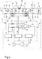
- Figure 4 shows an electrical circuit of a second alternative embodiment of the monitoring device of the invention which allows, in addition to monitoring the connection between the device 1 and the device 8, monitoring the connection between the source d supply 2 and device 1.
- the detection means comprise second means 58 for injecting the signal from the generator means 33.
- the second injection means 58 are formed by a transformer 60 whose primary 62 is connected between earth 42 and the output AT generator means 33 via a resistor 64 and the secondary 66 of which is connected in series between the third terminal 20 and the looping means 30.
- the primary 62 is also connected to a first input of an AND gate 68 whose second input is connected to the output of timer 47.
- the output of AND gate 68 is connected to the second input of an OR gate 70 whose first input is connected to the output of AND gate 48.
- the output of the OR gate 70 is finally connected to the input of the flip-flop 50.
- the loopback means 30 comprise, in addition to the capacitor 32, a second capacitor 72 connected in parallel between the first 18 and second 24 conductors of the connecting means and an inductor 74 arranged on the second conductor 24 between the first 32 and second 72 capacitors.
- These looping means have the advantage of preventing parasites from the power source arriving on the device to be monitored.
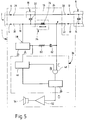
- the device 1 which has just been described may advantageously be in the form of a tap strip (not shown) in which the detection means 30, 33, 34, 36 comprise autonomous supply means (for example a battery) arranged in a housing comprising locking means with keys or the like.
- autonomous supply means for example a battery
Landscapes
- Physics & Mathematics (AREA)
- General Physics & Mathematics (AREA)
- Burglar Alarm Systems (AREA)
Applications Claiming Priority (4)
| Application Number | Priority Date | Filing Date | Title |
|---|---|---|---|
| CH235892 | 1992-07-27 | ||
| CH2358/92 | 1992-07-27 | ||
| FR9209754A FR2694636B1 (fr) | 1992-08-04 | 1992-08-04 | Dispositif de surveillance de la connexion d'un appareil électrique avec une source d'alimentation. |
| FR9209754 | 1992-08-04 |
Publications (1)
| Publication Number | Publication Date |
|---|---|
| EP0584540A1 true EP0584540A1 (de) | 1994-03-02 |
Family
ID=25690252
Family Applications (1)
| Application Number | Title | Priority Date | Filing Date |
|---|---|---|---|
| EP93111820A Ceased EP0584540A1 (de) | 1992-07-27 | 1993-07-23 | Einrichtung zur Überwachung der Verbindung eines elektrischen Apparates mit einer Versorgungsquelle |
Country Status (1)
| Country | Link |
|---|---|
| EP (1) | EP0584540A1 (de) |
Cited By (1)
| Publication number | Priority date | Publication date | Assignee | Title |
|---|---|---|---|---|
| US8466789B2 (en) | 2007-08-29 | 2013-06-18 | Fronius International Gmbh | Method for theft recognition on a photovoltaic unit and inverter for a photovoltaic unit |
Citations (10)
| Publication number | Priority date | Publication date | Assignee | Title |
|---|---|---|---|---|
| US4121201A (en) * | 1974-03-22 | 1978-10-17 | Bunker Ramo Corporation | Carrier current appliance theft alarm |
| GB2013904A (en) * | 1978-02-03 | 1979-08-15 | Midland Ross Corp | Fault monitoring and indicator system |
| DE3221176A1 (de) * | 1981-06-09 | 1982-12-23 | Schrack Elektronik-AG, 1121 Wien | Schaltungsanordnung zur ueberwachung von unterbrechungsstellen elektrischer bauteile |
| GB2172132A (en) * | 1985-02-22 | 1986-09-10 | Dme Ltd | Power line continuity monitoring circuit |
| US4736195A (en) * | 1987-02-24 | 1988-04-05 | Associates West, Inc. | Method and apparatus for warning of disconnection of an appliance from a power source |
| GB2195846A (en) * | 1986-10-09 | 1988-04-13 | Lucas Ind Plc | Detecting disconnection of electrical apparatus |
| EP0324318A1 (de) * | 1988-01-05 | 1989-07-19 | Transec Financiere S.A. | Einrichtung zum Überwachen ob ein Gerät oder eine Schaltung mit einem Stromnetz verbunden ist |
| GB2215106A (en) * | 1988-02-09 | 1989-09-13 | Dynamic Protection Limited | Monitoring of electrical connections |
| EP0357482A2 (de) * | 1988-08-04 | 1990-03-07 | France Telecom | Anordnung um ein elektrisches Gerät vor Diebstahl zu schützen |
| US4973945A (en) * | 1989-10-10 | 1990-11-27 | St John Havelin D | Magnetically linked theft sensing system |
-
1993
- 1993-07-23 EP EP93111820A patent/EP0584540A1/de not_active Ceased
Patent Citations (10)
| Publication number | Priority date | Publication date | Assignee | Title |
|---|---|---|---|---|
| US4121201A (en) * | 1974-03-22 | 1978-10-17 | Bunker Ramo Corporation | Carrier current appliance theft alarm |
| GB2013904A (en) * | 1978-02-03 | 1979-08-15 | Midland Ross Corp | Fault monitoring and indicator system |
| DE3221176A1 (de) * | 1981-06-09 | 1982-12-23 | Schrack Elektronik-AG, 1121 Wien | Schaltungsanordnung zur ueberwachung von unterbrechungsstellen elektrischer bauteile |
| GB2172132A (en) * | 1985-02-22 | 1986-09-10 | Dme Ltd | Power line continuity monitoring circuit |
| GB2195846A (en) * | 1986-10-09 | 1988-04-13 | Lucas Ind Plc | Detecting disconnection of electrical apparatus |
| US4736195A (en) * | 1987-02-24 | 1988-04-05 | Associates West, Inc. | Method and apparatus for warning of disconnection of an appliance from a power source |
| EP0324318A1 (de) * | 1988-01-05 | 1989-07-19 | Transec Financiere S.A. | Einrichtung zum Überwachen ob ein Gerät oder eine Schaltung mit einem Stromnetz verbunden ist |
| GB2215106A (en) * | 1988-02-09 | 1989-09-13 | Dynamic Protection Limited | Monitoring of electrical connections |
| EP0357482A2 (de) * | 1988-08-04 | 1990-03-07 | France Telecom | Anordnung um ein elektrisches Gerät vor Diebstahl zu schützen |
| US4973945A (en) * | 1989-10-10 | 1990-11-27 | St John Havelin D | Magnetically linked theft sensing system |
Cited By (2)
| Publication number | Priority date | Publication date | Assignee | Title |
|---|---|---|---|---|
| US8466789B2 (en) | 2007-08-29 | 2013-06-18 | Fronius International Gmbh | Method for theft recognition on a photovoltaic unit and inverter for a photovoltaic unit |
| EP2183730B1 (de) * | 2007-08-29 | 2013-07-24 | Fronius International GmbH | Verfahren zur diebstahlerkennung bei einer photovoltaikanlage und wechselrichter für eine photovoltaikanlage |
Similar Documents
| Publication | Publication Date | Title |
|---|---|---|
| EP1100226A1 (de) | Verfahren zur Fernspeisung eines Endgerätes in einem lokalen Netz | |
| FR2585158A1 (fr) | Systeme de surveillance de conditions dangereuses | |
| CA2763011A1 (fr) | Transmission bidirectionnelle sans fil de signaux de donnees serie entre un dispositif electronique et un compteur d'energie | |
| FR2701105A1 (fr) | Dispositif de déminage. | |
| EP0148674A1 (de) | Einrichtung und Verfahren zur Kabelfehlerortung | |
| FR2511511A1 (fr) | Systeme de localisation de boucles et d'ouvertures dans une ligne bifilaire | |
| EP0356334B1 (de) | System zur gegenseitigen Informationsübertragung zwischen einem tragbaren Gegenstand, insbesondere einem Schlüssel, und einem anderen Datenträger | |
| EP0815527B1 (de) | Koppler zur kommunikationsverwaltung zwischen einem tragbaren träger und einer datenaustauschvorrichtung und datenaustauschvorrichtung dafür | |
| EP0524300A1 (de) | Vorrichtung zum schutz von elektrischen geräten, maschinen und anlagen | |
| EP0584540A1 (de) | Einrichtung zur Überwachung der Verbindung eines elektrischen Apparates mit einer Versorgungsquelle | |
| EP0252801A1 (de) | Detektionsvorrichtung für einen elektromagnetischen Impuls, insbesondere hervorgerufen durch eine Kernexplosion | |
| CA1261410A (fr) | Dispositif pour controler la periode separant des impulsions | |
| FR2694636A1 (fr) | Dispositif de surveillance de la connexion d'un appareil électrique avec une source d'alimentation. | |
| EP0509920B1 (de) | Positionsmeldevorrichtung eines beweglichen Gliedes | |
| EP0110481A1 (de) | System zur Identifizierung lokaler Stationen durch eine zentrale Abfragestation | |
| EP0966800A1 (de) | Steuervorrichtung für trägerstromübertragung auf einem niedervoltnetz | |
| EP0866326B1 (de) | Installation zur Aufspürung und Ortung von Flüssigkeitsleckagen | |
| FR2654239A1 (fr) | Procede pour la protection d'un site interdit contre des intrusions et systeme pour la mise en óoeuvre de ce procede. | |
| WO2005029832A1 (fr) | Systeme et dispositif d'alimentation a distance d'un equipement de traitement d'informations | |
| FR2476878A1 (fr) | Detecteur a effet doppler | |
| EP0124422A1 (de) | Anordnung zum Abtrennen von Synchronimpulsen aus einem Fernsehsignal und zur Erzeugung von Klemmsignalen | |
| CA1092677A (fr) | Bloc d'alarme | |
| EP2166363B1 (de) | Multistandard-Anschlussvorrichtung | |
| EP0156727B1 (de) | Einrichtung zur Überwachung einer elektrischen Spannung, die ungewollten, momentanen Unterbrechungen unterworfen ist | |
| BE1005974A6 (fr) | Systeme d'alarme. |
Legal Events
| Date | Code | Title | Description |
|---|---|---|---|
| PUAI | Public reference made under article 153(3) epc to a published international application that has entered the european phase |
Free format text: ORIGINAL CODE: 0009012 |
|
| AK | Designated contracting states |
Kind code of ref document: A1 Designated state(s): CH DE FR GB LI |
|
| 17P | Request for examination filed |
Effective date: 19940819 |
|
| GRAG | Despatch of communication of intention to grant |
Free format text: ORIGINAL CODE: EPIDOS AGRA |
|
| 17Q | First examination report despatched |
Effective date: 19971023 |
|
| STAA | Information on the status of an ep patent application or granted ep patent |
Free format text: STATUS: THE APPLICATION HAS BEEN REFUSED |
|
| 18R | Application refused |
Effective date: 19980411 |