EP0585190A1 - Vorrichtung zur Reduktion von Eisenerzen in einer Zirkulierenden Schwebeschicht - Google Patents
Vorrichtung zur Reduktion von Eisenerzen in einer Zirkulierenden Schwebeschicht Download PDFInfo
- Publication number
- EP0585190A1 EP0585190A1 EP93470018A EP93470018A EP0585190A1 EP 0585190 A1 EP0585190 A1 EP 0585190A1 EP 93470018 A EP93470018 A EP 93470018A EP 93470018 A EP93470018 A EP 93470018A EP 0585190 A1 EP0585190 A1 EP 0585190A1
- Authority
- EP
- European Patent Office
- Prior art keywords
- gasifier
- reactor
- particles
- pipe
- gases
- Prior art date
- Legal status (The legal status is an assumption and is not a legal conclusion. Google has not performed a legal analysis and makes no representation as to the accuracy of the status listed.)
- Granted
Links
- XEEYBQQBJWHFJM-UHFFFAOYSA-N Iron Chemical compound [Fe] XEEYBQQBJWHFJM-UHFFFAOYSA-N 0.000 title claims abstract description 46
- 230000009467 reduction Effects 0.000 title claims abstract description 37
- 229910052742 iron Inorganic materials 0.000 title claims abstract description 23
- 239000007789 gas Substances 0.000 claims abstract description 64
- 239000002245 particle Substances 0.000 claims abstract description 56
- 238000000926 separation method Methods 0.000 claims abstract description 19
- 239000001257 hydrogen Substances 0.000 claims abstract description 17
- 229910052739 hydrogen Inorganic materials 0.000 claims abstract description 17
- UFHFLCQGNIYNRP-UHFFFAOYSA-N Hydrogen Chemical compound [H][H] UFHFLCQGNIYNRP-UHFFFAOYSA-N 0.000 claims abstract description 15
- QVGXLLKOCUKJST-UHFFFAOYSA-N atomic oxygen Chemical compound [O] QVGXLLKOCUKJST-UHFFFAOYSA-N 0.000 claims abstract description 11
- 239000001301 oxygen Substances 0.000 claims abstract description 11
- 229910052760 oxygen Inorganic materials 0.000 claims abstract description 11
- 238000002309 gasification Methods 0.000 claims abstract description 7
- 239000004215 Carbon black (E152) Substances 0.000 claims abstract description 3
- 229930195733 hydrocarbon Natural products 0.000 claims abstract description 3
- 150000002430 hydrocarbons Chemical class 0.000 claims abstract description 3
- 238000009434 installation Methods 0.000 claims description 24
- 239000000571 coke Substances 0.000 claims description 17
- 239000000463 material Substances 0.000 claims description 5
- XLYOFNOQVPJJNP-UHFFFAOYSA-N water Chemical compound O XLYOFNOQVPJJNP-UHFFFAOYSA-N 0.000 claims description 5
- 150000002431 hydrogen Chemical class 0.000 claims 2
- 238000006243 chemical reaction Methods 0.000 abstract description 6
- 238000006722 reduction reaction Methods 0.000 description 27
- 239000007787 solid Substances 0.000 description 24
- 239000003575 carbonaceous material Substances 0.000 description 7
- 238000005243 fluidization Methods 0.000 description 7
- 238000000034 method Methods 0.000 description 7
- 230000008569 process Effects 0.000 description 7
- 239000000203 mixture Substances 0.000 description 6
- 239000003245 coal Substances 0.000 description 5
- 230000004927 fusion Effects 0.000 description 3
- OKTJSMMVPCPJKN-UHFFFAOYSA-N Carbon Chemical compound [C] OKTJSMMVPCPJKN-UHFFFAOYSA-N 0.000 description 2
- 238000003723 Smelting Methods 0.000 description 2
- 229910052799 carbon Inorganic materials 0.000 description 2
- 238000002347 injection Methods 0.000 description 2
- 239000007924 injection Substances 0.000 description 2
- 239000007788 liquid Substances 0.000 description 2
- 238000011144 upstream manufacturing Methods 0.000 description 2
- 229910001018 Cast iron Inorganic materials 0.000 description 1
- 241000861223 Issus Species 0.000 description 1
- 229910000831 Steel Inorganic materials 0.000 description 1
- 230000009471 action Effects 0.000 description 1
- 238000005054 agglomeration Methods 0.000 description 1
- 230000002776 aggregation Effects 0.000 description 1
- 238000012550 audit Methods 0.000 description 1
- 230000008901 benefit Effects 0.000 description 1
- 230000015572 biosynthetic process Effects 0.000 description 1
- -1 coal Chemical compound 0.000 description 1
- 238000004939 coking Methods 0.000 description 1
- 238000010276 construction Methods 0.000 description 1
- 238000013461 design Methods 0.000 description 1
- 230000000694 effects Effects 0.000 description 1
- 238000005516 engineering process Methods 0.000 description 1
- 238000000605 extraction Methods 0.000 description 1
- 239000012530 fluid Substances 0.000 description 1
- 230000009931 harmful effect Effects 0.000 description 1
- 238000004519 manufacturing process Methods 0.000 description 1
- 239000002184 metal Substances 0.000 description 1
- 229910052751 metal Inorganic materials 0.000 description 1
- 238000012986 modification Methods 0.000 description 1
- 230000004048 modification Effects 0.000 description 1
- 230000003647 oxidation Effects 0.000 description 1
- 238000007254 oxidation reaction Methods 0.000 description 1
- JTJMJGYZQZDUJJ-UHFFFAOYSA-N phencyclidine Chemical class C1CCCCN1C1(C=2C=CC=CC=2)CCCCC1 JTJMJGYZQZDUJJ-UHFFFAOYSA-N 0.000 description 1
- 239000012429 reaction media Substances 0.000 description 1
- 238000010405 reoxidation reaction Methods 0.000 description 1
- 238000011160 research Methods 0.000 description 1
- 239000011343 solid material Substances 0.000 description 1
- 239000010959 steel Substances 0.000 description 1
- 230000009466 transformation Effects 0.000 description 1
Images

Classifications
-
- C—CHEMISTRY; METALLURGY
- C21—METALLURGY OF IRON
- C21B—MANUFACTURE OF IRON OR STEEL
- C21B13/00—Making spongy iron or liquid steel, by direct processes
- C21B13/0033—In fluidised bed furnaces or apparatus containing a dispersion of the material
-
- Y—GENERAL TAGGING OF NEW TECHNOLOGICAL DEVELOPMENTS; GENERAL TAGGING OF CROSS-SECTIONAL TECHNOLOGIES SPANNING OVER SEVERAL SECTIONS OF THE IPC; TECHNICAL SUBJECTS COVERED BY FORMER USPC CROSS-REFERENCE ART COLLECTIONS [XRACs] AND DIGESTS
- Y02—TECHNOLOGIES OR APPLICATIONS FOR MITIGATION OR ADAPTATION AGAINST CLIMATE CHANGE
- Y02P—CLIMATE CHANGE MITIGATION TECHNOLOGIES IN THE PRODUCTION OR PROCESSING OF GOODS
- Y02P10/00—Technologies related to metal processing
- Y02P10/10—Reduction of greenhouse gas [GHG] emissions
- Y02P10/122—Reduction of greenhouse gas [GHG] emissions by capturing or storing CO2
-
- Y—GENERAL TAGGING OF NEW TECHNOLOGICAL DEVELOPMENTS; GENERAL TAGGING OF CROSS-SECTIONAL TECHNOLOGIES SPANNING OVER SEVERAL SECTIONS OF THE IPC; TECHNICAL SUBJECTS COVERED BY FORMER USPC CROSS-REFERENCE ART COLLECTIONS [XRACs] AND DIGESTS
- Y02—TECHNOLOGIES OR APPLICATIONS FOR MITIGATION OR ADAPTATION AGAINST CLIMATE CHANGE
- Y02P—CLIMATE CHANGE MITIGATION TECHNOLOGIES IN THE PRODUCTION OR PROCESSING OF GOODS
- Y02P10/00—Technologies related to metal processing
- Y02P10/10—Reduction of greenhouse gas [GHG] emissions
- Y02P10/134—Reduction of greenhouse gas [GHG] emissions by avoiding CO2, e.g. using hydrogen
Definitions
- the invention relates to the field of reduction of iron ore in installations operating with a fluidized bed of ore.
- fusion reduction or “smelting reduction” processes.
- a family of these processes combines two reactors. One of these reactors produces very strongly reduced metal ore from iron ore, which is placed in the second reactor to be transformed into liquid iron. The gas circuits of these two reactors can be linked to each other, or be completely independent.
- the gases then escape from the reactor, while the particles descend into a gasifier, where excess carbon and oxygen are introduced in order to form CO and hydrogen which will contribute to the reduction of the ore.
- the excess coal is transformed into semi-coke.
- the solids and gases then return to the pre-reduction reactor.
- New ore is introduced into the material stream, preferably between the cyclone and the gasifier.
- the gases which have escaped from the cyclone are purified and reintroduced at the base of the prereduction reactor and also possibly at the base of the gasifier, where they can replay their role of fluidizing and reaction medium.
- the gas from the gasifier has already started to reduce the iron ore which it contributes to transport, in particular the new ore introduced between the cyclone and the gasifier. It is therefore a gas which is already considerably oxidized and which enters the upper part of the prereduction reactor, where it mixes with the gases which have continued to reduce the ore in the lower part of this same reactor.
- This oxidized gas can therefore hardly help to complete the reduction of the ore in the upper part of the reactor, and can even reduce the efficiency of this reaction if its degree of oxidation is higher than that of the gases from the lower part.
- This harmful effect can be further aggravated if the partial gasification of coal delivers a relatively oxidized gas which does not produce metallic iron.
- the object of the invention is to guarantee regular and efficient operation of the prereduction reactor over its entire height while simplifying its design.
- the invention consists in separating the solid particles (ore being reduced, metallic iron and semi-coke) and the reducing gases already partially oxidized, at the end of their passage through the gasifier.
- the solid particles are sent into the pre-reduction reactor, while the gases are reinjected into the installation downstream of the pre-reduction reactor and upstream of the gas-particle separation means.
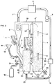
- FIG. 1 shows an iron ore reduction plant consisting essentially of three parts.
- a pre-reduction reactor 1 contains at its base a bed 2 of relatively dense solid particles, essentially containing iron ore, most of which is in a reduced state, mixed with semi-coke.
- This bed 2 rests on a support 3 permeable to gases.
- the bed 2 is crossed by a gaseous fluidization current which puts it into circulation through the installation, as indicated by the arrows 4, 4 ', 4''.
- This fluidizing gas is a reducing gas, namely a CO / CO2 / H2 / H20 mixture which is injected at the base of the reactor 1 through a pipe 5. It moves at a speed of the order of 2 to 10 m / s.
- the iron ore particles initially oxidized in their natural state undergo reduction to metallic iron by CO and hydrogen from the fluidization gases.
- the gases and the solid particles escape from the prereduction reactor 1 via a pipe 30 and then enter a cyclone 6, in which they are separated from each other.
- the gases are evacuated from the cyclone via a pipe 7, while the solid particles fall back into the lower part of the cyclone 6.
- the gases are purified from the CO2 and the water vapor which they contain in a suitable reactor 8 of a type known in itself, are returned by suitable means symbolized by the pump 9 and the line 10 to the base of the reactor 1, after having passed through a preheater 36, and are again used for fluidization and reduction of the ore.
- the solid particles leaving cyclone 6 are brought via a pipe 11 to a gasification or gasifier reactor 12. On this pipe 11 is connected a hopper 13 containing new ore to be reduced, the admission of which into the installation is controlled by the valve 14.
- the gasifier 12 has the function of generating the gas used for the fluidization and the circulation of the particles, and of supplying the energy necessary for the equilibrium of the thermal balance. To this end, injections of oxygen and carbonaceous materials, such as coal, are carried out there, these carbonaceous materials being in excess. CO and hydrogen are thus formed (with a certain proportion of CO2 and water vapor) which will react with the ore to reduce it to iron and oxidize themselves to CO2 and water vapor, while the excess coal turns into semi-coke.
- the gas temperature is around 950 ° C, and the proportion of CO2 and water vapor they contain is around 30 to 40%.
- the carbonaceous materials 15 contained in a hopper 16 are introduced into the gasifier 12 by a line 17, and their admission is controlled by a valve 18.
- the oxygen, contained in a tank 19, is likewise blown into the gasifier 2 by a pipe 20, and its admission is controlled by a valve 21.
- the CO is created by reaction of carbonaceous materials with oxygen inside the gasifier 12. It is also possible, as proposed in the application FR 91 14467 already mentioned, form CO and hydrogen in a burner upstream of which the lines 17 and 20 meet, therefore before the carbonaceous materials and oxygen enter the gasifier 12. This latter configuration makes it possible to avoid reoxidation in the gasifier 12 of iron particles in contact with oxygen not yet combined with carbon.
- the introduction into the gasifier 12 of the various solid particles and the formation of gases has the effect that in the lower part of the gasifier 12 a bed is formed fluidized 22 of solid particles which is maintained in a relatively dense state.
- the fluidization of the particles is also ensured by gases coming from a pipe 23, derived from the pipe 10, and opening into the bottom of the gasifier 12.
- a grid 24 permeable to gases then retains the lower part of this bed 22.
- This bed 22 of solid particles comprises ore being reduced, a fraction of metallic iron corresponding to the ore already reduced and semi-coke. They arise from the reactions between the ore, the carbonaceous materials, the oxygen introduced and the gases resulting from the reactions between the carbonaceous materials and the oxygen, then between the solid particles and the gases (CO, CO2, H2, H20) .
- the operating parameters of the gasifier 12 are calculated in such a way that the "free surface" 25 of the fluidized bed 22 arrives at least at the level of a pipe 26 which makes the gasifier 12 communicate with the lower part of the prereduction reactor 1.
- solid particles 22 pass from the gasifier 12 to the prereduction reactor 1, which ensures a permanent circulation of solid particles inside the entire installation.
- the gases formed in the gasifier 12 and those possibly injected at its base escape from the gasifier 12 via a pipe 27. This starts from the top of the gasifier 12 and arrives in the particle circulation circuit, in a point located on line 30, ie between the prereduction reactor 1 and the cyclone 6. These gases carry with them only a residual quantity of solid particles.
- the solid particles produced by the installation ie ore reduced to at least 75% and semi-coke, are collected at the base of the pre-reduction reactor 1 by a line 28, fitted with a valve 29. They are then ready to be introduced into a fusion reactor, where liquid iron will be produced.
- the advantage of this configuration compared to the conventional configuration, where solid particles and gases pass together from the gasifier to the reactor pre-reduction, is that the gases already passably oxidized leaving the gasifier 12 will not mix with the gases circulating in the pre-reduction reactor 1. These are generally less oxidized than the gases from the gasifier 12, and can thus continue the reaction reduction of the ore up to the upper part of the prereduction reactor, without fear of seeing their reducing possibilities degraded by the gases coming from the gasifier 12.
- the flow rate of the gases transported being constant over the entire height of the prereduction reactor , it is possible to give it a substantially cylindrical shape while maintaining a constant gas velocity.
- FIG. 2 shows another variant of the invention, in which the solid particles passing through the gasifier 12 are no longer formed in the form of a dense fluidized bed, but of a circulating fluidized bed 30.
- a pipe 31 brings these solid particles and the gases which transport them into a second cyclone 32 which ensures their separation.
- a pipe 33 brings the solid particles collected at the base of said second cyclone 32 into the gasifier 12.
- a pipe 34 connects the upper part of the second cyclone 32 to the pipe 30 connecting the prereduction reactor 1 to the first cyclone 6. It fulfills the same function as the pipe 27 of FIG.
- a pipe 35 transfers the solid particles from the gasifier 12 into the prereduction reactor 1 (the members of the variant shown in FIG. 1 which are found in the variant of FIG. 2 are referenced therein by the same references).
- the supply of gases containing CO and hydrogen to the base of the prereduction reactor 1 and of the gasification reactor 12 can have other origins than the gases escaping from the cyclone 6. They can, for example, come from a reactor ensuring the fusion and the complete reduction of the reduced ore and its transformation into cast iron.
- the addition of new ore to the particles circulating in the installation can be carried out at any suitable location, and not necessarily between the first cyclone and the gasifier.
- the cyclones can be replaced by any other suitable means of separation of gases and particles.
Landscapes
- Chemical & Material Sciences (AREA)
- Engineering & Computer Science (AREA)
- Dispersion Chemistry (AREA)
- Manufacturing & Machinery (AREA)
- Materials Engineering (AREA)
- Metallurgy (AREA)
- Organic Chemistry (AREA)
- Manufacture Of Iron (AREA)
- Manufacture And Refinement Of Metals (AREA)
- Crucibles And Fluidized-Bed Furnaces (AREA)
- Devices And Processes Conducted In The Presence Of Fluids And Solid Particles (AREA)
Applications Claiming Priority (2)
| Application Number | Priority Date | Filing Date | Title |
|---|---|---|---|
| FR9210340 | 1992-08-25 | ||
| FR9210340A FR2695141B1 (fr) | 1992-08-25 | 1992-08-25 | Installation de réduction du minerai de fer utilisant un lit fluidisé circulant. |
Publications (2)
| Publication Number | Publication Date |
|---|---|
| EP0585190A1 true EP0585190A1 (de) | 1994-03-02 |
| EP0585190B1 EP0585190B1 (de) | 1998-09-23 |
Family
ID=9433059
Family Applications (1)
| Application Number | Title | Priority Date | Filing Date |
|---|---|---|---|
| EP93470018A Expired - Lifetime EP0585190B1 (de) | 1992-08-25 | 1993-08-17 | Vorrichtung zur Reduktion von Eisenerzen in einer Zirkulierenden Schwebeschicht |
Country Status (5)
| Country | Link |
|---|---|
| EP (1) | EP0585190B1 (de) |
| AT (1) | ATE171482T1 (de) |
| DE (1) | DE69321180T2 (de) |
| ES (1) | ES2121972T3 (de) |
| FR (1) | FR2695141B1 (de) |
Cited By (2)
| Publication number | Priority date | Publication date | Assignee | Title |
|---|---|---|---|---|
| WO2000037687A1 (en) * | 1998-12-22 | 2000-06-29 | Pohang Iron & Steel Co., Ltd. | Complex fluidized bed type fine iron ore reducing apparatus, and method therefor |
| RU2195501C1 (ru) * | 1999-12-20 | 2002-12-27 | Похэнг Айэн Энд Стил Ко., Лтд. | Реактор с кипящим слоем, предотвращающий налипание измельченной железной руды, и предназначенный для этого способ |
Citations (4)
| Publication number | Priority date | Publication date | Assignee | Title |
|---|---|---|---|---|
| FR1461798A (fr) * | 1964-12-07 | 1966-12-09 | Pullman Inc | Procédé destiné à produire une réaction entre des gaz et des matières solides |
| US4084958A (en) * | 1974-05-20 | 1978-04-18 | Stora Kopparbergs Bergslags Aktiebolag | Method of reducing finely grained material containing iron oxides in a fluid bed |
| JPS57188607A (en) * | 1981-05-14 | 1982-11-19 | Kawasaki Steel Corp | Fluidized-bed reducing method for iron ore for manufacturing reduced iron and fuel gas simultaneously |
| EP0255180A1 (de) * | 1986-08-01 | 1988-02-03 | Metallgesellschaft Ag | Verfahren zur Reduktion feinkörniger, eisenhaltiger Materialien mit festen kohlenstoffhaltigen Reduktionsmitteln |
-
1992
- 1992-08-25 FR FR9210340A patent/FR2695141B1/fr not_active Expired - Fee Related
-
1993
- 1993-08-17 EP EP93470018A patent/EP0585190B1/de not_active Expired - Lifetime
- 1993-08-17 AT AT93470018T patent/ATE171482T1/de not_active IP Right Cessation
- 1993-08-17 ES ES93470018T patent/ES2121972T3/es not_active Expired - Lifetime
- 1993-08-17 DE DE69321180T patent/DE69321180T2/de not_active Expired - Fee Related
Patent Citations (4)
| Publication number | Priority date | Publication date | Assignee | Title |
|---|---|---|---|---|
| FR1461798A (fr) * | 1964-12-07 | 1966-12-09 | Pullman Inc | Procédé destiné à produire une réaction entre des gaz et des matières solides |
| US4084958A (en) * | 1974-05-20 | 1978-04-18 | Stora Kopparbergs Bergslags Aktiebolag | Method of reducing finely grained material containing iron oxides in a fluid bed |
| JPS57188607A (en) * | 1981-05-14 | 1982-11-19 | Kawasaki Steel Corp | Fluidized-bed reducing method for iron ore for manufacturing reduced iron and fuel gas simultaneously |
| EP0255180A1 (de) * | 1986-08-01 | 1988-02-03 | Metallgesellschaft Ag | Verfahren zur Reduktion feinkörniger, eisenhaltiger Materialien mit festen kohlenstoffhaltigen Reduktionsmitteln |
Non-Patent Citations (1)
| Title |
|---|
| PATENT ABSTRACTS OF JAPAN vol. 7, no. 34 (C - 150)<1179> 10 February 1983 (1983-02-10) * |
Cited By (2)
| Publication number | Priority date | Publication date | Assignee | Title |
|---|---|---|---|---|
| WO2000037687A1 (en) * | 1998-12-22 | 2000-06-29 | Pohang Iron & Steel Co., Ltd. | Complex fluidized bed type fine iron ore reducing apparatus, and method therefor |
| RU2195501C1 (ru) * | 1999-12-20 | 2002-12-27 | Похэнг Айэн Энд Стил Ко., Лтд. | Реактор с кипящим слоем, предотвращающий налипание измельченной железной руды, и предназначенный для этого способ |
Also Published As
| Publication number | Publication date |
|---|---|
| ES2121972T3 (es) | 1998-12-16 |
| ATE171482T1 (de) | 1998-10-15 |
| DE69321180T2 (de) | 1999-05-20 |
| DE69321180D1 (de) | 1998-10-29 |
| EP0585190B1 (de) | 1998-09-23 |
| FR2695141B1 (fr) | 1994-10-07 |
| FR2695141A1 (fr) | 1994-03-04 |
Similar Documents
| Publication | Publication Date | Title |
|---|---|---|
| EP0173782B1 (de) | Verfahren zur Behandlung von Materialen | |
| CA2799133C (fr) | Procede de combustion en boucle chimique avec une zone de reaction integrant une zone de separation gaz-solide et installation utilisant un tel procede | |
| EP2758711B1 (de) | Chemical-looping-combustion mit entfernung von asche und feinstoffen im reduktionsbereich und anlage zur durchführung des verfahrens | |
| EP2454525B1 (de) | Verfahren für chemical-looping-combustion mit unabhängiger steuerung der feststoffzirkulation | |
| CA2850612C (fr) | Procede de combustion en boucle chimique avec elimination des cendres et fines en sortie de la zone d'oxydation et installation utilisant un tel procede | |
| EP0161970A1 (de) | Verfahren und Anlage zur Materialbehandlung in einer zirkulierenden Wirbelschicht | |
| WO2007074304A1 (fr) | Installation de conversion d'hydrocarbures petroliers a installation de combustion integree comprenant une capture du dioxyde de carbone | |
| KR20230135096A (ko) | 철광석을 직접 환원 샤프트에 장입하고/하거나 직접환원 샤프트에서 해면철을 배출하기 위한 장치 및 방법 | |
| EP0585190B1 (de) | Vorrichtung zur Reduktion von Eisenerzen in einer Zirkulierenden Schwebeschicht | |
| WO2010076499A2 (fr) | Procede et dispositif de production et de purification de gaz de synthese | |
| EP0543758B1 (de) | Vorrichtung zum Reduzieren eisenoxydhaltiger Materialien in einer zirkulierenden Wirbelschicht | |
| EP0543757B1 (de) | Anlage zur Eisenerzreduktion in circulierenden Wirbelschicht | |
| EP0617136A1 (de) | Anlage zum Reduzieren von Eisenerzen mit einer Feststoffdurchflussmengenreguliervorrichtung versehenen zirkulierenden Wirbelschicht | |
| EP0626547B1 (de) | Verfahren zur Herstellung von geschmolzenem Stahl aus Kohlenstoffenreichem eisenhaltigen Material | |
| EP0599760B1 (de) | Anlage zum Reduzieren von Eisenerzen in einer durch Reduktionsgase aufgewirbelten Schicht aus festen Teilchen | |
| FR2691718A1 (fr) | Procédé de séparation de matières ferreuses et carbonées à la sortie d'une installation de réduction du minerai de fer, et dispositif pour sa mise en Óoeuvre. | |
| FR2556001A1 (fr) | Procede et installation pour reduire une matiere oxydee | |
| EP1235889A1 (de) | Verfahren und anlage zur vergasung von kohlenstoffhaltigen materialien | |
| FR3156800A1 (fr) | Système de gazeification | |
| FR2556002A1 (fr) | Procede et installation pour la reduction de matiere oxydees, avec generation simultanee d'un gaz approprie comme gaz combustible | |
| WO2025104405A1 (fr) | Captation d'un composant polluant concentré provenant d'une cuve d'électrolyse pour la production d'aluminium | |
| WO2020058141A1 (fr) | Dispositif et procede de combustion en boucle chimique avec separateur de particules muni d'une conduite d'admission inclinee | |
| FR2528162A1 (fr) | Four a arc de production d'un gaz reducteur | |
| BE843776A (fr) | Procede pour la production d'un produit partiellement reduit et produit obtenu par ce procede |
Legal Events
| Date | Code | Title | Description |
|---|---|---|---|
| PUAI | Public reference made under article 153(3) epc to a published international application that has entered the european phase |
Free format text: ORIGINAL CODE: 0009012 |
|
| AK | Designated contracting states |
Kind code of ref document: A1 Designated state(s): AT BE DE ES GB IT NL SE |
|
| 17P | Request for examination filed |
Effective date: 19940705 |
|
| 17Q | First examination report despatched |
Effective date: 19970505 |
|
| GRAG | Despatch of communication of intention to grant |
Free format text: ORIGINAL CODE: EPIDOS AGRA |
|
| GRAG | Despatch of communication of intention to grant |
Free format text: ORIGINAL CODE: EPIDOS AGRA |
|
| GRAH | Despatch of communication of intention to grant a patent |
Free format text: ORIGINAL CODE: EPIDOS IGRA |
|
| GRAH | Despatch of communication of intention to grant a patent |
Free format text: ORIGINAL CODE: EPIDOS IGRA |
|
| GRAA | (expected) grant |
Free format text: ORIGINAL CODE: 0009210 |
|
| AK | Designated contracting states |
Kind code of ref document: B1 Designated state(s): AT BE DE ES GB IT NL SE |
|
| REF | Corresponds to: |
Ref document number: 171482 Country of ref document: AT Date of ref document: 19981015 Kind code of ref document: T |
|
| REF | Corresponds to: |
Ref document number: 69321180 Country of ref document: DE Date of ref document: 19981029 |
|
| GBT | Gb: translation of ep patent filed (gb section 77(6)(a)/1977) |
Effective date: 19981124 |
|
| REG | Reference to a national code |
Ref country code: ES Ref legal event code: FG2A Ref document number: 2121972 Country of ref document: ES Kind code of ref document: T3 |
|
| PLBE | No opposition filed within time limit |
Free format text: ORIGINAL CODE: 0009261 |
|
| STAA | Information on the status of an ep patent application or granted ep patent |
Free format text: STATUS: NO OPPOSITION FILED WITHIN TIME LIMIT |
|
| 26N | No opposition filed | ||
| REG | Reference to a national code |
Ref country code: GB Ref legal event code: IF02 |
|
| PGFP | Annual fee paid to national office [announced via postgrant information from national office to epo] |
Ref country code: NL Payment date: 20030728 Year of fee payment: 11 Ref country code: GB Payment date: 20030728 Year of fee payment: 11 |
|
| PGFP | Annual fee paid to national office [announced via postgrant information from national office to epo] |
Ref country code: AT Payment date: 20030729 Year of fee payment: 11 |
|
| PGFP | Annual fee paid to national office [announced via postgrant information from national office to epo] |
Ref country code: BE Payment date: 20030731 Year of fee payment: 11 |
|
| PGFP | Annual fee paid to national office [announced via postgrant information from national office to epo] |
Ref country code: DE Payment date: 20030805 Year of fee payment: 11 |
|
| PGFP | Annual fee paid to national office [announced via postgrant information from national office to epo] |
Ref country code: ES Payment date: 20030807 Year of fee payment: 11 |
|
| PGFP | Annual fee paid to national office [announced via postgrant information from national office to epo] |
Ref country code: SE Payment date: 20030808 Year of fee payment: 11 |
|
| PG25 | Lapsed in a contracting state [announced via postgrant information from national office to epo] |
Ref country code: GB Free format text: LAPSE BECAUSE OF NON-PAYMENT OF DUE FEES Effective date: 20040817 Ref country code: AT Free format text: LAPSE BECAUSE OF NON-PAYMENT OF DUE FEES Effective date: 20040817 |
|
| PG25 | Lapsed in a contracting state [announced via postgrant information from national office to epo] |
Ref country code: SE Free format text: LAPSE BECAUSE OF NON-PAYMENT OF DUE FEES Effective date: 20040818 Ref country code: ES Free format text: LAPSE BECAUSE OF NON-PAYMENT OF DUE FEES Effective date: 20040818 |
|
| PG25 | Lapsed in a contracting state [announced via postgrant information from national office to epo] |
Ref country code: BE Free format text: LAPSE BECAUSE OF NON-PAYMENT OF DUE FEES Effective date: 20040831 |
|
| BERE | Be: lapsed |
Owner name: S.A. *SOLLAC Effective date: 20040831 |
|
| PG25 | Lapsed in a contracting state [announced via postgrant information from national office to epo] |
Ref country code: NL Free format text: LAPSE BECAUSE OF NON-PAYMENT OF DUE FEES Effective date: 20050301 Ref country code: DE Free format text: LAPSE BECAUSE OF NON-PAYMENT OF DUE FEES Effective date: 20050301 |
|
| EUG | Se: european patent has lapsed | ||
| GBPC | Gb: european patent ceased through non-payment of renewal fee |
Effective date: 20040817 |
|
| NLV4 | Nl: lapsed or anulled due to non-payment of the annual fee |
Effective date: 20050301 |
|
| PG25 | Lapsed in a contracting state [announced via postgrant information from national office to epo] |
Ref country code: IT Free format text: LAPSE BECAUSE OF NON-PAYMENT OF DUE FEES;WARNING: LAPSES OF ITALIAN PATENTS WITH EFFECTIVE DATE BEFORE 2007 MAY HAVE OCCURRED AT ANY TIME BEFORE 2007. THE CORRECT EFFECTIVE DATE MAY BE DIFFERENT FROM THE ONE RECORDED. Effective date: 20050817 |
|
| REG | Reference to a national code |
Ref country code: ES Ref legal event code: FD2A Effective date: 20040818 |
|
| BERE | Be: lapsed |
Owner name: S.A. *SOLLAC Effective date: 20040831 |