EP0585204A1 - Procédé et dispositif pour le revêtement d'objets en forme de plaques en particulier cartes de circuit imprimé - Google Patents
Procédé et dispositif pour le revêtement d'objets en forme de plaques en particulier cartes de circuit imprimé Download PDFInfo
- Publication number
- EP0585204A1 EP0585204A1 EP93810577A EP93810577A EP0585204A1 EP 0585204 A1 EP0585204 A1 EP 0585204A1 EP 93810577 A EP93810577 A EP 93810577A EP 93810577 A EP93810577 A EP 93810577A EP 0585204 A1 EP0585204 A1 EP 0585204A1
- Authority
- EP
- European Patent Office
- Prior art keywords
- circuit boards
- printed circuit
- station
- coating
- longitudinal edges
- Prior art date
- Legal status (The legal status is an assumption and is not a legal conclusion. Google has not performed a legal analysis and makes no representation as to the accuracy of the status listed.)
- Granted
Links
- 238000000576 coating method Methods 0.000 title claims abstract description 95
- 239000011248 coating agent Substances 0.000 title claims abstract description 94
- 238000000034 method Methods 0.000 title claims abstract description 21
- 238000001035 drying Methods 0.000 claims abstract description 58
- 238000012545 processing Methods 0.000 claims abstract description 26
- 239000000463 material Substances 0.000 claims abstract description 6
- 238000005266 casting Methods 0.000 claims description 10
- 238000012546 transfer Methods 0.000 claims description 8
- 238000003780 insertion Methods 0.000 claims description 6
- 230000037431 insertion Effects 0.000 claims description 6
- 239000004922 lacquer Substances 0.000 claims description 3
- 230000001419 dependent effect Effects 0.000 claims description 2
- 239000003973 paint Substances 0.000 claims 2
- 238000013022 venting Methods 0.000 abstract 2
- 239000002966 varnish Substances 0.000 abstract 1
- 239000011241 protective layer Substances 0.000 description 5
- 239000004020 conductor Substances 0.000 description 3
- 230000006378 damage Effects 0.000 description 3
- 238000010438 heat treatment Methods 0.000 description 3
- 208000027418 Wounds and injury Diseases 0.000 description 2
- 208000014674 injury Diseases 0.000 description 2
- 238000010276 construction Methods 0.000 description 1
- 238000013461 design Methods 0.000 description 1
- 239000002904 solvent Substances 0.000 description 1
Images






Classifications
-
- H—ELECTRICITY
- H05—ELECTRIC TECHNIQUES NOT OTHERWISE PROVIDED FOR
- H05K—PRINTED CIRCUITS; CASINGS OR CONSTRUCTIONAL DETAILS OF ELECTRIC APPARATUS; MANUFACTURE OF ASSEMBLAGES OF ELECTRICAL COMPONENTS
- H05K13/00—Apparatus or processes specially adapted for manufacturing or adjusting assemblages of electric components
- H05K13/0061—Tools for holding the circuit boards during processing; handling transport of printed circuit boards
-
- H—ELECTRICITY
- H05—ELECTRIC TECHNIQUES NOT OTHERWISE PROVIDED FOR
- H05K—PRINTED CIRCUITS; CASINGS OR CONSTRUCTIONAL DETAILS OF ELECTRIC APPARATUS; MANUFACTURE OF ASSEMBLAGES OF ELECTRICAL COMPONENTS
- H05K3/00—Apparatus or processes for manufacturing printed circuits
- H05K3/0091—Apparatus for coating printed circuits using liquid non-metallic coating compositions
-
- H—ELECTRICITY
- H05—ELECTRIC TECHNIQUES NOT OTHERWISE PROVIDED FOR
- H05K—PRINTED CIRCUITS; CASINGS OR CONSTRUCTIONAL DETAILS OF ELECTRIC APPARATUS; MANUFACTURE OF ASSEMBLAGES OF ELECTRICAL COMPONENTS
- H05K2203/00—Indexing scheme relating to apparatus or processes for manufacturing printed circuits covered by H05K3/00
- H05K2203/11—Treatments characterised by their effect, e.g. heating, cooling, roughening
- H05K2203/111—Preheating, e.g. before soldering
-
- H—ELECTRICITY
- H05—ELECTRIC TECHNIQUES NOT OTHERWISE PROVIDED FOR
- H05K—PRINTED CIRCUITS; CASINGS OR CONSTRUCTIONAL DETAILS OF ELECTRIC APPARATUS; MANUFACTURE OF ASSEMBLAGES OF ELECTRICAL COMPONENTS
- H05K2203/00—Indexing scheme relating to apparatus or processes for manufacturing printed circuits covered by H05K3/00
- H05K2203/15—Position of the PCB during processing
- H05K2203/1509—Horizontally held PCB
-
- H—ELECTRICITY
- H05—ELECTRIC TECHNIQUES NOT OTHERWISE PROVIDED FOR
- H05K—PRINTED CIRCUITS; CASINGS OR CONSTRUCTIONAL DETAILS OF ELECTRIC APPARATUS; MANUFACTURE OF ASSEMBLAGES OF ELECTRICAL COMPONENTS
- H05K2203/00—Indexing scheme relating to apparatus or processes for manufacturing printed circuits covered by H05K3/00
- H05K2203/15—Position of the PCB during processing
- H05K2203/159—Using gravitational force; Processing against the gravity direction; Using centrifugal force
-
- H—ELECTRICITY
- H05—ELECTRIC TECHNIQUES NOT OTHERWISE PROVIDED FOR
- H05K—PRINTED CIRCUITS; CASINGS OR CONSTRUCTIONAL DETAILS OF ELECTRIC APPARATUS; MANUFACTURE OF ASSEMBLAGES OF ELECTRICAL COMPONENTS
- H05K3/00—Apparatus or processes for manufacturing printed circuits
- H05K3/22—Secondary treatment of printed circuits
- H05K3/227—Drying of printed circuits
Definitions
- the invention relates to a method for coating plate-like material, in particular printed circuit boards, according to the preamble of claim 1. Furthermore, the invention also relates to a device suitable for this, according to the preamble of claim 12.
- Printed circuit boards are coated with a protective layer after they have been provided with conductor tracks.
- This protective layer is a preferably UV-curable, exposable plastic, lacquer or the like. After the protective layer has dried, it is exposed in a suitable form and developed at the exposed areas. The conductor tracks are then exposed at these points and can be electrically contacted.
- both surfaces of the boards must be coated without damaging the coating previously applied to the first side when coating the second side.
- the circuit boards have to be transported through a series of processing stations in a coating system. There, the previously cleaned printed circuit boards are first preheated and provided with the protective layer on one side.
- the circuit boards to be coated are preferably transported in a coating station under a free-falling pouring curtain. After the first side has been coated, the printed circuit boards are transported to an exhaust air and drying station, in which the solvent is evaporated (vented) and the coated surface of the printed circuit boards is dried. If the second side of the printed circuit boards is also to be coated, these are turned over, transported again under a pouring curtain from a fine coating station and finally vented and dried in an exhaust air and drying station.
- circuit boards When transporting the circuit boards from one processing station to the next, especially when transporting the boards with a wet coating and with circuit boards already coated on one side, care must be taken not to damage or injure the circuit board and the coating.
- the circuit boards are transported in the individual processing stations and from station to station with the aid of various automatic conveyors.
- the tendency to use ever thinner circuit board materials poses the problem that the circuit boards tend to bend during transport and in particular due to the heat treatment in the preheating station and in the exhaust and drying stations and with their underside on the conveyors or Means of transport to get in touch. This is particularly tricky when the circuit boards are to be coated on both sides and the soft protective layer on the underside of the circuit boards is damaged.
- the conveyors or means of transport can also become dirty.
- the proposed coating system requires a separate centering station, which aligns the circuit boards before they are transported under the casting curtain in the coating station.
- US-A-4,926,789 describes holding devices for printed circuit boards which comprise clamps which grip the printed circuit boards at several points on their longitudinal edges.
- the printed circuit boards together with the holding devices are transferred from one processing station to the next. Only starting In the coating system, the holding devices are detached from the plates and transported back to the input of the system.
- the system described is relatively complex in its construction and requires separate feed lifts, conveyor belts and transport means for the holding devices. Actuating devices for the holding clamps of the holding devices must also be provided at the entrance and exit of the coating system. In addition, there is a risk in the coating station that the holding devices become dirty during transport under the pouring curtain.
- US Pat. No. 4,848,533 describes a printed circuit board transport device which has two chains or the like which revolve parallel to one another.
- the chains are connected by means of crossbeams spaced apart from one another.
- Two brackets designed as clamps are braked and slidable against each other on each traverse.
- two pneumatically driven plungers push the passing brackets in pairs onto the longitudinal edges of the plate, where they clamp. In this way, at least two, but usually several pairs of brackets are clamped along the longitudinal edges of a printed circuit board, and these are held in this manner along the transport path.
- two further plungers are provided, which push the holders apart again, whereby the circuit boards are released again.
- the printed circuit boards are held at their longitudinal edges by at least two pairs of brackets, ensuring that the underside of the plates does not come into contact with the transport chains or with the traverses.
- the transport device is only designed for the horizontal transport of the printed circuit boards, for example under the pouring curtain.
- the holders In order to transfer the plates to the drying station, for example, the holders must first be removed again, and the plates reloaded onto a roller conveyor, for example, via which they can then be moved into the drying station holders.
- the device is structurally relatively complex.
- the many pairs of brackets that have to be movable against each other on the crossbars represent a possible source of error. For example, one or more crossbars could be contaminated, which can seriously impair the movability of the brackets, so that reliable gripping of the printed circuit boards is no longer guaranteed.
- the method is intended to allow a printed circuit board to be transported without injury through an exhaust air and drying station with vertically rotating support elements and to be turned.
- the circuit board should essentially always be guided and supported along its coating-free longitudinal edges.
- the interface between the coating station and the exhaust air and drying station should be free of roller conveyors or similar transport devices.
- the circuit boards should not be clamped or gripped on their long sides, but should still be guided.
- a circuit board coating system which is shown in FIGS. 1 to 3 in three exemplary embodiments, is denoted overall by 1 in each case.
- the three exemplary embodiments of the coating system according to the invention differ in the different degree of expansion, that is to say in the different number of processing stations for printed circuit boards 2 to be coated.
- the coating system 1 shown schematically in FIG. 1 comprises, in the order of its arrangement, a preheating station 6, a coating station 7 and an exhaust air and drying station 8, through which the printed circuit boards 2 pass one after the other in the direction of travel D.
- An input roller conveyor 12 and a transfer roller conveyor 14 are provided at the entrance and exit of the preheating station.
- An output roller conveyor 13 is arranged at the outlet of the exhaust air and drying station 8, via which the circuit boards 2 can be fed to further processing systems.
- the printed circuit boards are taken over by means of transport 17, 18 and 20 and transported through the respective station and transferred to the processing station following in the transport direction D of the printed circuit boards 2.
- the coating station 7 comprises a casting table 15 with a casting head.
- the casting head is designed such that preferably UV-curable plastic C, lacquer or the like, which is pumped to the casting head, forms a free-falling pouring curtain 16, under which the surfaces of the printed circuit boards 2 to be coated are transported.
- the lateral extent of the casting curtain 16, transverse to the transport direction D of the circuit boards 2, is limited by the casting knife.
- Such a pouring head is described, for example, in US-A-4,559,896, the content of which hereby declared to be an integral part of the present description.
- the casting knife ensures that a narrow edge along the long sides of the printed circuit boards 2 remains free of the coating C.
- the transport means 18 for the printed circuit boards 2 in the coating station 7 comprise lateral guide means 19 for the longitudinal edges of the printed circuit boards. These are preferably formed by two laterally arranged conveyor belts, each of which runs around an associated straightening bar in the transport direction D of the printed circuit boards 2.
- the directional bars can be adjusted automatically, preferably electro-pneumatically, to the width of the circuit boards. In this way, the printed circuit boards 2 are aligned so that their longitudinal edges run approximately parallel to the transport direction D.
- the conveyor belts grip the longitudinal edges of the printed circuit boards 2 and transport them for coating under the freely falling pouring curtain 16.
- the pouring knife that delimits the pouring curtain on the side ensures that the conveyor belts are not contaminated.
- the coating system 1 according to FIG. 1 is designed for coating only one surface of the printed circuit boards 2 and only comprises the absolutely necessary basic equipment.
- the exemplary embodiments of the coating system 1 according to the invention shown in FIGS. 2 and 3 are suitable for coating the printed circuit boards 2 on both sides. According to the schematic representations, they are compared to the first embodiment according to FIG. 1 by a second coating station 9 and by an additional exhaust and drying station 10 (FIG. 2) or by two such exhaust and drying stations 10 and 11 (FIG. 3) expanded.
- the circuit boards 2 coated on one side are dried to such an extent that they can be turned over without risk of damage to the coating C. Leaving the first exhaust air and drying station 8, the printed circuit boards 2 are transferred to the second coating station 9.
- the structure of the second coating system 9 corresponds to that of the first coating system.
- the printed circuit boards are transferred to the second exhaust air and drying station 10. This corresponds to the first exhaust and drying station 8.
- the boards are completely dry at the exit of the station and are moved out of the coating system 1 via the output roller conveyor 13 (FIG. 2).
- a third exhaust and drying station 11 is provided after the second exhaust and drying station 10, the structure of which also corresponds to that of the first 7 (Fig. 3).
- Transport means 48 are provided between the second and third exhaust air and drying stations 10 and 11, with the aid of which the printed circuit boards are transported from one station to the next.
- These transport means 48 preferably comprise, analogous to the transport means 18 in the coating stations 7 and 9, lateral guide means 19 for the longitudinal edges of the printed circuit boards.
- These are formed by two laterally arranged conveyor belts, each of which runs around an associated straightening bar in the transport direction D of the printed circuit boards 2.
- the directional bars can be adjusted automatically, preferably electro-pneumatically, to the width of the circuit boards. In this way, the printed circuit boards 2 are aligned so that their longitudinal edges run approximately parallel to the transport direction D.
- the conveyor belts grip the longitudinal edges of the printed circuit boards 2 coming from the second exhaust air and drying station 10 and transport them on to the third exhaust air and drying station 11.
- the preheating station 6 and the exhaust air and drying stations 8, 10 and 11 are preferably formed by vertical circulation ovens, in which the printed circuit boards are turned simultaneously during the heat treatment.
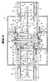
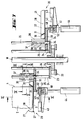
- FIGS. 4 to 12 show an exemplary embodiment of an exhaust air and drying station 8 or 10 or 11 according to the invention in various sections and detailed representations.
- the station is equipped with a series of support elements 20 for the printed circuit boards 2.
- these support elements 20 can be adjusted to the width B of the inserted printed circuit boards 2.
- the support elements 20 each comprise two support arms 21 which extend approximately parallel to the longitudinal edges 3 of an inserted circuit board 2. At least one of the support arms 21, according to the exemplary embodiment shown in FIG. 4, both support arms are displaceable transversely to their longitudinal extent.
- Each support element 20 is fastened to two roller chains 22 (FIGS.
- roller chains have chain links 23 which are provided with two bores 24.
- Two guide rods 25 and 26 are inserted into the two bores 24 of each chain link 23 and connect the two endlessly rotating roller chains.
- the support arms 21 of the support elements 20 can each be displaced in pairs on the guide rods connecting the two chains 22 (FIG. 4).
- each support arm 21 comprises a guide rail 27 with a longitudinal groove 28, which has an approximately V-shaped profile and an opening angle ⁇ of approximately 30 ° to 50 °, preferably approximately 40 °.
- the guide rail 27 is open at its end 29 remote from the chain 22, so that the longitudinal edge 3 of a printed circuit board 2 can be inserted.
- a stop 31 for the transverse edge 4 of an inserted circuit board is provided in the longitudinal groove 28 on the end face 30 facing the chain 22.
- the guide rails 27 of each pair of support arms 21 are arranged such that their longitudinal grooves 28 face each other and run approximately parallel to the longitudinal edges 3 of the printed circuit boards 2 to be inserted.
- the guide rails 27 are mounted on brackets 33 (FIG. 7) which is equipped with a bore 34 for receiving the guide rod 25 which is at the front in the insertion direction F of the printed circuit boards 2 in the support elements 20.
- brackets 33 FIG. 7
- the direction of insertion F of the printed circuit boards 2 into the support elements 20 of the exhaust air and drying device is identical to the essentially horizontal transport direction D of the printed circuit boards 2.
- the holders 33 At their rear end, have fork-like guides 35, each of which is the rear one Grip the guide rod 26 (FIGS. 9 and 10).
- This design feature has the advantage that at the deflection points of the endlessly rotating roller chains 22 there are no tensile stresses on the rear guide rods 26 or on the brackets 33.
- each holder 33 is equipped with a carriage 36 in the region of the bore 35.
- Each carriage 36 is equipped with rollers 37 which are arranged along the circumference of the front guide rod 25 and one behind the other in such a way that the holder 33 and with it the guide rail 27 can be displaced along the front guide rod 25 without tilting.
- the carriage 36 preferably comprises six rollers 37, which are distributed in two triple blocks over the length of the carriage.
- the rollers 37 of each roller triple are each offset from one another by an angle ⁇ of approximately 120 °, so that the rollers touch the guide rod 25 in mutually offset regions at approximately the same angle.
- each carriage 36 has a brake which is formed by a brake pad 38 which is pressed against the front guide rod 25 by a spring 39.
- the width of the support elements 20 is preferably pneumatic Moving at least one of the two support arms 21 of each support element 20.
- Two exemplary embodiments of these adjustment elements are shown in FIG.
- Mechanical adjusting means 21 are shown for adjusting the left arm 21 in the direction of insertion of the printed circuit boards 2.
- Pneumatic actuating means are indicated for the right support arm 21. It goes without saying that only either one - mechanical - or the other - pneumatic - adjusting means are provided for the adjustment of both support arms 21.
- Both adjustment means have in common that a stop 40, extension or the like is arranged on each holder 33, which, as shown in FIGS. 4 and 7, extends approximately parallel to the longitudinal extension of the guide rods 25, 26 to the outside.
- the stop 40 can be coupled to a plunger 50 of pneumatic transverse adjustment means 44 for the support arms 21.
- an adjusting arm 51 extends from the directional bars of the guide means 18 for the printed circuit boards in the coating station 7 parallel to the plate transport direction D in the direction of the entrance of the exhaust air and drying station 8.
- the adjusting arms 51 are together with the directional bars to the width B. of the transported circuit boards 2 adjustable.
- a plunger 50 is provided at the end of the actuating arm 51, which can be coupled to the stop 40.
- the stop 40 is provided with a bore 41 (FIGS. 7 and 11 or 12).
- the plunger 50 of the pneumatic transverse adjustment means 44 or the plunger at the end of the actuating arm 51 also has a bore 52.
- a locking pin 42 which can be actuated by a preferably pneumatic drive 43, can be inserted through the bores 41 and 52.
- the drive 43 is connected to the transverse adjusting means 44.
- the drive is fastened to the adjustment arm 51 and adjustable with it.
- the plunger 50 and the stop 40 can be locked together, and the support arm 21 can be pulled outwards again in order to enlarge the width of the support element again.
- the transverse adjustment means are mechanically coupled to the adjustment means for the width adjustment of the lateral guide means 19 in the coating station or they can be coupled in terms of control so that the width adjustment of the support elements 20 takes place as a function of the width adjustment of the lateral guide means.
- a support member 32 preferably extends away from the guide rods 25, 26 for the leading transverse edge 4 of an inserted circuit board.
- This support member 32 extends below the insertion level through the transport plane T of Printed circuit boards is defined in the coating station, up to approximately an area which corresponds approximately to the imaginary connecting line of the rear end stops 31 in the longitudinal grooves of the guide rails 27 of a pair of support arms 21.
- the support member is in a region which extends from approximately the first quarter to approximately over the third quarter of length 1 of the guide rods 25, 26 and is preferably approximately in the region of half the length 1 of the guide rods 25, 26 on the circumference of the guide rods 25, 26 attached.
- the support member 32 extends to the leading transverse edge 4 of the inserted circuit board and supports its underside in such a way that even thin boards do not sag.
- device-specific feed means 45 for the printed circuit boards 2 are provided at the entrance and exit of the exhaust air and drying station, with the aid of which the printed circuit boards 2 are conveyed from the transport means of the previous processing station can be taken over and inserted into the support elements 20 or can be pushed out of the support elements 20 again after turning the circuit boards 2.
- These feed means 45 are arranged below the horizontal transport plane T of the printed circuit boards 2. They comprise a sliding element 46 which engages on the rear transverse edge 4 of the printed circuit boards 2 in relation to the transport direction D.
- a preferably pneumatic drive 47 allows the sliding element 46 to be adjusted in or against the transport direction D of the printed circuit boards 2.
- guide channels 49 can also be provided for the printed circuit boards 2 at the entrance and exit of the exhaust air and drying station be. These are preferably connected to the lateral guide elements 18 of the coating stations. Preferably, they are short V-shaped guide rails, each of which is slightly curved outwards on the input side in order to present an approximately funnel-shaped inlet section to an incoming plate.
- the circuit boards 2 are heated in the preheating station 6 for coating.
- no special support elements 17 are required, which only grip the printed circuit boards at the longitudinal edges, since the boards are not yet coated.
- the plates can therefore be transported, for example, in support elements with horizontal tines protruding from two spars. When turning, the plates simply tilt onto the back of the leading support element 17 are transported downwards and placed on the transfer roller conveyor 14.
- the printed circuit boards reach the first coating station 7 from the transfer roller conveyor 14 gripped lateral guide means 18 on their longitudinal edges 3, aligned and transported under the curtain 16. They are always guided along their longitudinal edges 3.
- the printed circuit boards 2 arrive in the feed area of the feed means 45, which feed the printed circuit boards 2, which are now coated on one side, into the support elements 20 of the first exhaust air which have already been adjusted in terms of their width depending on the width adjustment of the lateral guide means 18 in the first coating station 7. and inserts drying station 8.
- the coated surface of the printed circuit boards 2 is dried to such an extent that the coating C does not run or run off when the boards are turned, where they are vertical for a short time.
- further feed means 45 pull them out of the support elements at the exit of the station. If the plates are to be coated only on one side, they arrive at the discharge roller conveyor 13, from where they can be transported to further processing stations.
- the plates are transferred from the feed means 45 starting from the first exhaust air and drying station 8 to the lateral guide means 18 of the second coating station 9. Holding and guided laterally, the printed circuit boards 2 are again transported under the casting curtain 16 and the second surface is coated. It should be noted that the circuit board 2 is always held and guided only at its longitudinal edges 3. The surface that has already been coated never comes into contact with the means of transport. Leaving the second coating station 9, the printed circuit boards 2 reach the feed area of the feed means 45 of the second exhaust air and drying station 10, which the printed circuit boards 2, which are now coated on one side, in terms of their width depending on the width adjustment of the lateral guide means 18 in the second coating station 9 inserted support elements 20 of the second exhaust and drying station 10.
- the second coated surface of the printed circuit boards 2 is dried to such an extent that the coating C does not run or run off when the boards are turned, where they are vertical for a short time.
- the already pre-dried first coated surface is further dried so that the plates can be deposited with this surface at the exit of the station without damaging the coating C.
- further feed means 45 pull them out of the support elements at the station and transfer them to the output roller conveyor 13. If the throughput speed of the printed circuit boards 2 through the continuous dryer is so high that the lower surface on the outlet side has not yet dried sufficiently, the printed circuit boards 2 can be transferred to a further third drying station 11 at the outlet of the second exhaust air and drying station 10.
- Transport means 48 are provided for this purpose, which push the printed circuit boards out of the transport elements 20 of the one station and into the transport elements 20 of the following station.
- These transport means 48 preferably comprise feed means 45 which are constructed in the same way as the transport means on the entrance side of the preceding station.
- lateral guides can also be provided, the mutual distance of which is adjustable depending on the width B of the printed circuit boards 2. After passing through the third exhaust air and drying station 11, the surfaces of the printed circuit boards 2 have dried sufficiently that the coatings C can no longer be damaged by lying transport.
- the printed circuit boards 2 are aligned only once, directly at the beginning of the first coating station. From this point in time, the printed circuit boards 2 are always supported and guided by the various transport means of the various processing stations only on the lateral edges. Even when the circuit boards 2 coated on one or both sides are transferred from one processing station of the coating system to the next, the circuit boards 2 are essentially guided and supported at their coating-free longitudinal edges 3. The plates are not clamped or held. A support member supports the leading transverse edge 4 of the printed circuit boards 2 during the heat treatment, so that even for thin printed circuit boards 2 an injury-free transport through the exhaust air and drying station (s) is ensured.
Landscapes
- Engineering & Computer Science (AREA)
- Manufacturing & Machinery (AREA)
- Microelectronics & Electronic Packaging (AREA)
- Coating Apparatus (AREA)
- Non-Metallic Protective Coatings For Printed Circuits (AREA)
- Reinforced Plastic Materials (AREA)
Applications Claiming Priority (2)
| Application Number | Priority Date | Filing Date | Title |
|---|---|---|---|
| CH263692 | 1992-08-24 | ||
| CH2636/92 | 1992-08-24 |
Publications (2)
| Publication Number | Publication Date |
|---|---|
| EP0585204A1 true EP0585204A1 (fr) | 1994-03-02 |
| EP0585204B1 EP0585204B1 (fr) | 1996-09-25 |
Family
ID=4238219
Family Applications (1)
| Application Number | Title | Priority Date | Filing Date |
|---|---|---|---|
| EP93810577A Expired - Lifetime EP0585204B1 (fr) | 1992-08-24 | 1993-08-16 | Procédé et dispositif pour le revêtement d'objets en forme de plaques en particulier cartes de circuit imprimé |
Country Status (9)
| Country | Link |
|---|---|
| US (1) | US5462599A (fr) |
| EP (1) | EP0585204B1 (fr) |
| JP (1) | JP3203455B2 (fr) |
| KR (1) | KR100275232B1 (fr) |
| AT (1) | ATE143565T1 (fr) |
| DE (1) | DE59303954D1 (fr) |
| ES (1) | ES2092799T3 (fr) |
| HK (1) | HK1005204A1 (fr) |
| TW (1) | TW220028B (fr) |
Cited By (3)
| Publication number | Priority date | Publication date | Assignee | Title |
|---|---|---|---|---|
| EP0730396A1 (fr) * | 1995-03-03 | 1996-09-04 | Ford Motor Company | Système et méthode d'assemblage de circuits imprimés |
| WO1997007924A1 (fr) * | 1995-08-29 | 1997-03-06 | Soltec B.V. | Dispositif de soudage par refusion a configuration rotative |
| CN101979153A (zh) * | 2010-10-11 | 2011-02-23 | 李荣根 | 全自动水平式pcb板双面涂布机 |
Families Citing this family (13)
| Publication number | Priority date | Publication date | Assignee | Title |
|---|---|---|---|---|
| ATE133531T1 (de) * | 1992-09-28 | 1996-02-15 | Ciba Geigy Ag | Verfahren und vorrichtung zur beidseitigen beschichtung von plattenförmigem stückgut |
| US6258165B1 (en) * | 1996-11-01 | 2001-07-10 | Speedline Technologies, Inc. | Heater in a conveyor system |
| TW416261B (en) * | 1997-04-24 | 2000-12-21 | Ciba Sc Holding Ag | Process and apparatus for the treatment of coated printed circuit boards |
| DE10151708A1 (de) * | 2001-10-19 | 2003-05-08 | All4 Pcb Switzerland Ltd | Verfahren zum Aufnehmen von horizontal geförderten Platten in einer Puffervorrichtung sowie Puffervorrichtung |
| US6760981B2 (en) | 2002-01-18 | 2004-07-13 | Speedline Technologies, Inc. | Compact convection drying chamber for drying printed circuit boards and other electronic assemblies by enhanced evaporation |
| US20060273138A1 (en) * | 2005-06-07 | 2006-12-07 | Samsung Electronics Co., Ltd. | Soldering apparatus for printed circuit board, soldering method for printed circuit board and soldering cream printing unit for soldering printed circuit board |
| KR100862343B1 (ko) * | 2007-05-29 | 2008-10-13 | 삼성전기주식회사 | 조명용 led 모듈 및 그 제조방법 |
| KR101030268B1 (ko) | 2010-11-12 | 2011-04-21 | (주)유창 | 광촉매 코팅장치 및 이를 이용한 광촉매 코팅방법 |
| CN106696475B (zh) * | 2015-11-13 | 2019-06-18 | 富泰华工业(深圳)有限公司 | 打印机及利用打印机打印电路板的方法 |
| CN110497701B (zh) * | 2018-05-18 | 2021-01-29 | 富泰华工业(深圳)有限公司 | 立式电路板打印机及其打印方法 |
| CN113636270A (zh) * | 2021-08-04 | 2021-11-12 | 深圳市宏讯实业有限公司 | 一种氛围连续加工设备 |
| CN113492076B (zh) * | 2021-09-10 | 2021-11-09 | 南通普力新机械科技有限公司 | 不锈钢板保护剂喷涂设备 |
| CN114980542B (zh) * | 2022-05-24 | 2023-11-10 | 东莞市黄江大顺电子有限公司 | 一种新能源汽车印刷电路板制造用设备 |
Citations (3)
| Publication number | Priority date | Publication date | Assignee | Title |
|---|---|---|---|---|
| DE3539959A1 (de) * | 1985-11-11 | 1987-05-21 | Weber Erich Dipl Ing Fh | Verfahren zum transportieren von leiterplatten durch trocknungsanlagen und vorrichtung zur durchfuehrung dieses verfahrens |
| DE3738067A1 (de) * | 1987-11-09 | 1989-05-18 | Wolfgang Anger | Einrichtung zum mehrfachen beschichten von platten |
| DE4107224C1 (fr) * | 1991-03-07 | 1992-06-04 | Dupont De Nemours Gmbh, 6380 Bad Homburg, De |
Family Cites Families (12)
| Publication number | Priority date | Publication date | Assignee | Title |
|---|---|---|---|---|
| DE2802339A1 (de) * | 1978-01-20 | 1979-07-26 | Paper Converting Machine Co | Vorrichtung zur zwischenpufferung auf paletten |
| CH641708A5 (de) * | 1979-11-02 | 1984-03-15 | Sinter Ltd | Vorrichtung zum aufbringen von lot auf leiterplatten. |
| US4559896A (en) * | 1983-09-15 | 1985-12-24 | Ciba Geigy Corporation | Coating apparatus |
| ES2009804B3 (es) * | 1985-11-08 | 1989-10-16 | Ciba Specialty Chemicals Holding Inc | Dispositivo de transporte para placas. |
| DE3602350C2 (de) * | 1986-01-27 | 1994-08-18 | Weber Marianne | Verfahren und Anlage zum beidseitigen Beschichten von Platten mit flüssigem Beschichtungsmaterial |
| DE3721404A1 (de) * | 1987-06-29 | 1989-01-12 | Kopperschmidt Mueller & Co | Vorrichtung zur elektrostatischen spruehbeschichtung von plattenfoermigen werkstuecken |
| US4926789A (en) * | 1987-10-13 | 1990-05-22 | Ciba-Geigy Corporation | Transport apparatus for boards |
| EP0421931A1 (fr) * | 1989-10-06 | 1991-04-10 | Ciba-Geigy Ag | Appareil de transport de plaques, en particulier ayant des surfaces sensibles |
| DE3937071A1 (de) * | 1989-11-07 | 1991-05-08 | Kopperschmidt Mueller & Co | Vorrichtung und verfahren zum beschichten von plattenfoermigen substraten, wie leiterplatten |
| EP0441743A1 (fr) * | 1990-02-05 | 1991-08-14 | Ciba-Geigy Ag | Dispositif de transport pour plaques à surface sensible, en particulier pour circuits imprimÀ©s à recouvrement humide |
| US5188669A (en) * | 1991-02-22 | 1993-02-23 | Nordson Corporation | Circuit board coating apparatus with inverting pallet shuttle |
| EP0542684B1 (fr) * | 1991-11-13 | 1997-04-09 | Ciba-Geigy Ag | Dispositif de revêtement de plaques |
-
1993
- 1993-08-06 TW TW082106305A patent/TW220028B/zh active
- 1993-08-16 ES ES93810577T patent/ES2092799T3/es not_active Expired - Lifetime
- 1993-08-16 EP EP93810577A patent/EP0585204B1/fr not_active Expired - Lifetime
- 1993-08-16 AT AT93810577T patent/ATE143565T1/de not_active IP Right Cessation
- 1993-08-16 DE DE59303954T patent/DE59303954D1/de not_active Expired - Fee Related
- 1993-08-19 US US08/109,282 patent/US5462599A/en not_active Expired - Fee Related
- 1993-08-20 KR KR1019930016193A patent/KR100275232B1/ko not_active Expired - Fee Related
- 1993-08-24 JP JP23095993A patent/JP3203455B2/ja not_active Expired - Fee Related
-
1998
- 1998-05-19 HK HK98104343A patent/HK1005204A1/xx not_active IP Right Cessation
Patent Citations (3)
| Publication number | Priority date | Publication date | Assignee | Title |
|---|---|---|---|---|
| DE3539959A1 (de) * | 1985-11-11 | 1987-05-21 | Weber Erich Dipl Ing Fh | Verfahren zum transportieren von leiterplatten durch trocknungsanlagen und vorrichtung zur durchfuehrung dieses verfahrens |
| DE3738067A1 (de) * | 1987-11-09 | 1989-05-18 | Wolfgang Anger | Einrichtung zum mehrfachen beschichten von platten |
| DE4107224C1 (fr) * | 1991-03-07 | 1992-06-04 | Dupont De Nemours Gmbh, 6380 Bad Homburg, De |
Cited By (5)
| Publication number | Priority date | Publication date | Assignee | Title |
|---|---|---|---|---|
| EP0730396A1 (fr) * | 1995-03-03 | 1996-09-04 | Ford Motor Company | Système et méthode d'assemblage de circuits imprimés |
| WO1997007924A1 (fr) * | 1995-08-29 | 1997-03-06 | Soltec B.V. | Dispositif de soudage par refusion a configuration rotative |
| US6096999A (en) * | 1995-08-29 | 2000-08-01 | Soltec B.V. | Reflow soldering apparatus with a rotative configuration |
| CN101979153A (zh) * | 2010-10-11 | 2011-02-23 | 李荣根 | 全自动水平式pcb板双面涂布机 |
| CN101979153B (zh) * | 2010-10-11 | 2012-10-03 | 李荣根 | 全自动水平式pcb板双面涂布机 |
Also Published As
| Publication number | Publication date |
|---|---|
| JPH06182284A (ja) | 1994-07-05 |
| ES2092799T3 (es) | 1996-12-01 |
| TW220028B (en) | 1994-02-01 |
| KR100275232B1 (ko) | 2001-01-15 |
| US5462599A (en) | 1995-10-31 |
| DE59303954D1 (de) | 1996-10-31 |
| EP0585204B1 (fr) | 1996-09-25 |
| KR940005197A (ko) | 1994-03-16 |
| ATE143565T1 (de) | 1996-10-15 |
| HK1005204A1 (en) | 1998-12-24 |
| JP3203455B2 (ja) | 2001-08-27 |
Similar Documents
| Publication | Publication Date | Title |
|---|---|---|
| EP0585204B1 (fr) | Procédé et dispositif pour le revêtement d'objets en forme de plaques en particulier cartes de circuit imprimé | |
| DE4107224C1 (fr) | ||
| DE3532553C1 (de) | Verfahren und Vorrichtung zum Abziehen der Schutzfolie von einer mit belichtetem Fotoresist beschichteten Leiterplatte | |
| DE3039582C2 (de) | Vorrichtung zum gleichzeitigen Aufbringen von Lot auf beiden Seiten von Leiterplatten | |
| DE69807823T2 (de) | Heizformvorrichtung mit gerader Förderung von umlaufenden Folienhalterahmen | |
| EP0592745B1 (fr) | Procédé et dispositif pour le revêtement à deux faces d'articles en forme de plaques | |
| EP0312498B1 (fr) | Méthode de transport de plaques | |
| DD211963A5 (de) | Vorrichtung zur sortierung laenglicher teile | |
| DE3306815C2 (de) | Vorrichtung zum transportieren von in einer schuppenformation anfallenden flaechigen erzeugnissen, insbesondere druckprodukten | |
| DE69802676T2 (de) | Vorrichtung zum beschichten von plattenförmigen substraten, insbesondere von leiterplatten | |
| EP0441743A1 (fr) | Dispositif de transport pour plaques à surface sensible, en particulier pour circuits imprimÀ©s à recouvrement humide | |
| DE3539959A1 (de) | Verfahren zum transportieren von leiterplatten durch trocknungsanlagen und vorrichtung zur durchfuehrung dieses verfahrens | |
| DE60202002T2 (de) | Verfahren und vorrichtung zum einwickeln von druckerzeugnissen | |
| EP0542684B1 (fr) | Dispositif de revêtement de plaques | |
| EP0421931A1 (fr) | Appareil de transport de plaques, en particulier ayant des surfaces sensibles | |
| EP2942432A1 (fr) | Pince à linge | |
| DE4314644A1 (de) | Vorrichtung zum Ablegen flacher Gegenstände in Hochkantlage auf einem Transportband oder dergleichen | |
| DE19925819A1 (de) | Vorrichtung zum Beschichten von Leiterplatten | |
| EP1535867B1 (fr) | Dispositif et procédé d'avance pour des balles ou des bottes de tabac | |
| DE19805574B4 (de) | Verfahren und Vorrichtung zum Transport und zur Vorbereitung von hohlen Profilstäben aus Kunststoff für die Bildung von Fensterrahmen | |
| DE19654857A1 (de) | Vorrichtung zum Trennen und seitlichem Auslenken durch Längsschnitt erzeugten Metallstreifen | |
| EP0084077B1 (fr) | Dispositif pour transporter automatiquement des plaques supports circuits imprimés à des installations d'étendage au rouleau | |
| DE8503321U1 (de) | Vorrichtung zur beschichtung von platten | |
| DE20304714U1 (de) | Vorrichtung zur Aufteilung von länglichen Körpern | |
| DE2656116C3 (de) | Vorrichtung zum stapelweisen Ablegen von flexiblen Paneelen auf einem unterhalb eines Endlosförderers angeordneten Stapeltisch |
Legal Events
| Date | Code | Title | Description |
|---|---|---|---|
| PUAI | Public reference made under article 153(3) epc to a published international application that has entered the european phase |
Free format text: ORIGINAL CODE: 0009012 |
|
| AK | Designated contracting states |
Kind code of ref document: A1 Designated state(s): AT BE CH DE ES FR GB IT LI NL SE |
|
| 17P | Request for examination filed |
Effective date: 19940810 |
|
| 17Q | First examination report despatched |
Effective date: 19950630 |
|
| GRAH | Despatch of communication of intention to grant a patent |
Free format text: ORIGINAL CODE: EPIDOS IGRA |
|
| GRAH | Despatch of communication of intention to grant a patent |
Free format text: ORIGINAL CODE: EPIDOS IGRA |
|
| GRAA | (expected) grant |
Free format text: ORIGINAL CODE: 0009210 |
|
| AK | Designated contracting states |
Kind code of ref document: B1 Designated state(s): AT BE CH DE ES FR GB IT LI NL SE |
|
| REF | Corresponds to: |
Ref document number: 143565 Country of ref document: AT Date of ref document: 19961015 Kind code of ref document: T |
|
| ET | Fr: translation filed | ||
| REF | Corresponds to: |
Ref document number: 59303954 Country of ref document: DE Date of ref document: 19961031 |
|
| REG | Reference to a national code |
Ref country code: CH Ref legal event code: PUE Owner name: CIBA-GEIGY AG TRANSFER- CIBA SC HOLDING AG |
|
| REG | Reference to a national code |
Ref country code: ES Ref legal event code: FG2A Ref document number: 2092799 Country of ref document: ES Kind code of ref document: T3 |
|
| ITF | It: translation for a ep patent filed | ||
| BECA | Be: change of holder's address |
Free format text: 960925 *CIBA SC HOLDING A.G.:KLYBECKSTRASSE 141, CH - 4057 BALE |
|
| BECH | Be: change of holder |
Free format text: 960925 *CIBA SC HOLDING A.G. |
|
| BECN | Be: change of holder's name |
Effective date: 19961129 |
|
| GBT | Gb: translation of ep patent filed (gb section 77(6)(a)/1977) |
Effective date: 19961220 |
|
| REG | Reference to a national code |
Ref country code: FR Ref legal event code: TP |
|
| REG | Reference to a national code |
Ref country code: GB Ref legal event code: 732E |
|
| REG | Reference to a national code |
Ref country code: CH Ref legal event code: PFA Free format text: CIBA SC HOLDING AG TRANSFER- CIBA SPECIALTY CHEMICALS HOLDING INC. |
|
| REG | Reference to a national code |
Ref country code: FR Ref legal event code: CD |
|
| NLS | Nl: assignments of ep-patents |
Owner name: CIBA SPECIALTY CHEMICALS HOLDING INC.;NOVARTIS AG |
|
| PLBE | No opposition filed within time limit |
Free format text: ORIGINAL CODE: 0009261 |
|
| STAA | Information on the status of an ep patent application or granted ep patent |
Free format text: STATUS: NO OPPOSITION FILED WITHIN TIME LIMIT |
|
| 26N | No opposition filed | ||
| REG | Reference to a national code |
Ref country code: ES Ref legal event code: PC2A |
|
| REG | Reference to a national code |
Ref country code: CH Ref legal event code: PUE Owner name: CIBA SPECIALTY CHEMICALS HOLDING INC. TRANSFER- VA |
|
| REG | Reference to a national code |
Ref country code: GB Ref legal event code: 732E |
|
| NLS | Nl: assignments of ep-patents |
Owner name: VANTICO AG |
|
| REG | Reference to a national code |
Ref country code: GB Ref legal event code: IF02 |
|
| PGFP | Annual fee paid to national office [announced via postgrant information from national office to epo] |
Ref country code: CH Payment date: 20020717 Year of fee payment: 10 |
|
| PGFP | Annual fee paid to national office [announced via postgrant information from national office to epo] |
Ref country code: SE Payment date: 20020725 Year of fee payment: 10 Ref country code: NL Payment date: 20020725 Year of fee payment: 10 |
|
| PGFP | Annual fee paid to national office [announced via postgrant information from national office to epo] |
Ref country code: BE Payment date: 20020726 Year of fee payment: 10 |
|
| PGFP | Annual fee paid to national office [announced via postgrant information from national office to epo] |
Ref country code: AT Payment date: 20020729 Year of fee payment: 10 |
|
| PGFP | Annual fee paid to national office [announced via postgrant information from national office to epo] |
Ref country code: GB Payment date: 20020730 Year of fee payment: 10 |
|
| PGFP | Annual fee paid to national office [announced via postgrant information from national office to epo] |
Ref country code: ES Payment date: 20020809 Year of fee payment: 10 Ref country code: DE Payment date: 20020809 Year of fee payment: 10 |
|
| PGFP | Annual fee paid to national office [announced via postgrant information from national office to epo] |
Ref country code: FR Payment date: 20020812 Year of fee payment: 10 |
|
| REG | Reference to a national code |
Ref country code: FR Ref legal event code: TP |
|
| PG25 | Lapsed in a contracting state [announced via postgrant information from national office to epo] |
Ref country code: GB Free format text: LAPSE BECAUSE OF NON-PAYMENT OF DUE FEES Effective date: 20030816 Ref country code: AT Free format text: LAPSE BECAUSE OF NON-PAYMENT OF DUE FEES Effective date: 20030816 |
|
| PG25 | Lapsed in a contracting state [announced via postgrant information from national office to epo] |
Ref country code: SE Free format text: LAPSE BECAUSE OF NON-PAYMENT OF DUE FEES Effective date: 20030817 |
|
| PG25 | Lapsed in a contracting state [announced via postgrant information from national office to epo] |
Ref country code: ES Free format text: LAPSE BECAUSE OF NON-PAYMENT OF DUE FEES Effective date: 20030818 |
|
| PG25 | Lapsed in a contracting state [announced via postgrant information from national office to epo] |
Ref country code: LI Free format text: LAPSE BECAUSE OF NON-PAYMENT OF DUE FEES Effective date: 20030831 Ref country code: CH Free format text: LAPSE BECAUSE OF NON-PAYMENT OF DUE FEES Effective date: 20030831 Ref country code: BE Free format text: LAPSE BECAUSE OF NON-PAYMENT OF DUE FEES Effective date: 20030831 |
|
| BERE | Be: lapsed |
Owner name: *VANTICO A.G. Effective date: 20030831 |
|
| PG25 | Lapsed in a contracting state [announced via postgrant information from national office to epo] |
Ref country code: NL Free format text: LAPSE BECAUSE OF NON-PAYMENT OF DUE FEES Effective date: 20040301 |
|
| PG25 | Lapsed in a contracting state [announced via postgrant information from national office to epo] |
Ref country code: DE Free format text: LAPSE BECAUSE OF NON-PAYMENT OF DUE FEES Effective date: 20040302 |
|
| EUG | Se: european patent has lapsed | ||
| GBPC | Gb: european patent ceased through non-payment of renewal fee |
Effective date: 20030816 |
|
| REG | Reference to a national code |
Ref country code: CH Ref legal event code: PL |
|
| PG25 | Lapsed in a contracting state [announced via postgrant information from national office to epo] |
Ref country code: FR Free format text: LAPSE BECAUSE OF NON-PAYMENT OF DUE FEES Effective date: 20040430 |
|
| NLV4 | Nl: lapsed or anulled due to non-payment of the annual fee |
Effective date: 20040301 |
|
| REG | Reference to a national code |
Ref country code: FR Ref legal event code: ST |
|
| REG | Reference to a national code |
Ref country code: ES Ref legal event code: FD2A Effective date: 20030818 |
|
| PG25 | Lapsed in a contracting state [announced via postgrant information from national office to epo] |
Ref country code: IT Free format text: LAPSE BECAUSE OF NON-PAYMENT OF DUE FEES;WARNING: LAPSES OF ITALIAN PATENTS WITH EFFECTIVE DATE BEFORE 2007 MAY HAVE OCCURRED AT ANY TIME BEFORE 2007. THE CORRECT EFFECTIVE DATE MAY BE DIFFERENT FROM THE ONE RECORDED. Effective date: 20050816 |