EP0585471A1 - Werkzeuggreifer - Google Patents
Werkzeuggreifer Download PDFInfo
- Publication number
- EP0585471A1 EP0585471A1 EP93906795A EP93906795A EP0585471A1 EP 0585471 A1 EP0585471 A1 EP 0585471A1 EP 93906795 A EP93906795 A EP 93906795A EP 93906795 A EP93906795 A EP 93906795A EP 0585471 A1 EP0585471 A1 EP 0585471A1
- Authority
- EP
- European Patent Office
- Prior art keywords
- pair
- tool
- holder
- tool holder
- holder base
- Prior art date
- Legal status (The legal status is an assumption and is not a legal conclusion. Google has not performed a legal analysis and makes no representation as to the accuracy of the status listed.)
- Withdrawn
Links
- 238000005096 rolling process Methods 0.000 claims abstract description 19
- 238000013459 approach Methods 0.000 claims description 6
- 238000003754 machining Methods 0.000 description 3
- 238000010276 construction Methods 0.000 description 2
- 238000000034 method Methods 0.000 description 2
- 230000000694 effects Effects 0.000 description 1
- 230000007257 malfunction Effects 0.000 description 1
- 238000000465 moulding Methods 0.000 description 1
Images

Classifications
-
- B—PERFORMING OPERATIONS; TRANSPORTING
- B23—MACHINE TOOLS; METAL-WORKING NOT OTHERWISE PROVIDED FOR
- B23Q—DETAILS, COMPONENTS, OR ACCESSORIES FOR MACHINE TOOLS, e.g. ARRANGEMENTS FOR COPYING OR CONTROLLING; MACHINE TOOLS IN GENERAL CHARACTERISED BY THE CONSTRUCTION OF PARTICULAR DETAILS OR COMPONENTS; COMBINATIONS OR ASSOCIATIONS OF METAL-WORKING MACHINES, NOT DIRECTED TO A PARTICULAR RESULT
- B23Q3/00—Devices holding, supporting, or positioning work or tools, of a kind normally removable from the machine
- B23Q3/155—Arrangements for automatic insertion or removal of tools, e.g. combined with manual handling
- B23Q3/157—Arrangements for automatic insertion or removal of tools, e.g. combined with manual handling of rotary tools
- B23Q3/15706—Arrangements for automatic insertion or removal of tools, e.g. combined with manual handling of rotary tools a single tool being inserted in a spindle directly from a storage device, i.e. without using transfer devices
Definitions
- the invention relates to a device for gripping a tool holder.
- the invention relates to a device for gripping a tool holder which device cooperates with a tool magazine of an automatic machine tool, such as a machining center, provided with an automatic tool changer (in the following referred to as an ATC).
- an ATC automatic tool changer
- the device detachably grips a tool holder holding a tool such as a cutter tool.
- the device can smoothly mount the tool holder holding the tool, selected by the indexing the tool magazine based on a requirement, to a spindle of the machining center through the movement of the machining center, and can also return the tool holder from the spindle to the tool magazine.
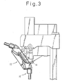
- a typical machining center comprises, as shown in Figure 3, a tool magazine 13 which has a plurality of devices for gripping tool holders. The devices are equally spaced around the tool magazine. Tools used for machining process are held by the respective tool holders and accommodated within the tool magazine 13.
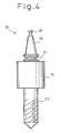
- the tool 20 used with a machining center is fitted into the tool holder 15 from the end of the holder and held by the tool holder 15.
- the tool holder 15 comprises a holder head 16 holding the tool 20, a V-shaped groove 17 adapted to engage with a gripping portion of the device and to be gripped by the device for gripping a tool, a tapered shank 18 adapted to be complementarily fitted into a tapered bore of a spindle 14, and a pull stud 19 for lifting the tapered shank 18 into the spindle.
- the desired tools are selected, based on a machining program, prior to the machining process. Then, the selected tools are mounted into the respective tool holders 15 by the operator.
- the tool holders 15 are manually mounted onto the devices for gripping a tool holder with the V-shaped groove of each holder engaged with the gripping portion of each device.
- the tools will be automatically moved between the spindle and the tool magazine as described below. Firstly, the device approaches the spindle 14 of the machining center by the swing movement of the tool magazine 13, then the device engages with the V-shaped groove 17 of the tool holder mounted onto the spindle and grips the tool holder 15.
- the tool holder 15 is withdrawn from the spindle 14 when the spindle 14 rises.
- the tool which has finished its work, is returned to its normal position.
- a required tool 20 is selected by the indexing the magazine 13.
- the tool holder 15 holding the tool 20 is moved, until it is directly below the spindle 14, by the the magazine 13 swinging.
- the tapered shank 18 of the tool holder 15 is fitted into the bore of the spindle 14 when the spindle 14 is lowered. This terminates the tool change.
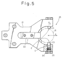
- Figure 5 illustrates a device for gripping a tool holder of the prior art.
- the device comprises a generally flat grip 21 having a generally U-shaped gripping portion 26 on one end thereof.
- a bore is made at each end portion of a pair of branched portions of the gripping portion 26 of the grip 21.
- a pair of fingers 23 and a pair of springs 24 are inserted into the bores.
- the fingers 23 and the springs 24 are secured from the rear side by caps 25.
- the pair of fingers 23 are biased in the opposite directions to each other, that is, in the directions toward the V-shaped groove, not shown, of the tool holder 15 illustrated by the dotted line.
- Such construction allows the fingers 23, when the tool holder 15 is manually mounted or removed, to move in the direction indicated by an arrow C with the tips of the fingers engaging with the V-shaped groove, whereby the tool holder 15 can move in the direction indicated by an arrow A.
- the tool holder of the prior art described above is widely used because the construction is relatively simple.
- the tool holder has the disadvantages described below.
- the conventional tool holder has limited space for the fingers and the springs, which may be seen from Figure 5. Therefore, the dimensions of these components are also limited, thus it is difficult to ensure the sufficient grip force to grip the tool and the tool holder which have considerable weight. This leads to the malfunctions, such as dropping of the tool during the tool change or during the indexing of the tool magazine 13, and the reliability of the tool change function of the machining center is reduced.
- the fingers 23 are forced by the movement of the tool holder in the direction indicated by the arrow A, against the bores at positions "D", by the tool holder to be mounted, and at the same time, the fingers 23 are moved in the direction indicated by the arrow C. Therefore, at the positions D, the fingers 23 and the bores of the grip 21 tends to be worn. Additionally, portions E of the fingers 23 which contact to the tool holder 15 are also worn by the friction therebetween. Such wear reduces the life time of the device and lowers the reliability of the machining center.
- the object of the invention is to provide a device for gripping a tool holder which can apply a high gripping force, as compared with the conventional device, while the device of the invention makes the mounting and the releasing operation easier. Additionally, the object of the invention is to provide a device for gripping a tool holder which is adapted to reduce the friction between the device and the tool holder to be mounted during the mounting and the releasing operation, whereby the wear at the contact portions therebetween is reduced.
- a device for detachably gripping a tool holder holding a tool comprises: a generally flat holder base means; two arms, each extending at each side of the holder base means in the longitudinal direction along the side of the holder base means and attached for rotation about pivot pins arranged perpendicular to the plane of the holder base means; a pair of rolling means attached to the leading end of the each arms for rotation, the rolling means arranged so as to engage with a groove provided in the tool holder and to grip it; a spring means positioned at the rear portion of the holder base, the spring means biasing the arms so that the leading end of the respective arms approach each other; and the tool holder being gripped by the leading end of the holder base means and the pair of rolling means.
- the spring means are clamped between a pair of first heads provided at the rear end of the respective arms and a pair of second heads provided at a rear portions in the holder base means facing the respective first heads.
- the spring means may be a pair of coil springs.
- the spring means is a single coil spring inserted into a through hole provided at a rear portion of the holder base means and the coil spring biases the rear end of the each arm away from the other.
- the pair of rolling means are rollers which are attached to a pair of pins for rotation, and the pair of pins are fitted into a pair of bores provided at the leading end of the respective arms.
- the holder base means is provided an attachment means and is secured to a tool magazine of an automatic tool changer by the attachment means.
- the attachment means is preferably formed into one piece with the holder base means.
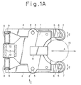
- a device for gripping a tool holder of the invention has a generally U-shaped gripping portion for gripping a tool holder similar to the prior art.
- a tool holder 15, illustrated by dotted line, is manually detachably mounted onto the gripping portion in the direction indicated by an arrow A. That is, the device in accordance with the invention comprises a generally flat holder base 1 having a position key 11, and the tool holder 15 is mounted onto the device so that its center axis is substantially perpendicular to the plane of the holder base 1 with a key groove (not shown but formed at a V-shaped groove 17) fitted to the key 11.
- the holder base 1 comprises an attachment member 12 for mounting the device to a tool magazine 13.
- the device is secured, as shown in Figure 3, to a turret base in the tool magazine 13 by the attachment member 12 in a known manner.
- the attachment member 12 is molded in one piece with the holder base 1 so that when a tool is selected by the magazine 13 and the tool and the tool holder 15 is moved to directly below the spindle of the machining center, the center axis of the tool and the tool holder 15 is aligned with the center axis of the spindle.
- the holder base 1 is provided with a pair of bores 2 which are symmetrically positioned at the either side of the holder base, and are substantially perpendicular to the plane of the holder base 1.
- Pins 3 are fitted into the respective bores 2 in a known manner.
- a pair of arms 4 are extended along the longitudinal direction of the holder base 1 and are pivotary mounted about the respective pins 3 at the either side of the holder base 1.
- the pair of the arms 4 are mounted by the pins 3 in a known manner.
- each arm 4 may be provided with a bore, not shown, for the pin 3, and be mounted to the pin 3 fitted into the bore. Additionally, sleeves may be advantageously fitted into the respective bores in order to reduce the friction between the pins 3 and the arms 4.
- a pair of rolling elements 7 are secured for rotation at the end of the respective arms 4 where the tool holder is mounted (right-hand side of Figure 1).
- the rolling elements 7 function to engage with the V-shaped groove 17 of the tool holder 15 and to grip the tool holder 15.
- the pair of rolling elements 7 are formed into roller members chamfered along their peripheries so as to correspond to the configuration of the V-shaped groove 17.
- the rolling elements 7 may be spherical members, not shown, or elongated cylindrical roller members, not shown, longer than the rolling elements 7 illustrated.
- roller members 7 are secured for rotation about a pair of pins 6 which, in a known manner, are fitted into a pair of bores 5 provided at the end of the respective arms 4. Additionally, sleeves may be advantageously used in order to reduce the friction between the roller members 7 and the pins 6.
- the arms 4 are provided with a pair of first heads 9 respectively at the end opposite to the roller members 7 in order to seat a pair of spring means 8.
- the holder base 1 is provided with a pair of second heads 10 at positions facing the respective first heads 9 in the either sides thereof in order to seat the spring means 8.
- the pair of spring means 8 are positioned and clamped between the respective first and second heads 9 and 10.
- the spring means 8 bias the arms 4 so that the pair of roller members 7 approach each other, whereby the roller members 7 engage and grip the tool holder 15.
- the first heads 9 are molded in one piece with the arms 4 by a known molding method, such as lost wax method, so as to clamp the spring means 8 securely in cooperation with the respective second heads 10.
- the pair of second heads 10 slightly project from the side faces of the holder base 1 in Figure 1.
- the projecting second heads 10 may be replaced by recessed heads, not shown, positioned to face the respective first heads 9, on either side of the holder base 1.
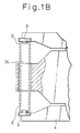
- the pair of spring means 8 may be replaced by a single spring means 8 held in a through hole 26 provided in the holder base 1 as shown in Figure 1B.
- the pair of spring means 8 bias the first heads 9 away from the either side of the holder base 1, whereby the pair of roller members 7 approach each other as the arms 4 rotates about the pins 3.
- the pair of roller members 7, attached to the end of the respective arms 4 are driven into the V-shaped groove of the tool holder 15 so as to grip the tool holder 15.
- the pair of spring means 8 are coil springs.
- the spring means 8 may be replaced by leaf springs, not shown, or by air springs, not shown, which have an equivalent function.
- the roller members 7 on the respective arms 4 move away from the other and the tool holder 15 is introduced between the pair of roller members 7.
- the roller members 7 are forced into the V-shaped groove 17 of the tool holder 15 by the springs 8 and the roller members 7 grip the tool holder 15 securely.
- the pair of roller members 7 moves away from the other, and the gripping portion of the device is opened, whereby the tool holder 15 is released.
- the device for gripping a tool holder of the invention allows an operator to easily mount the tool holder to the device manually since the device comprises a pair of rolling elements in its gripping portion and the rolling elements rotate when the tool holder is mounted.
- the device of the invention can grip the tool holder by the considerable gripping force generated by the biasing function of the spring means.
- the tool is prevented from dropping when the tool is changed by the tool magazine and this increases the reliability of the machining center.
- the device of the invention can mount and release a tool holder with high level reliability while the friction between the device and the tool holder is reduced by the rotation of rolling element and the wear of the contact potions therebetween is also reduced.
- the reliability of tool change at the machining center having the ATC device can be maintained at high level for a long time.
- the device for gripping a tool holder of the invention can be produced at low cost since the device has a symmetrical configuration and the number of parts is small.
Landscapes
- Engineering & Computer Science (AREA)
- Mechanical Engineering (AREA)
- Automatic Tool Replacement In Machine Tools (AREA)
Applications Claiming Priority (2)
| Application Number | Priority Date | Filing Date | Title |
|---|---|---|---|
| JP63030/92 | 1992-03-19 | ||
| JP4063030A JPH05261638A (ja) | 1992-03-19 | 1992-03-19 | 工具ホルダー把持装置 |
Publications (2)
| Publication Number | Publication Date |
|---|---|
| EP0585471A1 true EP0585471A1 (de) | 1994-03-09 |
| EP0585471A4 EP0585471A4 (en) | 1994-07-20 |
Family
ID=13217527
Family Applications (1)
| Application Number | Title | Priority Date | Filing Date |
|---|---|---|---|
| EP19930906795 Withdrawn EP0585471A4 (en) | 1992-03-19 | 1993-03-19 | Tool holder gripper |
Country Status (3)
| Country | Link |
|---|---|
| EP (1) | EP0585471A4 (de) |
| JP (1) | JPH05261638A (de) |
| WO (1) | WO1993018884A1 (de) |
Cited By (7)
| Publication number | Priority date | Publication date | Assignee | Title |
|---|---|---|---|---|
| US5702336A (en) * | 1995-06-23 | 1997-12-30 | Brother Kogyo Kabushiki Kaisha | Tool magazine having grips capable of maintaining tool gripping force regardless of orientation of magazine disk |
| DE19703753A1 (de) * | 1997-01-24 | 1998-07-30 | Rud Ketten Rieger & Dietz | Werkzeuggreifer |
| EP1179387A1 (de) * | 2000-08-08 | 2002-02-13 | GROB-Werke Dr. h.c. mult. Dipl.-Ing. Burkhart Grob e.K. | Werkzeugmaschine mit Greifer und/oder Werkzeugmagazinsystem |
| US20140235414A1 (en) * | 2013-02-20 | 2014-08-21 | Fanuc Corporation | Tool holding device of machine tool |
| IT201800010057A1 (it) * | 2018-11-06 | 2020-05-06 | Tecnos Srl | Magazzino utensili a torre per lo stoccaggio di utensili aventi coni di attacco di tipologie differenti, e pinza impiegabile in detto magazzino per l’afferraggio di utensili aventi coni di attacco di tipologie differenti |
| KR20230076488A (ko) * | 2021-11-24 | 2023-05-31 | 김동호 | 드론 드롭 장치 |
| DE102019007721B4 (de) | 2018-11-14 | 2025-03-20 | Fanuc Corporation | Vorrichtung zur Erfassung einer Anomalie bei der Anfügung eines Werkzeugs |
Families Citing this family (10)
| Publication number | Priority date | Publication date | Assignee | Title |
|---|---|---|---|---|
| KR20010061448A (ko) * | 1999-12-28 | 2001-07-07 | 이구택 | 박판 그립퍼 |
| JP4831951B2 (ja) * | 2004-09-24 | 2011-12-07 | モリマシナリー株式会社 | 工具マガジン |
| JP5640200B1 (ja) * | 2014-03-19 | 2014-12-17 | 進 中谷 | 工具ホルダー |
| RU171387U1 (ru) * | 2016-05-19 | 2017-05-30 | Федеральное государственное бюджетное образовательное учреждение высшего образования "Московский государственный технологический университет "СТАНКИН" (ФГБОУ ВО "МГТУ "СТАНКИН") | Инструментальный захват |
| JP7056414B2 (ja) * | 2018-06-29 | 2022-04-19 | ブラザー工業株式会社 | 工具交換装置のグリップアームと工作機械 |
| CN108705309A (zh) * | 2018-07-19 | 2018-10-26 | 珠海格力智能装备技术研究院有限公司 | 加工中心 |
| JP7388878B2 (ja) * | 2019-11-05 | 2023-11-29 | ファナック株式会社 | 把持装置、工具交換装置及び工作機械 |
| EP4406695B1 (de) | 2023-01-26 | 2025-07-02 | VÚTS, a.s. | Greifer für einen handhabungsarm einer handhabungsvorrichtung für den automatischen austausch von bearbeitungswerkzeugen |
| CZ202329A3 (cs) * | 2023-01-26 | 2024-06-26 | VĂšTS, a.s. | Chapač pro manipulační rameno manipulačního zařízení pro automatickou výměnu obráběcích nástrojů |
| CN117340299B (zh) * | 2023-12-04 | 2024-02-23 | 广东普拉迪科技股份有限公司 | 一种加工中心用高精度直立式机床刀架 |
Family Cites Families (9)
| Publication number | Priority date | Publication date | Assignee | Title |
|---|---|---|---|---|
| CH555220A (de) * | 1971-10-01 | 1974-10-31 | Oerlikon Buehrle Ag | Werkzeughalter. |
| JPS526884U (de) * | 1976-06-10 | 1977-01-18 | ||
| JPS5848041Y2 (ja) * | 1979-10-23 | 1983-11-01 | ブラザー工業株式会社 | 工作機械における工具交換装置 |
| JPS60201850A (ja) * | 1984-03-23 | 1985-10-12 | Toyota Auto Body Co Ltd | 工具自動交換装置 |
| JPH0524426Y2 (de) * | 1986-02-05 | 1993-06-22 | ||
| JPS63144928A (ja) * | 1986-12-08 | 1988-06-17 | Honda Motor Co Ltd | 自動工具交換装置における工具クランバ開閉装置 |
| JPS63179038U (de) * | 1987-05-12 | 1988-11-18 | ||
| JPH01289633A (ja) * | 1988-05-10 | 1989-11-21 | Fanuc Ltd | 自動工具交換装置用工具把持具 |
| JPH0780109B2 (ja) * | 1988-06-30 | 1995-08-30 | ブラザー工業株式会社 | 工作機械の自動工具交換装置 |
-
1992
- 1992-03-19 JP JP4063030A patent/JPH05261638A/ja active Pending
-
1993
- 1993-03-19 EP EP19930906795 patent/EP0585471A4/en not_active Withdrawn
- 1993-03-19 WO PCT/JP1993/000328 patent/WO1993018884A1/ja not_active Ceased
Cited By (9)
| Publication number | Priority date | Publication date | Assignee | Title |
|---|---|---|---|---|
| US5702336A (en) * | 1995-06-23 | 1997-12-30 | Brother Kogyo Kabushiki Kaisha | Tool magazine having grips capable of maintaining tool gripping force regardless of orientation of magazine disk |
| DE19703753A1 (de) * | 1997-01-24 | 1998-07-30 | Rud Ketten Rieger & Dietz | Werkzeuggreifer |
| EP1179387A1 (de) * | 2000-08-08 | 2002-02-13 | GROB-Werke Dr. h.c. mult. Dipl.-Ing. Burkhart Grob e.K. | Werkzeugmaschine mit Greifer und/oder Werkzeugmagazinsystem |
| US6783484B2 (en) | 2000-08-08 | 2004-08-31 | Grob-Werke Dr. H.C. Mult. Dipl. -Ing. Burkhart Grob E.K. | Machine tool with gripper and/ or tool magazine system |
| US7175579B2 (en) | 2000-08-08 | 2007-02-13 | Grob-Werke Dr. H.C. Mult. Dipl.-Ing. Burkhart Grob E.K. | Machine tool with gripper and/or tool magazine system |
| US20140235414A1 (en) * | 2013-02-20 | 2014-08-21 | Fanuc Corporation | Tool holding device of machine tool |
| IT201800010057A1 (it) * | 2018-11-06 | 2020-05-06 | Tecnos Srl | Magazzino utensili a torre per lo stoccaggio di utensili aventi coni di attacco di tipologie differenti, e pinza impiegabile in detto magazzino per l’afferraggio di utensili aventi coni di attacco di tipologie differenti |
| DE102019007721B4 (de) | 2018-11-14 | 2025-03-20 | Fanuc Corporation | Vorrichtung zur Erfassung einer Anomalie bei der Anfügung eines Werkzeugs |
| KR20230076488A (ko) * | 2021-11-24 | 2023-05-31 | 김동호 | 드론 드롭 장치 |
Also Published As
| Publication number | Publication date |
|---|---|
| JPH05261638A (ja) | 1993-10-12 |
| WO1993018884A1 (fr) | 1993-09-30 |
| EP0585471A4 (en) | 1994-07-20 |
Similar Documents
| Publication | Publication Date | Title |
|---|---|---|
| EP0585471A1 (de) | Werkzeuggreifer | |
| US4658494A (en) | Apparatus for drilling printed circuit boards | |
| KR970008474B1 (ko) | 공작기계의 자동공구교환장치 | |
| GB1586912A (en) | Tool transfer mechanism for machine tools | |
| US5267766A (en) | Tool gripper | |
| US5836633A (en) | Gripping arrangement | |
| US5727988A (en) | Method and apparatus for locating and holding a work piece | |
| US4716688A (en) | Fixture for holding a hole-cutting tool having cutting edges to be ground | |
| US4617847A (en) | Bar puller | |
| US4754671A (en) | Combination cut-off tool/bar puller | |
| JPS61244401A (ja) | 工作機用チヤツクの爪着脱機構 | |
| JPS61103743A (ja) | 主軸工具クランプ装置 | |
| JP3725744B2 (ja) | 工具交換装置 | |
| US5018265A (en) | Machine tool | |
| JPS60228045A (ja) | 工具交換用ア−ム | |
| EP4406695B1 (de) | Greifer für einen handhabungsarm einer handhabungsvorrichtung für den automatischen austausch von bearbeitungswerkzeugen | |
| US4301699A (en) | Drill actuating mechanism | |
| JPH0746436Y2 (ja) | 調芯機構付きクランプ装置 | |
| JP2965418B2 (ja) | 工具交換装置 | |
| JPH0212030Y2 (de) | ||
| JPH0337844Y2 (de) | ||
| SU1296356A1 (ru) | Устройство дл запирани инструментальной оправки в магазине | |
| JPH09285936A (ja) | ワークプッシャ | |
| JPH04322937A (ja) | 自動工具交換装置 | |
| JP3727121B2 (ja) | 工作機械の自動工具交換装置における工具マガジン |
Legal Events
| Date | Code | Title | Description |
|---|---|---|---|
| PUAI | Public reference made under article 153(3) epc to a published international application that has entered the european phase |
Free format text: ORIGINAL CODE: 0009012 |
|
| 17P | Request for examination filed |
Effective date: 19931117 |
|
| AK | Designated contracting states |
Kind code of ref document: A1 Designated state(s): AT BE CH DE DK ES FR GB GR IE IT LI LU MC NL PT SE |
|
| RBV | Designated contracting states (corrected) |
Designated state(s): CH DE IT LI |
|
| A4 | Supplementary search report drawn up and despatched |
Effective date: 19940601 |
|
| AK | Designated contracting states |
Kind code of ref document: A4 Designated state(s): AT BE CH DE DK ES FR GB GR IE IT LI LU MC NL PT SE |
|
| STAA | Information on the status of an ep patent application or granted ep patent |
Free format text: STATUS: THE APPLICATION HAS BEEN WITHDRAWN |
|
| 18W | Application withdrawn |
Withdrawal date: 19940811 |