EP0585568A1 - Dispositif d'entrainement de soupape pour un moteur à combustion interne - Google Patents
Dispositif d'entrainement de soupape pour un moteur à combustion interne Download PDFInfo
- Publication number
- EP0585568A1 EP0585568A1 EP93110921A EP93110921A EP0585568A1 EP 0585568 A1 EP0585568 A1 EP 0585568A1 EP 93110921 A EP93110921 A EP 93110921A EP 93110921 A EP93110921 A EP 93110921A EP 0585568 A1 EP0585568 A1 EP 0585568A1
- Authority
- EP
- European Patent Office
- Prior art keywords
- cam
- fixed
- camshaft
- cams
- drive according
- Prior art date
- Legal status (The legal status is an assumption and is not a legal conclusion. Google has not performed a legal analysis and makes no representation as to the accuracy of the status listed.)
- Granted
Links
Images

Classifications
-
- F—MECHANICAL ENGINEERING; LIGHTING; HEATING; WEAPONS; BLASTING
- F01—MACHINES OR ENGINES IN GENERAL; ENGINE PLANTS IN GENERAL; STEAM ENGINES
- F01L—CYCLICALLY OPERATING VALVES FOR MACHINES OR ENGINES
- F01L1/00—Valve-gear or valve arrangements, e.g. lift-valve gear
- F01L1/02—Valve drive
- F01L1/04—Valve drive by means of cams, camshafts, cam discs, eccentrics or the like
- F01L1/047—Camshafts
- F01L1/053—Camshafts overhead type
-
- F—MECHANICAL ENGINEERING; LIGHTING; HEATING; WEAPONS; BLASTING
- F01—MACHINES OR ENGINES IN GENERAL; ENGINE PLANTS IN GENERAL; STEAM ENGINES
- F01L—CYCLICALLY OPERATING VALVES FOR MACHINES OR ENGINES
- F01L1/00—Valve-gear or valve arrangements, e.g. lift-valve gear
- F01L1/26—Valve-gear or valve arrangements, e.g. lift-valve gear characterised by the provision of two or more valves operated simultaneously by same transmitting-gear; peculiar to machines or engines with more than two lift-valves per cylinder
- F01L1/267—Valve-gear or valve arrangements, e.g. lift-valve gear characterised by the provision of two or more valves operated simultaneously by same transmitting-gear; peculiar to machines or engines with more than two lift-valves per cylinder with means for varying the timing or the lift of the valves
-
- F—MECHANICAL ENGINEERING; LIGHTING; HEATING; WEAPONS; BLASTING
- F01—MACHINES OR ENGINES IN GENERAL; ENGINE PLANTS IN GENERAL; STEAM ENGINES
- F01L—CYCLICALLY OPERATING VALVES FOR MACHINES OR ENGINES
- F01L13/00—Modifications of valve-gear to facilitate reversing, braking, starting, changing compression ratio, or other specific operations
- F01L13/0015—Modifications of valve-gear to facilitate reversing, braking, starting, changing compression ratio, or other specific operations for optimising engine performances by modifying valve lift according to various working parameters, e.g. rotational speed, load, torque
- F01L13/0036—Modifications of valve-gear to facilitate reversing, braking, starting, changing compression ratio, or other specific operations for optimising engine performances by modifying valve lift according to various working parameters, e.g. rotational speed, load, torque the valves being driven by two or more cams with different shape, size or timing or a single cam profiled in axial and radial direction
-
- F—MECHANICAL ENGINEERING; LIGHTING; HEATING; WEAPONS; BLASTING
- F01—MACHINES OR ENGINES IN GENERAL; ENGINE PLANTS IN GENERAL; STEAM ENGINES
- F01L—CYCLICALLY OPERATING VALVES FOR MACHINES OR ENGINES
- F01L1/00—Valve-gear or valve arrangements, e.g. lift-valve gear
- F01L1/02—Valve drive
- F01L1/04—Valve drive by means of cams, camshafts, cam discs, eccentrics or the like
- F01L1/047—Camshafts
- F01L2001/0475—Hollow camshafts
-
- Y—GENERAL TAGGING OF NEW TECHNOLOGICAL DEVELOPMENTS; GENERAL TAGGING OF CROSS-SECTIONAL TECHNOLOGIES SPANNING OVER SEVERAL SECTIONS OF THE IPC; TECHNICAL SUBJECTS COVERED BY FORMER USPC CROSS-REFERENCE ART COLLECTIONS [XRACs] AND DIGESTS
- Y10—TECHNICAL SUBJECTS COVERED BY FORMER USPC
- Y10T—TECHNICAL SUBJECTS COVERED BY FORMER US CLASSIFICATION
- Y10T74/00—Machine element or mechanism
- Y10T74/21—Elements
- Y10T74/2101—Cams
- Y10T74/2102—Adjustable
Definitions
- the invention relates to a valve drive arrangement for an internal combustion engine according to the preamble of patent claim 1.
- EP-0 267 687 B1 discloses a valve drive in which two intake valves are actuated by a camshaft provided with different cams with the interposition of transmission elements designed as rocker arms. Axially displaceable pistons are mounted within the rocker arms and, depending on their position, couple the rocker arms to one another in a form-fitting manner. When the piston is extended, a cam with a large valve lift actuates the valves via two outer rocker arms, which are coupled to a central one.
- the invention has for its object to simplify a generic arrangement to save space.
- cams are designed as transmission elements in a valve drive, one cam being arranged in a rotationally fixed manner and another rotatably on the camshaft, then a compact design in which the cams are directly connected to the Actuate the valves, depending on the position of the pistons, the rotatably arranged cam or the positively coupled, rotatable cam act on the valves. Due to the design of the cams, which also serve as transmission elements, no rocker arm shafts and the like are required. The Installation space corresponds to a conventional valve drive, in which the cams act directly on the valves.
- An arrangement of three cams with an identical stroke but different profile profiles makes it possible, for example, to provide a switching cam arranged in the center with an optimal valve stroke profile for the partial load range.
- the switch cam can run onto a roller integrated in the tappet.
- the central arrangement of a fixed cam with a smaller stroke enables a position of the switch cams that are activated at high speeds, which is advantageous for the tappet.
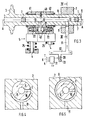
- a first middle cam designed as a switching cam 14 is rotatably mounted on the camshaft 1, while on both sides a second or third cam designed as a fixed cam 15 or 16 is arranged in a rotationally fixed manner.
- the switching cam 14 has in the area of its maximum elevation a through hole 17 in which a piston 18 is axially displaceably mounted.
- Both fixed cams 15, 16 have bores 19, 20 corresponding to the through bore 17.
- the radial bore 12 opens into bore 19 and a further, displaceable piston 21 is supported in it.
- Bore 20 has a spring-loaded hollow piston 22, the spring 23 of which is supported on a bottom 24 of the bore 20.
- the bores 19 and 20 and the through bore 17 are at the same distance H from the longitudinal axis AA of the camshaft 1 and the pistons 18, 21 and the hollow piston 22 have an identical diameter D.
- the maximum stroke of the fixed cams 15, 16 is less than that of the switching cam 14.
- Each valve 4 is assigned a conventional valve spring 25 and a hydraulic valve lash compensation element 26 integrated in the tappet 5.
- a check valve 29 is arranged in the pressure oil line 11 and is opened or blocked by an electronic control 31 via a line 30.
- This control 31 takes, inter alia, Signals corresponding to the current values of the oil temperature T and the engine speed N.
- the pressure oil line 11 is connected to a distributor line 32, which is connected to all cylinders of the internal combustion engine via further pressure oil lines 11 and is fed with pressure oil via an inlet 33.
- the shut-off valve 29 In the part-load operation of the internal combustion engine, the shut-off valve 29 is closed, and there is no oil pressure in the hydraulic chamber 13. Because of this, the spring 23 of the hollow piston 22 pushes the pistons 18 and 21 completely into the associated switching cam 14 or fixed cam 15. The switching cam 14 is decoupled and the camshaft 1 rotates freely in this cam 14. The fixed cams 15 and 16 run synchronously on the plunger 5 and actuate the inlet valves 4 with a relatively small stroke. When a certain load state of the internal combustion engine is exceeded, the shut-off valve 29 is opened and the annular groove 9 is continuously fed from the pressure oil line 11 via the bore 10. The oil pressure acting on the piston 21 pushes it against the switching cam 14.
- the switching cam is only coupled via a fixed cam 15 by means of the piston 21.
- the plunger 5 is designed as a roller plunger and is not explained in detail here, since it is described in DE-40 39 256 A1.
- the middle cam is provided for the part-load range of the internal combustion engine with a different profile than the fixed cams 15, 16 and actuates the plunger 5 with low friction via a roller 35, with the check valve 29 being open. All cams have an identical stroke.
- this embodiment corresponds to that shown in FIG.
- a third embodiment of the invention according to FIG. 3 has a central cam designed as a fixed cam 40 and on both sides thereof a cam designed as a switching cam 41 or 42.
- the radial bore 12 extends centrally in the fixed cam 40 and opens centrally into the hydraulic chamber 13 formed between two opposed pistons 43 and the through bore 19.
- the switching cams 41 and 42 each have a spring-loaded hollow piston 22.
- groove 9 is formed in the shape of a segment of a circle and all cylinders are assigned only one common check valve 29 in inlet 33.
- the middle cam is provided with a smaller stroke and assigned to the part-load range, while with increased load and open shut-off valve 29, the switching cams 41, 42, which are coupled with a larger stroke, actuate the plunger 5 in a form-fitting manner.
- both switching cams 41, 42 have an entry ramp 34.
- the controller 31 additionally processes a signal corresponding to the current throttle valve angle K.
- the switching cams are coupled or uncoupled at least as a function of the engine speed N.
- other parameters such as the throttle valve angle K
- the controller 31 can also be designed adaptively. In this case, according to FIG. 1, for example, a signal about the change in the throttle valve angle K over time is recorded as a measure of the dynamics of the driving operation of a motor vehicle equipped with this valve drive via a further input 43.
- a consciously calm driving style without dynamic jumps shifts the switching of the cams equipped with a larger stroke into the economic speed ranges of the internal combustion engine.
- shifting is shifted to areas that deliver optimum values for power and torque.
- a manually operated switch 44 can be provided, which allows a switchover between an economical and a sporty driving style in accordance with defined characteristic diagrams stored in the controller 31. Values for switching the switching cams as a function of the speed N are read from these characteristic maps.
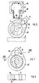
- a hydraulically operated locking device 45 with a piston 46 is used to fix the uncoupled switching cams 14 and 41, 42. 6, this is guided in a housing 47 held in the cylinder head and is passed via a pressure line 48 when the switching cam 14; 41, 42 extended. A defined position is thus given when the pistons are retracted into the inlet ramp 34 and there is a sufficiently long period of time for positive connection. The position is chosen so that the switching cam runs with its green circle 49 on the plunger 5 during connection.
Landscapes
- Engineering & Computer Science (AREA)
- Mechanical Engineering (AREA)
- General Engineering & Computer Science (AREA)
- Valve Device For Special Equipments (AREA)
- Valve-Gear Or Valve Arrangements (AREA)
Applications Claiming Priority (2)
| Application Number | Priority Date | Filing Date | Title |
|---|---|---|---|
| DE4228796 | 1992-08-29 | ||
| DE4228796A DE4228796A1 (de) | 1992-08-29 | 1992-08-29 | Ventilantriebsanordnung für eine Brennkraftmaschine |
Publications (2)
| Publication Number | Publication Date |
|---|---|
| EP0585568A1 true EP0585568A1 (fr) | 1994-03-09 |
| EP0585568B1 EP0585568B1 (fr) | 1995-12-06 |
Family
ID=6466728
Family Applications (1)
| Application Number | Title | Priority Date | Filing Date |
|---|---|---|---|
| EP93110921A Expired - Lifetime EP0585568B1 (fr) | 1992-08-29 | 1993-07-08 | Dispositif d'entrainement de soupape pour un moteur à combustion interne |
Country Status (5)
| Country | Link |
|---|---|
| US (1) | US5345898A (fr) |
| EP (1) | EP0585568B1 (fr) |
| JP (1) | JPH06200713A (fr) |
| KR (1) | KR940004177A (fr) |
| DE (2) | DE4228796A1 (fr) |
Cited By (5)
| Publication number | Priority date | Publication date | Assignee | Title |
|---|---|---|---|---|
| CN106545380A (zh) * | 2016-12-13 | 2017-03-29 | 大连理工大学 | 一种锁定式多模式杠杆式可变气门驱动系统 |
| CN106640253A (zh) * | 2016-12-13 | 2017-05-10 | 大连理工大学 | 一种集约型锁定式多模式液压可变气门驱动系统 |
| CN106640251A (zh) * | 2016-12-13 | 2017-05-10 | 大连理工大学 | 一种集约型锁定式多模式可变气门驱动系统 |
| CN106762011A (zh) * | 2016-12-13 | 2017-05-31 | 大连理工大学 | 一种紧凑型多模式可变气门驱动系统 |
| CN106837466A (zh) * | 2016-12-13 | 2017-06-13 | 大连理工大学 | 一种集约型锁定式多模式四杆式可变气门驱动系统 |
Families Citing this family (15)
| Publication number | Priority date | Publication date | Assignee | Title |
|---|---|---|---|---|
| DE4406968A1 (de) * | 1993-03-15 | 1994-09-22 | Volkswagen Ag | Nockenwellenanordnung mit einem auf einer Nockenwelle begrenzt schwenkbar gelagerten Schwenknocken |
| US5520144A (en) * | 1995-08-21 | 1996-05-28 | General Motors Corporation | Valve actuation assembly |
| JP2924777B2 (ja) * | 1996-04-08 | 1999-07-26 | トヨタ自動車株式会社 | 内燃機関のバルブタイミング可変機構 |
| DE19702389B4 (de) * | 1997-01-24 | 2004-05-27 | Audi Ag | Ventiltrieb für eine Brennkraftmaschine |
| JP4396024B2 (ja) * | 2000-03-13 | 2010-01-13 | マツダ株式会社 | シリンダヘッド構造 |
| US6871622B2 (en) | 2002-10-18 | 2005-03-29 | Maclean-Fogg Company | Leakdown plunger |
| US7028654B2 (en) | 2002-10-18 | 2006-04-18 | The Maclean-Fogg Company | Metering socket |
| US7128034B2 (en) | 2002-10-18 | 2006-10-31 | Maclean-Fogg Company | Valve lifter body |
| US7273026B2 (en) | 2002-10-18 | 2007-09-25 | Maclean-Fogg Company | Roller follower body |
| US7191745B2 (en) | 2002-10-18 | 2007-03-20 | Maclean-Fogg Company | Valve operating assembly |
| DE102006012385B3 (de) * | 2006-03-15 | 2007-10-11 | Iav Gmbh Ingenieurgesellschaft Auto Und Verkehr | Ventiltriebsanordnung für eine Brennkraftmaschine |
| DE102006012386B3 (de) * | 2006-03-15 | 2007-08-30 | Iav Gmbh Ingenieurgesellschaft Auto Und Verkehr | Ventiltrieb für eine Brennkraftmaschine |
| DE102008035935A1 (de) * | 2008-07-31 | 2010-02-11 | Audi Ag | Zahnwellenverbindung und Ventiltrieb mit Zahnwellenverbindung zwischen einer Nockenwelle und verschiebbaren Nockenträgern |
| EP2479388B1 (fr) * | 2009-09-14 | 2014-07-09 | Honda Motor Co., Ltd. | Commande variable des soupapes pour moteur à combustion interne |
| KR101209733B1 (ko) * | 2010-09-01 | 2012-12-07 | 현대자동차주식회사 | 가변 밸브 리프트 장치 |
Citations (4)
| Publication number | Priority date | Publication date | Assignee | Title |
|---|---|---|---|---|
| JPS62131907A (ja) * | 1985-12-04 | 1987-06-15 | Mazda Motor Corp | エンジンのバルブ駆動装置 |
| DE3732687A1 (de) * | 1986-10-07 | 1988-04-14 | Volkswagen Ag | Steuervorrichtung fuer die ladungswechselventile einer brennkraftmaschine |
| US4886022A (en) * | 1988-01-06 | 1989-12-12 | Mazda Motor Corporation | Engine valve driving apparatus |
| JPH0347416A (ja) * | 1989-07-14 | 1991-02-28 | Mitsubishi Motors Corp | バルブタイミング可変装置 |
Family Cites Families (11)
| Publication number | Priority date | Publication date | Assignee | Title |
|---|---|---|---|---|
| US4658780A (en) * | 1981-05-08 | 1987-04-21 | Yamaha Hatsudoki Kabushiki Kaisha | Four cycle internal combustion engine |
| JPS6341610A (ja) * | 1986-08-08 | 1988-02-22 | Mazda Motor Corp | エンジンのバルブ駆動装置 |
| JPH081125B2 (ja) * | 1986-10-16 | 1996-01-10 | マツダ株式会社 | エンジンのバルブ駆動装置 |
| JPH01138309A (ja) * | 1987-11-24 | 1989-05-31 | Mazda Motor Corp | エンジンの動弁装置 |
| JPH01208505A (ja) * | 1988-02-12 | 1989-08-22 | Mazda Motor Corp | エンジンのバルプ駆動装置 |
| JPH068604B2 (ja) * | 1988-05-23 | 1994-02-02 | 本田技研工業株式会社 | 内燃機関の弁作動状態切換装置 |
| US4934860A (en) * | 1988-07-13 | 1990-06-19 | Honeywell Inc. | Pivotal shaft frictionless support arrangement |
| JPH0747923B2 (ja) * | 1989-06-30 | 1995-05-24 | いすゞ自動車株式会社 | 可変バルブタイミング・リフト装置 |
| US5253621A (en) * | 1992-08-14 | 1993-10-19 | Group Lotus Plc | Valve control means |
| DE4014401C1 (fr) * | 1990-05-04 | 1991-03-21 | Dr.Ing.H.C. F. Porsche Ag, 7000 Stuttgart, De | |
| DE4039256C2 (de) * | 1990-12-08 | 1996-05-09 | Schaeffler Waelzlager Kg | Einrichtung zur gleichzeitigen Betätigung zweier Gaswechselventile einer Brennkraftmaschine |
-
1992
- 1992-08-29 DE DE4228796A patent/DE4228796A1/de not_active Ceased
-
1993
- 1993-07-08 EP EP93110921A patent/EP0585568B1/fr not_active Expired - Lifetime
- 1993-07-08 DE DE59301091T patent/DE59301091D1/de not_active Expired - Fee Related
- 1993-08-26 JP JP21187893A patent/JPH06200713A/ja not_active Withdrawn
- 1993-08-27 US US08/112,328 patent/US5345898A/en not_active Expired - Fee Related
- 1993-08-28 KR KR1019930016901A patent/KR940004177A/ko not_active Withdrawn
Patent Citations (4)
| Publication number | Priority date | Publication date | Assignee | Title |
|---|---|---|---|---|
| JPS62131907A (ja) * | 1985-12-04 | 1987-06-15 | Mazda Motor Corp | エンジンのバルブ駆動装置 |
| DE3732687A1 (de) * | 1986-10-07 | 1988-04-14 | Volkswagen Ag | Steuervorrichtung fuer die ladungswechselventile einer brennkraftmaschine |
| US4886022A (en) * | 1988-01-06 | 1989-12-12 | Mazda Motor Corporation | Engine valve driving apparatus |
| JPH0347416A (ja) * | 1989-07-14 | 1991-02-28 | Mitsubishi Motors Corp | バルブタイミング可変装置 |
Non-Patent Citations (2)
| Title |
|---|
| PATENT ABSTRACTS OF JAPAN vol. 11, no. 352 (M - 643)<2799> 18 November 1987 (1987-11-18) * |
| PATENT ABSTRACTS OF JAPAN vol. 15, no. 19052 (M - 113) 16 May 1991 (1991-05-16) * |
Cited By (8)
| Publication number | Priority date | Publication date | Assignee | Title |
|---|---|---|---|---|
| CN106545380A (zh) * | 2016-12-13 | 2017-03-29 | 大连理工大学 | 一种锁定式多模式杠杆式可变气门驱动系统 |
| CN106640253A (zh) * | 2016-12-13 | 2017-05-10 | 大连理工大学 | 一种集约型锁定式多模式液压可变气门驱动系统 |
| CN106640251A (zh) * | 2016-12-13 | 2017-05-10 | 大连理工大学 | 一种集约型锁定式多模式可变气门驱动系统 |
| CN106762011A (zh) * | 2016-12-13 | 2017-05-31 | 大连理工大学 | 一种紧凑型多模式可变气门驱动系统 |
| CN106837466A (zh) * | 2016-12-13 | 2017-06-13 | 大连理工大学 | 一种集约型锁定式多模式四杆式可变气门驱动系统 |
| CN106545380B (zh) * | 2016-12-13 | 2018-10-19 | 大连理工大学 | 一种锁定式多模式杠杆式可变气门驱动系统 |
| CN106837466B (zh) * | 2016-12-13 | 2018-12-21 | 大连理工大学 | 一种集约型锁定式多模式四杆式可变气门驱动系统 |
| CN106640253B (zh) * | 2016-12-13 | 2018-12-25 | 大连理工大学 | 一种集约型锁定式多模式液压可变气门驱动系统 |
Also Published As
| Publication number | Publication date |
|---|---|
| JPH06200713A (ja) | 1994-07-19 |
| DE4228796A1 (de) | 1994-03-03 |
| KR940004177A (ko) | 1994-03-14 |
| US5345898A (en) | 1994-09-13 |
| DE59301091D1 (de) | 1996-01-18 |
| EP0585568B1 (fr) | 1995-12-06 |
Similar Documents
| Publication | Publication Date | Title |
|---|---|---|
| EP0585568B1 (fr) | Dispositif d'entrainement de soupape pour un moteur à combustion interne | |
| DE4024057C1 (fr) | ||
| EP1608849B1 (fr) | Commande de soupape d'un moteur a combustion interne presentant une culasse | |
| DE4322480C2 (de) | Vorrichtung zur variablen Ventilsteuerung von Brennkraftmaschinen | |
| EP2315920B1 (fr) | Liaison par cannelures et mécanisme de distribution avec liaison par cannelures entre un arbre à cames et des supports de came déplaçables | |
| DE102007002802B4 (de) | Verfahren zum Umstellen eines Ventiltriebs einer Brennkraftmaschine zwischen einem Zweitakt- und einem Viertaktbetrieb und Ventiltrieb | |
| EP0595060B1 (fr) | Commande de soupape pour moteur à combustion interne | |
| EP0469334B1 (fr) | Procédé pour changer la position angulaire des arbres d'un moteur à combustion interne | |
| DE19851045B4 (de) | Variable Ventilbetätigungsvorrichtung | |
| DE3782035T2 (de) | Ventilantriebmechanismus fuer brennkraftmaschine. | |
| DE68904693T2 (de) | Vorrichtung zum umschalten der betriebsart der ventile in einer brennkraftmaschine. | |
| DE69405555T2 (de) | Ventilsteueranordnung | |
| DE19548389A1 (de) | Verstellvorrichtung für den Hubverlauf eines Gaswechselventils einer Brennkraftmaschine | |
| EP1216345B1 (fr) | Moteur a combustion interne equipe d'un dispositif hydraulique de reglage d'arbre a cames | |
| DE10148179B4 (de) | Ventiltrieb mit Ventilhubumschaltung für die Gaswechselventile eines 4-Takt-Verbrennungsmotors | |
| EP0538508A1 (fr) | Alimentation en huile sous pression pour la commande variable des soupapes d'un moteur à combustion interne | |
| EP0500622B1 (fr) | Dispositif d'entrainement pour un arbre a cames loge dans la culasse d'un moteur a combustion interne | |
| EP0518898B1 (fr) | Dispositif d'entrainement d'arbre a came | |
| DE4117006C2 (fr) | ||
| DE102005013402A1 (de) | Vorrichtung zur Veränderung der Steuerzeiten einer Brennkraftmaschine | |
| EP0624717B1 (fr) | Moteur à combustion interne avec dispositif de déphasage de l'entraînement des arbres à cames | |
| DE3732687C2 (fr) | ||
| DE4229201C2 (de) | Vorrichtung zum Verstellen der Nockenwellen-Steuerzeiten | |
| EP0845582A1 (fr) | Commande de soupape pour un moteur à combustion interne équipé de soupapes à levée pour le transfert de charge | |
| DE4230809C2 (de) | Ventilsteuerung für Brennkraftmaschinen |
Legal Events
| Date | Code | Title | Description |
|---|---|---|---|
| PUAI | Public reference made under article 153(3) epc to a published international application that has entered the european phase |
Free format text: ORIGINAL CODE: 0009012 |
|
| AK | Designated contracting states |
Kind code of ref document: A1 Designated state(s): DE FR GB IT |
|
| 17P | Request for examination filed |
Effective date: 19940824 |
|
| 17Q | First examination report despatched |
Effective date: 19950517 |
|
| GRAA | (expected) grant |
Free format text: ORIGINAL CODE: 0009210 |
|
| ITF | It: translation for a ep patent filed | ||
| AK | Designated contracting states |
Kind code of ref document: B1 Designated state(s): DE FR GB IT |
|
| REF | Corresponds to: |
Ref document number: 59301091 Country of ref document: DE Date of ref document: 19960118 |
|
| GBT | Gb: translation of ep patent filed (gb section 77(6)(a)/1977) |
Effective date: 19960124 |
|
| ET | Fr: translation filed | ||
| PGFP | Annual fee paid to national office [announced via postgrant information from national office to epo] |
Ref country code: FR Payment date: 19960729 Year of fee payment: 4 |
|
| PGFP | Annual fee paid to national office [announced via postgrant information from national office to epo] |
Ref country code: DE Payment date: 19960819 Year of fee payment: 4 |
|
| PLBE | No opposition filed within time limit |
Free format text: ORIGINAL CODE: 0009261 |
|
| STAA | Information on the status of an ep patent application or granted ep patent |
Free format text: STATUS: NO OPPOSITION FILED WITHIN TIME LIMIT |
|
| 26N | No opposition filed | ||
| PG25 | Lapsed in a contracting state [announced via postgrant information from national office to epo] |
Ref country code: GB Free format text: LAPSE BECAUSE OF NON-PAYMENT OF DUE FEES Effective date: 19970708 |
|
| GBPC | Gb: european patent ceased through non-payment of renewal fee |
Effective date: 19970708 |
|
| PG25 | Lapsed in a contracting state [announced via postgrant information from national office to epo] |
Ref country code: FR Free format text: LAPSE BECAUSE OF NON-PAYMENT OF DUE FEES Effective date: 19980331 |
|
| PG25 | Lapsed in a contracting state [announced via postgrant information from national office to epo] |
Ref country code: DE Free format text: LAPSE BECAUSE OF NON-PAYMENT OF DUE FEES Effective date: 19980401 |
|
| REG | Reference to a national code |
Ref country code: FR Ref legal event code: ST |
|
| PG25 | Lapsed in a contracting state [announced via postgrant information from national office to epo] |
Ref country code: IT Free format text: LAPSE BECAUSE OF NON-PAYMENT OF DUE FEES;WARNING: LAPSES OF ITALIAN PATENTS WITH EFFECTIVE DATE BEFORE 2007 MAY HAVE OCCURRED AT ANY TIME BEFORE 2007. THE CORRECT EFFECTIVE DATE MAY BE DIFFERENT FROM THE ONE RECORDED. Effective date: 20050708 |