EP0585638A1 - Filtre optique passe-bas comprenant un réseau de phase sélectif en longeur d'onde muni de couche d'adhésion entre des couches transparantes - Google Patents
Filtre optique passe-bas comprenant un réseau de phase sélectif en longeur d'onde muni de couche d'adhésion entre des couches transparantes Download PDFInfo
- Publication number
- EP0585638A1 EP0585638A1 EP93112459A EP93112459A EP0585638A1 EP 0585638 A1 EP0585638 A1 EP 0585638A1 EP 93112459 A EP93112459 A EP 93112459A EP 93112459 A EP93112459 A EP 93112459A EP 0585638 A1 EP0585638 A1 EP 0585638A1
- Authority
- EP
- European Patent Office
- Prior art keywords
- wavelength
- pass filter
- optical low
- transparent layers
- phase
- Prior art date
- Legal status (The legal status is an assumption and is not a legal conclusion. Google has not performed a legal analysis and makes no representation as to the accuracy of the status listed.)
- Granted
Links
Images


Classifications
-
- G—PHYSICS
- G02—OPTICS
- G02B—OPTICAL ELEMENTS, SYSTEMS OR APPARATUS
- G02B27/00—Optical systems or apparatus not provided for by any of the groups G02B1/00 - G02B26/00, G02B30/00
- G02B27/42—Diffraction optics, i.e. systems including a diffractive element being designed for providing a diffractive effect
- G02B27/46—Systems using spatial filters
-
- G—PHYSICS
- G02—OPTICS
- G02B—OPTICAL ELEMENTS, SYSTEMS OR APPARATUS
- G02B5/00—Optical elements other than lenses
- G02B5/18—Diffraction gratings
- G02B5/1866—Transmission gratings characterised by their structure, e.g. step profile, contours of substrate or grooves, pitch variations, materials
- G02B5/1871—Transmissive phase gratings
Definitions
- the present invention relates to a wavelength-selective phase grating type optical low-pass filter, more particularly, to a wavelength-selective phase grating type optical low-pass filter comprising an adhesive layer between a pair of transparent layers, for use in an optical system such as a single-tube color video camera or a color video camera employing a solid-state image sensor having a color separation filter.
- an image of a subject focused on the CCD image sensor is spatially and discretely sampled to obtain output image data, with a predetermined sampling frequency equal to a Nyquist frequency of the CCD image sensor.
- the output image data generated by the solid-state CCD image sensor contains data of a configuration or phantom data which are not included in the subject data.
- such frequency components higher than the Nyquist frequency which can not be picked up by the solid-state CCD image sensor are outputted in a form of phantom data such as aliasing components, Moire, and phantom color.
- the optical low-pass filter has been made utilizing a crystal plate having a birefringence characteristic or recently utilizing a phase grating.
- almost all the conventional optical low-pass filters have been intended for obtaining a low-pass effect generally equal over the whole wavelengths.
- the following technique attempt has been put into practice taking advantage of the fact that the spatial distribution densities of respective color separation filters, i.e., the spatial frequencies thereof are different from each other in respective transmission wavelength bands.
- the technique is that an image signal in a wavelength band having a distribution of higher spatial frequencies is subjected to sampling at a relatively higher sampling frequency, while another image signal in a wavelength band having a distribution of lower spatial frequencies is subjected to sampling at a relatively lower sampling frequency, thereby obtaining appropriate image data.
- a conventional optical low-pass filter comprising a pair of adjacent transparent layers adhering to each other has been suggested in the Japanese patent laid-open publication No. 3-230156, wherein refractive indexes of adjacent transparent layers at a wavelength are the same as each other, and the adjacent transparent layers of materials have Abbe's numbers different from each other, thereby attenuating a particular wavelength component.
- refractive indexes of adjacent transparent layers at a wavelength are the same as each other, and the adjacent transparent layers of materials have Abbe's numbers different from each other, thereby attenuating a particular wavelength component.
- the adhesive layer becomes a phase grating layer, and then there is a possibility of not obtaining a desirable low-pass effect.
- An object of the present invention is therefore to provide a wavelength-selective phase grating type optical low-pass filter capable of not attenuating an MTF value of green or having a higher MTF value of green, even though an adhesive layer is inserted between a pair of transparent layers.
- Another object of the present invention is to provide a wavelength-selective phase grating type optical low-pass filter capable of having an improved high resolution in visual characteristics, even though an adhesive layer is inserted between a pair of transparent layers.
- a wavelength-selective phase-grating type optical low-pass filter comprising: at least a pair of adjacent first and second transparent layers; and at least one adhesive layer through which said pair of adjacent first and second transparent layers stacked on each other in a phase grating form for generating a phase difference distribution on the boundary surface between said pair of adjacent first and second transparent layers, wherein said optical low-pass filter satisfies the following conditions under a condition of 470 nm ⁇ ⁇ ⁇ 580 nm:
- each of respective boundary surfaces of said first and second transparent layers has a cross section having such a shape that a plurality of trapezoids are periodically formed in a predetermined direction so that the respective boundary surfaces thereof are parallel to each other.
- phase grating form satisfies the following conditions:
- the above-mentioned wavelength-selective phase-grating type optical low-pass filter preferably further comprises: a third transparent layer; and a further adhesive layer through which said second and third transparent layers stacked on each other in a further phase grating form for generating a further phase difference distribution on the boundary surface between said second and third transparent layers, said further phase grating form being perpendicular to said phase grating form.
- the attenuation of the MTF value in the wavelength band of green can be prevented, namely, the cut-off spatial frequency of the wavelength band of green can be set to a spatial frequency higher than those of the wavelength bands of red and blue. This results in improvement in the resolution or a higher resolution in the visual characteristics.
- Fig. 1 shows an arrangement of an optical system comprising a wavelength-selective phase-grating type optical low-pass filter of a preferred embodiment according to the present invention.
- reference numeral 1 denotes a subject, an image of which (referred to as a subject image hereinafter) is to be picked up
- reference numeral 2 denotes a lens system comprising at least one lens
- Reference numeral 3 denotes a wavelength-selective phase-grating type optical low-pass filter according to the present invention, which is disposed between the lens system 2 and a color separation filter 4.
- reference numeral 5 denotes an image forming surface located on a CCD image sensor 6 on which the subject image is formed through the lens system 2, the optical low-pass filter 3 and the color separation filter 4.
- low-pass effects are obtained at respective wavelengths by arranging the optical low-pass filter 3 between the CCD image sensor 6 and the subject 1, as shown in Fig. 1.
- the position of the optical low-pass filter 3 is not limited to this, and the optical low-pass filter 3 may be provided at either a position within the lens system 2 or another position between the subject 1 and the lens system 2.
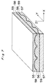
- Fig. 2a shows the wavelength-selective phase-grating type optical low-pass filter 3 shown in Fig. 1, and Fig. 2b shows a cross section thereof.
- the optical low-pass filter 3 comprises a pair of adjacent transparent layers 7 and 8 each made of glass, and an adhesive layer 9 of an adhesive agent of ultraviolet rays hardening resin, which is inserted between the transparent layers 7 and 8, wherein the transparent layer 7 is located on the side of the subject 1, and another transparent layer 8 is located on the side of the CCD image sensor 6. Further, the transparent layers 7 and 8 are provided for forming a phase difference shape for generating a phase difference distribution, or a phase grating shape.
- the light reflected from the subject 1 is incident onto the top surface of the transparent layer 7, and passes through the transparent layer 7, the adhesive layer 9 and the transparent layer 8. Finally, the reflected light is outputted from the bottom surface of the transparent layer 9, toward an CCD image sensor (not shown).
- each of respective boundary surfaces of a pair of transparent layers 7 and 8 has a cross section having such a shape that a plurality of trapezoids are periodically formed in a direction parallel to the X-axis direction so that the respective boundary surfaces thereof are parallel to each other. It is to be noted that, when cutting the optical low-pass filter 3 at respective points along the Y-axis direction in parallel to a ZX surface, respective cross sections are the same as each other, as shown in Fig. 2a.
- each trapezoid has a width of "a”, and a bottom flat portion thereof has a width of "b”, and a period length or pitch of each trapezoid in the phase grating is represented by "A”. Further, each trapezoid has a height of "h”, and "D” denotes the thickness of the optical low-pass filter 3.
- the following equations (1) to (3) are preferably satisfied for an optimum condition for designing the optical low-pass filter 3: where f is a cut-off spatial frequency or so- called Nyquist frequency to be set so as to prevent generation of Moire, phantom signal or the like; ⁇ R is the center wavelength of red (R) band; ⁇ B is the center wavelength of blue (B) band; d is a distance between the optical low-pass filter 3 and the image forming surface 5 of the CCD image sensor 6; NR is a difference between the refractive indexes of a pair of adjacent transparent layers 7 and 8 at the center wavelength ⁇ R of red (R) band; and NB is a difference between the refractive indexes between a pair of adjacent transparent layers 7 and 8 at the center wavelength ⁇ B of blue (B) band.
- the refractive indexes of the adjacent transparent layers 7 and 8 and the dispersions thereof are preferably set as follows. Under such a condition of the wavelength ⁇ in a range of 470 nm ⁇ ⁇ ⁇ 580 nm, namely, in the range within a wavelength band of green of the primary color of the color filter, the materials of glass of a pair of adjacent transparent layers 7 and 8 are preferably selected so as to satisfy the following conditions:
- the low-pass effect due to the optical low-pass filter 3 is relatively small, and then the MTF characteristic of green extends up to a higher spatial frequency. That is, the MTF value of green does not attenuate up to the higher spatial frequency.
- the low-pass effect due to the optical low-pass filter 3 becomes relatively large, and then the MTF characteristic is cut off at a relatively lower spatial frequency. This results in improvement in the resolution or an improved higher resolution in the visual characteristics.
- the parameters of the optical low-pass filter 3 are set so that the cut-off spatial frequency of green is set as high as possible and the cut-off spatial frequency of red or blue is set to a spatial frequency close to that of the conventional optical low-pass filter.
- the adhesive layer 9 inserted between a pair of adjacent transparent layers 7 and 8 has a relatively large thickness or a distribution of the thickness thereof, it is necessary to set the shape of the materials of a pair of transparent layers 7 and 8 and the refractive indexes thereof to a desirable shape and desirable values, respectively, and further it is necessary to set the refractive index of the adhesive layer 9 to a desirable value so as to obtain the above-mentioned low-pass effects.
- the parameters "a”, "b” and A are preferably set to satisfy the following equations (4): 0.1 ⁇ a/A ⁇ 0.9, 0.1 ⁇ a/B ⁇ 0.9, and (a + b)/A ⁇ 1.0 (4)
- equations (4) 0.1 ⁇ a/A ⁇ 0.9, 0.1 ⁇ a/B ⁇ 0.9, and (a + b)/A ⁇ 1.0 (4)
- the OTF (Optical Transfer Function) characteristic which is obtained by adding phase data to MTF is represented by the following equation (5):
- n1 is a refractive index of the transparent layer 7
- n2 is a refractive index of the transparent layer 8
- the above equation (5) is represented by the following equation (6):
- the OTFs in respect of the primary colors of red (R) and blue (B) are obtained as follows:
- Fig. 3 is a graph of a MTF value to spatial frequency characteristics of the wavelength-selective phase-grating type optical low-pass filter shown in Figs. 2a and 2b, showing characteristic curves 12, 13 and 14 thereof, respectively, at respective wavelength bands of blue, red and green.
- fcR is a cut-off spatial frequency within the wavelength band of red
- fcB is a cut-off spatial frequency within the wavelength band of blue.
- the optical low-pass filter 3 having the MTF value frequency characteristics shown in Fig. 3, the positional relationship between the optical low-pass filter 3 and the image forming surface 5 and the shape of the phase difference of the phase grating of the optical low-pass filter 3 are adjusted so that the cut-off spatial frequency of this optical system to be set so as to prevent generation of color Moire or phantom image due to the blue and red components of the color filter is set to a spatial frequency between the cut-off spatial frequencies fcB and fcR.
- the MTF value within the wavelength band of green at the cut-off spatial frequency of this system becomes sufficiently high, while the MTF value within the wavelength band of red or blue at the cut-off spatial frequency of this optical system becomes sufficiently low. This results in that the red and blue components can not be detected at the higher spatial frequencies.
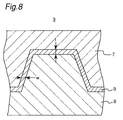
- Fig. 8 is an enlarged schematic cross sectional view of the wavelength-selective phase-grating type optical low-pass filter 3 shown in Figs. 2a and 2b, showing a thickness "t" in the vertical direction of the adhesive layer 9 and a width "w" in the horizontal direction thereof.
- Fig. 9 is a graph of MTF value to spatial frequency characteristics in the wavelength band of red, with a parameter of a ratio Np( ⁇ ) / No( ⁇ ) of a refractive index Np( ⁇ ) of the adhesive layer 9 to a refractive index No( ⁇ ) of the transparent layer 7, which is changed in a range from 0.9 to 1.1, wherein ⁇ is set to a wavelength in a range from 470 nm to 580 nm.
- Fig. 10 is a graph of MTF value to spatial frequency characteristics in the wavelength band of blue, with the parameter of the ratio Np( ⁇ ) / No( ⁇ ) which is changed in a range from 0.9 to 1.1.
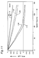
- Fig. 11 is a graph of MTF value to spatial frequency characteristics in the wavelength band of green, with the parameter of the ratio Np( ⁇ ) / No( ⁇ ) which is changed in a range from 0.9 to 1.1.
- each of the MTF values shown in Figs. 9 to 11 includes a sign representing a direction of the phase thereof.
- Fig. 5 shows an optical system for obtaining a doubled horizontal resolution, using the optical low-pass filter 3 of the preferred embodiment according to the present invention.
- the low-pass effects of the present invention is utilized in a horizontal direction, which is defined as a horizontal direction when seeing the front surface of the optical low-pass filter 2, while a vertical direction is defined as a vertical direction perpendicular to the horizontal direction on the surfaces of the optical low-pass filter 3.
- reference numeral 30 denotes a lens system.
- an optical low-pass filter 21 for limiting or attenuating the spatial frequency components which propagate at a spatial frequency equal to half the Nyquist frequency of a CCD image sensor 27, in order to take into consideration the sampling frequency of the CCD image sensor 27 with respect to the vertical direction perpendicular to the horizontal direction on the surfaces of the optical low-pass filter 3.
- the reason why the cut-off frequency is set to be half the Nyquist frequency is as follows.
- the limit of the CCD image sensor 27 for picking up an subject image in the case of no color filter or a monochrome state is defined as the Nyquist frequency.
- the optical low-pass filter 21 has only a sampling frequency equal to half the sampling frequency in the monochrome sate.
- the Nyquist frequency of the CCD image sensor 27 is preferably set as the cut-off spatial frequency required for the conventional low-pass filter.
- an optical low-pass filter 22 is provided.
- the optical low-pass filter 21 attenuates the spatial frequency components in the vertical direction higher than half the Nyquist frequency of the CCD image sensor 27. Further, the optical low-pass filter 22 attenuates the spatial frequency components in the horizontal direction higher than the Nyquist frequency of the CCD image sensor 27.
- an infrared radiation cut filter 23 for attenuating the frequency components of the infrared rays.
- the filters 21, 22, 23 and 3 are provided for constituting an optical filter system 28, in this order so that the optical low-pass filter 21 is located on the side of the lens system 30.
- the optical filter system 28 is located between the lens system 30 and a CCD image sensor unit 29.
- the order for arranging the filters 21, 22, 23 and 3 is not limited to this, and any order thereof may be set. Further, each of the filters 21, 22, 23 and 3 may be turned over.
- the filters 21, 22, 23 and 3 have respective above-mentioned functions, respectively. Further, the low-pass effects of the optical low-pass filters can be improved by combining each of the respective above filters 21, 22, 23 and 3 with a wave plate and an optical low-pass filter having a cut-off spatial frequency different from that of each of the respective above filters 21, 22, 23 and 3. It is required for these optical low-pass filters to set the MTF value of the optical system at a desirable cut-off spatial frequency to a sufficiently small value, and also to suppress or decrease the MTF value in the spatial frequency band higher than the cut-off spatial frequency of the present optical system.
- the MTF value increases at the spatial frequency slightly higher than the cut-off spatial frequency. Therefore, in order to reduce this influence, it is necessary to provide a sufficient low-pass characteristic at the cut-off spatial frequency, and further, it is necessary to decrease the MTF value in the spatial frequency band higher than the cut-off spatial frequency.
- the solid-state CCD image sensor unit 29 a protection glass 25, a color filter 26, and the CCD image sensor 27 for converting the subject image into electric signals using the sampling frequency equal to the Nyquist frequency.
- the optical low-pass filter 3 has only the above-mentioned low-pass effects in the horizontal direction. Further, since the green components of the image data are almost not influenced by the low-pass effects, it is necessary to provide not only the optical low-pass filter 21 for obtaining the low-pass effects in the vertical direction but also the optical low-pass filter 22 for obtaining the low-pass effects in the horizontal direction in order to attenuate the green components.
- Fig. 6 shows an image processing system of a video camera of the preferred embodiment, comprising the wavelength-selective phase-grating type optical low-pass filter 3 shown in Figs. 2a and 2b.
- the image sensor unit 29 converts the received subject image into sampled electric image signals, and outputs the sampled electric image signals through a sample hold circuit 40, an automatic gain control (AGC) amplifier 41, and a ⁇ -correction circuit 42, to a signal processing circuit 43.
- AGC automatic gain control
- the signal processing circuit 43 makes luminance signals and color signals of red, green and blue, respectively corresponding to the red, green and blue wavelength bands for which a predetermined low-pass filtering and a predetermined white balance process have been effected, then generates an FM signal including the above-mentioned luminance signals and the color signals, namely, the FM signal obtained by frequency-modulating a predetermined carrier wave according to the luminance signals and the color signals, and outputs the FM signal through a wide band amplifier 44 to a magnetic head 45 for recording the FM signal onto a magnetic tape.
- the optical filter system 28 comprises the optical low-pass filter 3 of the present invention
- the weight of the luminance signal of green becomes relatively large among all the luminance signals, and the cut-off spatial frequency of the wavelength band of green can be set to a spatial frequency higher than those of the wavelength bands of red and blue. This results in a higher resolution in the visual characteristics as compared with the conventional optical low-pass filters.
- each of respective boundary surfaces of a pair of transparent layers 7 and 8 has a cross section having such a shape that a plurality of trapezoids are periodically formed in the X-axis direction so that the respective boundary surfaces thereof are parallel to each other.
- the present invention is not limited to this, the following modifications can be used.
- Fig. 4 is a schematic perspective view of a wavelength-selective phase-grating type optical low-pass filter of another preferred embodiment according to the present invention.
- the optical low-pass filter shown in Fig. 4 comprises three transparent layers 15, 16 and 17, an adhesive layer 18 inserted between the adjacent layers 15 and 16, and another adhesive layer 19 inserted between the adjacent layers 16 and 17.
- This structure of the optical low-pass filter comprises two adhesive layers 18 and 19, and then, in a manner similar to that of the above-mentioned preferred embodiment shown in Figs. 2a and 2b, each of respective boundary surfaces of a pair of transparent layers 15 and 16 has a cross section having such a shape that a plurality of trapezoids are periodically formed in the X-axis direction, while each of respective boundary surfaces of a pair of transparent layers 16 and 17 has a cross section having such a shape that a plurality of trapezoids are periodically formed in the Y-axis direction.
- a first phase difference is generated unidimensionally in the X-axis direction by the adhesive layer 18, while another second phase difference is generated unidimensionally in the Y-axis direction by another adhesive layer 19.
- respective cross sections are the same as each other.
- respective cross sections are the same as each other.
- the present optical low-pass filter since the first phase difference is generated in the X-axis direction while the second phase difference is generated in the Y-axis direction, the present optical low-pass filter has improvement in the resolution or a higher resolution in the visual characteristics in the two directions of the horizontal and vertical directions perpendicular to each other. In other words, the wavelength-selective low-pass effect can be obtained with respect to the entire part of a two-dimensional image.
- another optical low-pass filter comprises three transparent layers 55, 56 and 57, a first adhesive layer 58 inserted between the transparent layers 55 and 56, and a second adhesive layer 59 inserted between the transparent layers 56 and 57.
- On the cross section of an optical low-pass filter there are formed as boundary surfaces in each of the two adhesive layers 58 and 59, a plurality of half-ellipses in stead of a plurality of trapezoids.
- This optical low-pass filter has improvement in the resolution or a higher resolution in the visual characteristics in the two directions of the horizontal and vertical directions perpendicular to each other.
- the optical low-pass filter may comprises four or more transparent layers, between respective adjacent transparent layers of which an adhesive layer is inserted.
Landscapes
- Physics & Mathematics (AREA)
- General Physics & Mathematics (AREA)
- Optics & Photonics (AREA)
- Color Television Image Signal Generators (AREA)
Applications Claiming Priority (2)
| Application Number | Priority Date | Filing Date | Title |
|---|---|---|---|
| JP208715/92 | 1992-08-05 | ||
| JP4208715A JPH0659218A (ja) | 1992-08-05 | 1992-08-05 | 光学的ローパスフィルタ |
Publications (2)
| Publication Number | Publication Date |
|---|---|
| EP0585638A1 true EP0585638A1 (fr) | 1994-03-09 |
| EP0585638B1 EP0585638B1 (fr) | 1997-01-02 |
Family
ID=16560889
Family Applications (1)
| Application Number | Title | Priority Date | Filing Date |
|---|---|---|---|
| EP93112459A Expired - Lifetime EP0585638B1 (fr) | 1992-08-05 | 1993-08-04 | Filtre optique passe-bas comprenant un réseau de phase sélectif en longeur d'onde muni de couche d'adhésion entre des couches transparantes |
Country Status (4)
| Country | Link |
|---|---|
| US (1) | US5434709A (fr) |
| EP (1) | EP0585638B1 (fr) |
| JP (1) | JPH0659218A (fr) |
| DE (1) | DE69307055T2 (fr) |
Cited By (2)
| Publication number | Priority date | Publication date | Assignee | Title |
|---|---|---|---|---|
| EP0706067A1 (fr) * | 1994-09-07 | 1996-04-10 | Kureha Kagaku Kogyo Kabushiki Kaisha | Filtre optique plastique |
| US5672655A (en) * | 1994-09-13 | 1997-09-30 | Kureha Kagaku Kogyo Kabushiki Kaisha | Plastic optical material and production process thereof |
Families Citing this family (11)
| Publication number | Priority date | Publication date | Assignee | Title |
|---|---|---|---|---|
| US5781236A (en) * | 1994-03-04 | 1998-07-14 | Canon Kabushiki Kaisha | Image sensing apparatus and image sensing method |
| US6292212B1 (en) * | 1994-12-23 | 2001-09-18 | Eastman Kodak Company | Electronic color infrared camera |
| US6781756B1 (en) | 1995-08-29 | 2004-08-24 | Olympus Corporation | Diffractive optical element |
| US6157488A (en) * | 1995-08-29 | 2000-12-05 | Olympus Optical Company Ltd. | Diffractive optical element |
| US5734502A (en) * | 1996-02-07 | 1998-03-31 | Lexitek, Inc. | Achromatic diffractive optic |
| EP1014116A4 (fr) * | 1996-12-03 | 2001-10-24 | Kureha Chemical Ind Co Ltd | Reseau de phase et procede de fabrication |
| US6327085B1 (en) | 1998-03-31 | 2001-12-04 | Nikon Corporation | Optical filter and optical device provided with this optical filter |
| KR100390875B1 (ko) * | 1999-10-27 | 2003-07-10 | (주)해빛정보 | 위상 회절 격자형 광 저대역 통과필터 |
| US7167615B1 (en) | 1999-11-05 | 2007-01-23 | Board Of Regents, The University Of Texas System | Resonant waveguide-grating filters and sensors and methods for making and using same |
| US20110075256A1 (en) * | 2008-06-02 | 2011-03-31 | Koninklijke Philips Electronics N.V. | optical arrangement and an autostereoscopic display device incorporating the same |
| KR102200036B1 (ko) * | 2014-06-13 | 2021-01-07 | 쓰리엠 이노베이티브 프로퍼티즈 컴파니 | 스파클 감소용 광학 스택 |
Citations (4)
| Publication number | Priority date | Publication date | Assignee | Title |
|---|---|---|---|---|
| US4477148A (en) * | 1981-05-13 | 1984-10-16 | Canon Kabushiki Kaisha | Optical low-pass filter |
| EP0186166A1 (fr) * | 1984-12-25 | 1986-07-02 | Sony Corporation | Filtre optique passebas utilisant un réseau |
| EP0454409A1 (fr) * | 1990-04-27 | 1991-10-30 | Matsushita Electric Industrial Co., Ltd. | Filtre optique passe-bas utilisant un réseau de phase sélectif en longueur d'onde |
| EP0531926A1 (fr) * | 1991-09-10 | 1993-03-17 | Matsushita Electric Industrial Co., Ltd. | Filtre optique passe-bas utilisant un réseau de phase sélectif en longueur d'onde |
Family Cites Families (9)
| Publication number | Priority date | Publication date | Assignee | Title |
|---|---|---|---|---|
| JPS5222209B2 (fr) * | 1972-06-23 | 1977-06-16 | ||
| US4093346A (en) * | 1973-07-13 | 1978-06-06 | Minolta Camera Kabushiki Kaisha | Optical low pass filter |
| JPS53119063A (en) * | 1977-03-26 | 1978-10-18 | Minolta Camera Co Ltd | Optical low pass filter |
| US4484797A (en) * | 1981-07-20 | 1984-11-27 | Rca Corporation | Diffractive subtractive color filter responsive to angle of incidence of polychromatic illuminating light |
| JP2605703B2 (ja) * | 1986-12-24 | 1997-04-30 | ソニー株式会社 | 撮像装置 |
| JPS6472119A (en) * | 1987-09-11 | 1989-03-17 | Canon Kk | Optical low-pass filter |
| JPH07111514B2 (ja) * | 1988-04-04 | 1995-11-29 | 日本放送協会 | 光学的ローパスフイルタ |
| JPH0833527B2 (ja) * | 1988-07-18 | 1996-03-29 | キヤノン株式会社 | 光学的ローパスフィルターを有した撮影系 |
| JP2774168B2 (ja) * | 1989-12-20 | 1998-07-09 | オリンパス光学工業株式会社 | 位相格子部材 |
-
1992
- 1992-08-05 JP JP4208715A patent/JPH0659218A/ja active Pending
-
1993
- 1993-08-04 US US08/101,682 patent/US5434709A/en not_active Expired - Fee Related
- 1993-08-04 DE DE69307055T patent/DE69307055T2/de not_active Expired - Fee Related
- 1993-08-04 EP EP93112459A patent/EP0585638B1/fr not_active Expired - Lifetime
Patent Citations (4)
| Publication number | Priority date | Publication date | Assignee | Title |
|---|---|---|---|---|
| US4477148A (en) * | 1981-05-13 | 1984-10-16 | Canon Kabushiki Kaisha | Optical low-pass filter |
| EP0186166A1 (fr) * | 1984-12-25 | 1986-07-02 | Sony Corporation | Filtre optique passebas utilisant un réseau |
| EP0454409A1 (fr) * | 1990-04-27 | 1991-10-30 | Matsushita Electric Industrial Co., Ltd. | Filtre optique passe-bas utilisant un réseau de phase sélectif en longueur d'onde |
| EP0531926A1 (fr) * | 1991-09-10 | 1993-03-17 | Matsushita Electric Industrial Co., Ltd. | Filtre optique passe-bas utilisant un réseau de phase sélectif en longueur d'onde |
Cited By (2)
| Publication number | Priority date | Publication date | Assignee | Title |
|---|---|---|---|---|
| EP0706067A1 (fr) * | 1994-09-07 | 1996-04-10 | Kureha Kagaku Kogyo Kabushiki Kaisha | Filtre optique plastique |
| US5672655A (en) * | 1994-09-13 | 1997-09-30 | Kureha Kagaku Kogyo Kabushiki Kaisha | Plastic optical material and production process thereof |
Also Published As
| Publication number | Publication date |
|---|---|
| DE69307055D1 (de) | 1997-02-13 |
| JPH0659218A (ja) | 1994-03-04 |
| US5434709A (en) | 1995-07-18 |
| DE69307055T2 (de) | 1997-07-24 |
| EP0585638B1 (fr) | 1997-01-02 |
Similar Documents
| Publication | Publication Date | Title |
|---|---|---|
| EP0531926B1 (fr) | Filtre optique passe-bas utilisant un réseau de phase sélectif en longueur d'onde | |
| US5434709A (en) | Wavelength-selective phase grating type optical low-pass filter comprising adhesive layer between transparent layers | |
| US7110034B2 (en) | Image pickup apparatus containing light adjustment portion with reflection of a portion of light onto adjacent pixels | |
| US5280388A (en) | Wavelength selective phase grating optical low-pass filter | |
| US5589882A (en) | Integral infrared absorbing optical low-pass filter | |
| US4989959A (en) | Anti-aliasing optical system with pyramidal transparent structure | |
| KR100255908B1 (ko) | 촬영광학계 | |
| US6326998B1 (en) | Optical blur filter having a four-feature pattern | |
| EP1341235A2 (fr) | Appareil de prise d'images | |
| EP0584769B1 (fr) | Filtre passe-bas optique à deux dimensions | |
| JP3348460B2 (ja) | 撮像光学系 | |
| JPS5813891B2 (ja) | 光学的ロ−パスフィルタ− | |
| EP1109036A1 (fr) | Filtre passe-bas optique, bloc détecteur d'images et appareil utilisant ceux-ci | |
| JP2774168B2 (ja) | 位相格子部材 | |
| JPH10191160A (ja) | 画像形成装置 | |
| US4998801A (en) | Optical low-pass filter and photographic system using the same | |
| JP2615248B2 (ja) | 光学フイルタ | |
| JPH0483222A (ja) | カラー撮像装置 | |
| JP2001147404A (ja) | 光学ローパスフィルタ、それを有する撮像ユニット並びに撮像装置 | |
| JPS63307423A (ja) | 光学的ロ−パス効果を有した撮像素子 | |
| JPH01916A (ja) | 撮影レンズ | |
| JP2000206325A (ja) | 赤外線カットフィルタおよび赤外線カットフィルタを用いた撮像装置 | |
| JPH06175073A (ja) | 光学的ローパスフィルタ | |
| KR100312495B1 (ko) | 초박형회절광학렌즈 | |
| KR100427755B1 (ko) | 위상회절격자형 광 저대역 통과 필터 |
Legal Events
| Date | Code | Title | Description |
|---|---|---|---|
| PUAI | Public reference made under article 153(3) epc to a published international application that has entered the european phase |
Free format text: ORIGINAL CODE: 0009012 |
|
| 17P | Request for examination filed |
Effective date: 19930804 |
|
| AK | Designated contracting states |
Kind code of ref document: A1 Designated state(s): DE FR GB |
|
| 17Q | First examination report despatched |
Effective date: 19951102 |
|
| GRAG | Despatch of communication of intention to grant |
Free format text: ORIGINAL CODE: EPIDOS AGRA |
|
| GRAH | Despatch of communication of intention to grant a patent |
Free format text: ORIGINAL CODE: EPIDOS IGRA |
|
| GRAH | Despatch of communication of intention to grant a patent |
Free format text: ORIGINAL CODE: EPIDOS IGRA |
|
| GRAA | (expected) grant |
Free format text: ORIGINAL CODE: 0009210 |
|
| AK | Designated contracting states |
Kind code of ref document: B1 Designated state(s): DE FR GB |
|
| REF | Corresponds to: |
Ref document number: 69307055 Country of ref document: DE Date of ref document: 19970213 |
|
| ET | Fr: translation filed | ||
| PLBE | No opposition filed within time limit |
Free format text: ORIGINAL CODE: 0009261 |
|
| 26N | No opposition filed | ||
| PGFP | Annual fee paid to national office [announced via postgrant information from national office to epo] |
Ref country code: DE Payment date: 20010730 Year of fee payment: 9 |
|
| PGFP | Annual fee paid to national office [announced via postgrant information from national office to epo] |
Ref country code: GB Payment date: 20010801 Year of fee payment: 9 |
|
| PGFP | Annual fee paid to national office [announced via postgrant information from national office to epo] |
Ref country code: FR Payment date: 20010810 Year of fee payment: 9 |
|
| REG | Reference to a national code |
Ref country code: GB Ref legal event code: IF02 |
|
| PG25 | Lapsed in a contracting state [announced via postgrant information from national office to epo] |
Ref country code: GB Free format text: LAPSE BECAUSE OF NON-PAYMENT OF DUE FEES Effective date: 20020804 |
|
| PG25 | Lapsed in a contracting state [announced via postgrant information from national office to epo] |
Ref country code: DE Free format text: LAPSE BECAUSE OF NON-PAYMENT OF DUE FEES Effective date: 20030301 |
|
| GBPC | Gb: european patent ceased through non-payment of renewal fee |
Effective date: 20020804 |
|
| PG25 | Lapsed in a contracting state [announced via postgrant information from national office to epo] |
Ref country code: FR Free format text: LAPSE BECAUSE OF NON-PAYMENT OF DUE FEES Effective date: 20030430 |
|
| REG | Reference to a national code |
Ref country code: FR Ref legal event code: ST |