EP0585669B1 - Athermalisiertes optisches System und Verfahren - Google Patents
Athermalisiertes optisches System und Verfahren Download PDFInfo
- Publication number
- EP0585669B1 EP0585669B1 EP93112830A EP93112830A EP0585669B1 EP 0585669 B1 EP0585669 B1 EP 0585669B1 EP 93112830 A EP93112830 A EP 93112830A EP 93112830 A EP93112830 A EP 93112830A EP 0585669 B1 EP0585669 B1 EP 0585669B1
- Authority
- EP
- European Patent Office
- Prior art keywords
- light source
- collimating lens
- mount
- lens
- image plane
- Prior art date
- Legal status (The legal status is an assumption and is not a legal conclusion. Google has not performed a legal analysis and makes no representation as to the accuracy of the status listed.)
- Expired - Lifetime
Links
Images



Classifications
-
- G—PHYSICS
- G02—OPTICS
- G02B—OPTICAL ELEMENTS, SYSTEMS OR APPARATUS
- G02B6/00—Light guides; Structural details of arrangements comprising light guides and other optical elements, e.g. couplings
- G02B6/24—Coupling light guides
- G02B6/42—Coupling light guides with opto-electronic elements
- G02B6/4201—Packages, e.g. shape, construction, internal or external details
- G02B6/4204—Packages, e.g. shape, construction, internal or external details the coupling comprising intermediate optical elements, e.g. lenses, holograms
-
- G—PHYSICS
- G02—OPTICS
- G02B—OPTICAL ELEMENTS, SYSTEMS OR APPARATUS
- G02B7/00—Mountings, adjusting means, or light-tight connections, for optical elements
- G02B7/02—Mountings, adjusting means, or light-tight connections, for optical elements for lenses
- G02B7/028—Mountings, adjusting means, or light-tight connections, for optical elements for lenses with means for compensating for changes in temperature or for controlling the temperature; thermal stabilisation
Definitions
- the present invention relates to temperature compensation of optical systems and, more particularly, to the use of the thermal characteristics of a laser beam source module to compensate for effects due to changes in temperature on the entire optical system in which it is used.
- the laser beam source module comprises a light source means for emitting a light beam, a collimating lens means for collimating the light beam from said light source means to produce a collimated light beam and means to mount the light source means and the collimating lens means.
- U.S. Patent 4,236,790 illustrates an optical apparatus that maintains a fixed mechanical distance between two surfaces such as a lens and an image plane, so that the distance between them is independent of ambient temperature. The predetermined distance is maintained between the two surfaces by actively heating or cooling the apparatus.
- the temperature compensation technique of the '790 patent is similar to those described in the '168, '987 and '059 patents, only it is reversed in the sense of maintaining a fixed focus and not necessarily collimation.
- Temperature compensated devices often are incorporated in larger and more complicated systems. In such systems, the temperature compensated device compensates for itself while the rest of the optical system suffers from all of the temperature dependent factors mentioned above.
- an athermalized optical system according to the preamble of claim 1 further comprises a focusing lens means for focusing the collimated light beam from the collimating lens means and an image plane on which the light beam is focused, whereby the means to mount the light source means and the collimating lens means have coefficients of thermal expansion that are determined to adjust the spacing between the light source means and the collimating lens means to compensate the combined effects due to changes in temperature on the light source means, the collimating lens means and the focusing lens means for maintaining focus on the image plane.
- the invention provides an athermalized optical system in which a thermally compensated system component compensates for mechanical and optical effects due to changes in temperature of the entire optical system.
- the new athermalized optical system maintains focus on the last surface of the system taking into account all of the effects due to changes in temperature in the system.
- the invention provides an athermalized imaging system having a laser beam generating module, a collimator, a rotating mirror, scan lens and media transport.
- the athermalization is achieved without “actively” moving or sliding parts, without expensive linkages and without heating or cooling components of the optical system.
- the imaging apparatus 10 comprises a light source such as a semiconductor laser diode 12, a collimating lens 14, a rotating mirror 16 that is rotated by motor 18, a scan lens such as, an F-THETA scan lens 20, which images the beam from laser diode 12 onto an image plane locator 22 at which is positioned a photosensitive media 24 that is moved through the image or film plane 22 by a media transport 26.
- the collimating lens 14 produces a nominally collimated beam of light from the laser diode 12.
- the beam is scanned by the rotating mirror 16 and focused by scan lens 20 onto the image plane 22.
- the present invention provides for the spacing between light source 12 and collimating lens 14 to be thermally adjusted in a manner such that the final image of the scan lens 20 remains on media 24 at the image plane 22.
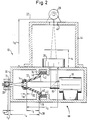
- the structural elements of the imaging apparatus 10 are shown in greater detail in the partial sectional view of Fig. 2.
- the laser diode is mounted in a mount 28 that is fixed with respect to an imager frame 30.
- the collimating lens 14 is positioned within the imager frame by means of a conically shaped collimator housing 32.
- the imager frame 30 has an inwardly extending annular portion 34 having a surface 36 that defines a fixed reference plane 38.
- the conically shaped collimator housing 32 has an annular base 40 that is held against the reference plane 38 defined by surface 36 by spring loading provided by springs 42.
- the scan lens 20 is mounted at one end of an engine frame 44 having an aperture 46 through which the output beam from scan lens 20 is focused at image plane locator 22 that is mounted at the opposite end of the engine frame.
- Fig. 2 The distances between l 2 through l 16 shown in Fig. 2 indicate optical and mechanical distances that are defined in Fig. 4 of the drawings and will be discussed below. The same distances are employed in Fig. 3 which shows a variation of the optical system that does not utilize the beam folding and scanning of mirror 16.
- the scan lens 20 is mounted within a lens housing 48 having a lens flange 50, the surface 52 of which defines one end of distance l 12 (see Figs. 2 and 4).
- the principal planes of the collimating and scan lenses 14 and 20, respectively, are indicated by reference numerals 54 and 56, respectively.
- the spacing between the laser diode 12 and the collimating lens 14 is thermally adjusted to maintain focus on the last system surface i.e., image plane of locator 22 at the photosensitive media 24.
- the proper linear thermal expansions of the imager frame 30 and the collimating lens housing 32 are determined to achieve the correct spacing.
- the spacing requirement takes into account the thermal expansion of the glass(es) employed in the collimating lens 14, the changes in refractive index of the individual glass type(s) and the effect on their optical performance due to the change in wavelength of the laser diode 12 as a function of temperature.
- the required spacing is that which will shift the focus of the nominally collimated laser beam by a precise amount. The precise amount is predicated on the changes in the rest of the optical system due to the same temperature dependent factors mentioned above.
- the focusing power of the scan lens 20 is affected by the thermal expansions of its elements and their change in index of refraction with temperature and the change of wavelength.
- the engine frame 44 separating the scan lens 20 from the photosensitive media 24 increases or decreases in length with temperature based on its coefficient of thermal expansion. Due to the system level temperature dependencies, if the laser beam source module (the laser diode, collimating lens and the mechanical structure holding and separating these components) were thermally compensated to maintain a collimated beam then the final image of scan lens 20 would not remain on the photosensitive media 24.
- S so is equal to negative infinity (the sign change is to maintain sign convention for Eq. 1) with the result that S' so equals to EFL of the scan lens.
- This location establishes the initial location of the image plane 22 for the photosensitive media 24, which is structurally positioned by the engine frame 44.
- thermal compensation is designed into the laser beam source module 58 (the laser diode, collimating lens and the mechanical structure holding and separating these elements).
- the effects of temperature on the complete opto-mechanical system are numerous.
- the mechanical components establishing the separation of the laser diode 12 and collimating lens 14 (S co ) are all affected differently based on their individual coefficients of thermal expansion.
- the engine frame 44 separating the scan lens 20 from the media plane 22 (S' so ).
- Another consideration is the temperature effects on the lenses themselves.
- the parameters of the lenses; EFL, principal plane locations and front and back focal length, are all affected by temperature. These effects are driven by dimensional changes due to coefficients of thermal expansion of the glass elements as well as the metal spacers (if applicable). Additionally, changes to the indices of refraction of the elements due to temperature and in this case due to changes in the wavelength of light emitted by the laser diode 12 as a function of temperature also must be considered.
- the design is approached by starting with the need to maintain the final image of the scan lens 20 on the photosensitive media 24 at some ⁇ T, relative to the initial temperature.
- the value of S ' / s is determined based on the expansion of the engine frame 44, which establishes the distance between the scan lens 20 and the media 24 and image plane 22.
- S ' s l 10 + ( ⁇ 10 ⁇ ⁇ T ⁇ l 10 ) - l 14
- the new EFL of the scan lens must be determined at ⁇ T. This is done by modifying the values of each parameter of the prescription as described above.
- the new EFL, principal plane locations and front and back focal lengths can then be determined by using methods described in References 1 and 2 or by using any number of commercially available lens design computer programs (such as OSLO series II, CODE V, etc.) .
- the desired value of S s can be solved for by reorganizing Eq. 1, given the desired value of S ' / s and the modified EFL of the scan lens 20.
- S s S ' s ⁇ f 2 f 2 - S ' s
- Ss will be slightly different than the initial value of negative infinity since S ' / s and the new EFL of the scan lens are no longer equal.
- This value of S s minus the distance separating the two lenses, l 12 becomes the newly desired S ' / c .
- S ' c - [ S s - [ l 12 + ( ⁇ 12 ⁇ T ⁇ l 12 )]] (sign change is to maintain sign convention).
- This value, S ' / c represents the required imaging performance of the laser beam source module at ⁇ T.
- the present invention provides the required imaging performance using the thermal dependencies of the optics and mechanics within the laser beam source module given the same ⁇ T.
- the collimating lens prescription is modified using the same method as was used for the scan lens.
- the desired distance between the laser diode 12 and the collimating lens 14 (S c ) can be solved for using Equation 5.
- S c S ' c ⁇ f 1 f 1 - S ' c
- the value of S c must thermally adjust to always equal the desired value of S c at T.
- Equations 6 and 7 can be used to determine the final design parameters. First, assign values to all but two of the variables, lengths li and coefficients of thermal expansion ⁇ i (two equations and two unknowns) . By tailoring the choices to the asigning of the lengths and materials to the all but two values, the final solution can be made more practical. It should be noted that this should be the case if the two longest components ( l 2 and l 4 for example) have different coefficients of thermal expansion. Other than that, the material can be selected based on cost, structural parameters etc.
- the result is a complete optical system thermally compensated by a device which is a component of the system.
- the device accomplishing all of the thermal compensation is the laser beam source module 58.
- the chosen materials can be inexpensive castable metals or moldable plastics with a sufficiently stable geometry.
- wall thicknesses are kept uniform so that changes in temperature produce controlled linear growth of the parts.
- aluminum and the polycarbonate LEXAN are described, it should be understood that the invention is not limited to these two materials. Any two materials with different coefficients of thermal expansion can be employed. The thermal expansions of the two materials are used to determine the individual lengths required to provide the required spacing change, with respect to temperature, between the laser diode 12 and the collimating lens 14, thereby providing the precise amount of thermal compensation for the entire system.
Landscapes
- Physics & Mathematics (AREA)
- General Physics & Mathematics (AREA)
- Optics & Photonics (AREA)
- Lens Barrels (AREA)
Claims (9)
- Athermalisierte Abbildungsvorrichtung, mit:dadurch gekennzeichnet,(a) einer Lichtquelle (12) zum Aussenden eines Lichtstrahls;(b) einer Kollimationslinsenvorrichtung (14) zum Kollimieren des Lichtstrahls von der Lichtquelle (12), um einen kollimierten Lichtstrahl zu erzeugen;(c) Vorrichtungen (28, 30; 32, 40, 42) zum Befestigen der Lichtquelle (12) und der Kollimationslinsenvorrichtung (14),
daß sie des weiteren folgendes umfaßt:daß die Vorrichtungen (28, 30; 32, 40, 42) zum Befestigen der Lichtquelle (12) und der Kollimationslinsenvorrichtung (14) Wärmeausdehnungskoeffizienten besitzen, die so festgelegt sind, daß der Abstand zwischen der Lichtquelle (12) und der Kollimationslinsenvorrichtung (14) so reguliert wird, daß die Summenwirkungen aufgrund von Temperaturänderungen auf die Lichtquelle (12), die Kollimationslinsenvorrichtung (14) und die Fokussierlinsenvorrichtung (20) kompensiert werden, um den Brennpunkt auf der Abbildungsebene (22) zu halten.(d) eine Fokussierlinsenvorrichtung (20) zum Fokussieren des kollimierten Lichtstrahls von der Kollimationslinsenvorrichtung (14);(e) eine Abbildungsebene (22), auf der der Lichtstrahl fokussiert wird; und - Athermalisierte Abbildungsvorrichtung nach Anspruch 1, wobei die Vorrichtungen (28, 30; 32, 40, 42) zum Befestigen der Lichtquelle (12) und der Kollimationslinsenvorrichtung (14) eine Vorrichtung (28, 30) zum Befestigen der Lichtquelle (12) und eine Vorrichtung (32, 40, 42) zum Befestigen der Kollimationslinsenvorrichtung (14) umfassen, wobei die Befestigungsvorrichtungen (28, 30; 32, 40, 42) für die Lichtquelle und die Kollimationslinsenvorrichtung unterschiedliche Wärmeausdehnungskoeffizienten besitzen.
- Athermalisierte Abbildungsvorrichtung nach Anspruch 2, wobei die Befestigungsvorrichtung (28, 30) für die Lichtquelle aus Aluminium besteht und die Befestigungsvorrichtung (32, 40, 42) für die Kollimationslinsenvorrichtung aus einem Polycarbonat besteht.
- Athermalisierte Abbildungsvorrichtung nach Anspruch 2, wobei die Befestigungsvorrichtung (32, 40, 42) für die Kollimationslinsenvorrichtung eine im allgemeinen kegelstumpfartige Gestalt aufweist.
- Athermalisierte Abbildungsvorrichtung nach Anspruch 4, wobei die Kollimationslinsenvorrichtung (14) an der Spitze der im allgemeinen kegelstumpfartig gestalteten Halterung (32) befestigt ist.
- Athermalisierte Abbildungsvorrichtung, mit:dadurch gekennzeichnet,(a) einer Lichtquelle (12);(b) einer Vorrichtung (28, 30) zum Befestigen der Lichtquelle (12);(c) einer Kollimationslinsenvorrichtung (14) zum Kollimieren des Lichts von der Lichtquelle (12), um einen kollimierten Lichtstrahl zu erzeugen;(d) einer Vorrichtung (32, 40, 42) zum Befestigen der Kollimationslinsenvorrichtung (14);
daß sie des weiteren folgendes umfaßt:(e) eine Fokussierlinsenvorrichtung (20) zum Fokussieren des kollimierten Lichtstrahls von der Kollimationslinsenvorrichtung (14);(f) Vorrichtungen (30, 44; 48, 50, 52) zum Befestigen der Fokussierlinsenvorrichtung (20);(g) eine Abbildungsebenenlokalisiervorrichtung (22), auf der der Lichtstrahl fokussiert wird;(h) eine Vorrichtung (26, 44) zum Befestigen der Abbildungsebenenlokalisiervorrichtung (22); und(i) daß die Wärmeausdehnungskoeffizienten der Vorrichtungen (28, 30; 32, 40, 42) zum Befestigen der Lichtquellenvorrichtung (12) und der Kollimationslinsenvorrichtung (14) so festgelegt sind, daß der Abstand zwischen der Lichtquellenvorrichtung (12) und der Kollimationslinsenvorrichtung (14) so reguliert wird, daß die Summenwirkungen aufgrund von Temperaturänderungen auf die Lichtquelle (12) und ihre Befestigungsvorrichtung (28, 30), die Kollimationslinsenvorrichtung (14) und ihre Befestigungsvorrichtung (32, 40, 42), die Fokussierlinsenvorrichtung (20) und ihre Befestigungsvorrichtung (30, 44; 48, 50, 52) und die Abbildungsebenenlokalisiervorrichtung (22) und ihre Befestigungsvorrichtung (26, 44) kompensiert werden, um den Brennpunkt auf der Abbildungsebene (22) zu halten. - Verfahren zur thermischen Kompensation einer Abbildungsvorrichtung mit einer Lichtquelle (12), einer Kollimationslinse (14) und einer Fokussierlinse (20), wobei das Verfahren folgende Schritte umfaßt:(1) Ermitteln der Summenwirkungen aufgrund von Temperaturänderungen auf die Lichtquelle (12), die Kollimationslinse (14) und die Fokussierlinse (20); und(2) Verändern des Abstands zwischen der Lichtquelle (12) und der Kollimationslinse (14) als Funktion der Summenwirkungen aufgrund von Temperaturänderungen auf die Lichtquelle (12), die Kollimationslinse (14) und die Fokussierlinse (20), um den Brennpunkt auf einer Abbildungsebene (22) zu halten.
- Verfahren nach Anspruch 7,
dadurch gekennzeichnet,daß die Vorrichtung außerdem eine Lichtquellenhalterung (28, 30), eine Kollimationslinsenhalterung (32, 40, 42), eine Fokussierlinsenhalterung (30, 44; 48, 50, 52) und eine Abbildungsebenenlokalisiervorrichtung (22) umfaßt; undin Schritt (1) des weiteren die Summenwirkungen aufgrund von Temperaturänderungen auf die Lichtquellenhalterung (28, 30), die Kollimationslinsenhalterung (32, 40, 42) und die Fokussierlinsenhalterung (30, 44; 48, 50, 52) berücksichtigt werden; undin Schritt (2) der Abstand zwischen der Lichtquelle (12) und der Kollimationslinse (14) als Funktion der Summenwirkungen aufgrund von Temperaturänderungen auf die Lichtquelle (12), die Kollimationslinse (14), die Fokussierlinse (20) und die Halterungen (28, 30, 32, 40, 42, 44, 48, 50, 52) dafür verändert wird, wobei die Abbildungsebene (22) durch die Abbildungsebenenlokalisiervorrichtung (22) dargestellt wird. - Verfahren nach Anspruch 8, wobei die Lichtquellenhalterung (28, 30) und die Kollimationslinsenhalterung (32, 40, 42) vorgewählte unterschiedliche Wärmeausdehnungskoeffizienten besitzen und wobei der Abstand durch die differentielle Ausdehnung der Lichtquellenhalterung (28, 30) und der Kollimationslinsenhalterung (32, 40, 42) verändert wird.
Applications Claiming Priority (2)
| Application Number | Priority Date | Filing Date | Title |
|---|---|---|---|
| US927607 | 1992-08-10 | ||
| US07/927,607 US5283695A (en) | 1992-08-10 | 1992-08-10 | Athermalized optical system and method |
Publications (2)
| Publication Number | Publication Date |
|---|---|
| EP0585669A1 EP0585669A1 (de) | 1994-03-09 |
| EP0585669B1 true EP0585669B1 (de) | 1998-11-04 |
Family
ID=25454978
Family Applications (1)
| Application Number | Title | Priority Date | Filing Date |
|---|---|---|---|
| EP93112830A Expired - Lifetime EP0585669B1 (de) | 1992-08-10 | 1993-08-10 | Athermalisiertes optisches System und Verfahren |
Country Status (3)
| Country | Link |
|---|---|
| US (1) | US5283695A (de) |
| EP (1) | EP0585669B1 (de) |
| DE (1) | DE69321908T2 (de) |
Families Citing this family (21)
| Publication number | Priority date | Publication date | Assignee | Title |
|---|---|---|---|---|
| US5991102A (en) * | 1994-11-25 | 1999-11-23 | Asahi Kogaku Kogyo Kabushiki Kaisha | Beam protecting device |
| US5570238A (en) * | 1995-03-31 | 1996-10-29 | Lockheed Missiles & Space Company, Inc. | Thermally compensating lens mount |
| US5557474A (en) * | 1995-05-26 | 1996-09-17 | Martin Marietta Corporation | Passive thermal compensation method and apparatus |
| JPH0980330A (ja) * | 1995-09-07 | 1997-03-28 | Minolta Co Ltd | マルチビーム走査光学系 |
| US5881088A (en) * | 1997-01-08 | 1999-03-09 | Trw Inc. | Face-cooled high-power laser optic cell |
| US6040950A (en) * | 1998-01-05 | 2000-03-21 | Intel Corporation | Athermalized mounts for lenses |
| US6134039A (en) * | 1998-01-27 | 2000-10-17 | Psc Scanning, Inc. | Wavelength dependent thermally compensated optical system |
| US6381387B1 (en) | 2000-08-02 | 2002-04-30 | Networks Photonics, Inc. | Athermalization of a wavelength routing element |
| US6814288B2 (en) * | 2000-11-17 | 2004-11-09 | Symbol Technologies, Inc. | Beam shaping system and diverging laser beam for scanning optical code |
| US6631040B1 (en) * | 2002-05-08 | 2003-10-07 | Raytheon Company | Method and apparatus for effecting temperature compensation in an optical apparatus |
| DE10316590A1 (de) * | 2003-04-11 | 2004-10-28 | Carl Zeiss Smt Ag | Lagervorrichtung für ein optisches Element mit einer Fassung |
| JP2005165088A (ja) * | 2003-12-04 | 2005-06-23 | Nec Compound Semiconductor Devices Ltd | 光半導体装置 |
| FR2882110B1 (fr) * | 2005-02-14 | 2010-05-21 | Sagem | Dispositif d'actionnement a rondelles bilames |
| US7680161B2 (en) * | 2005-09-09 | 2010-03-16 | Optoelectronics Co., Ltd. | Temperature compensated laser focusing optics |
| DE102014104974B4 (de) | 2014-04-08 | 2018-03-01 | Jena-Optronik Gmbh | Optische Vorrichtung mit einer Kompensation eines thermooptischen Effekts einer optischen Komponente |
| US10073028B2 (en) * | 2015-09-01 | 2018-09-11 | Spectrasensors, Inc. | Spectrometer optical head assembly |
| US10409015B1 (en) * | 2015-12-15 | 2019-09-10 | Optomind Inc. | Optical receiving device including focusing lens and reflector mounted to housing body and collimating lens mounted to housing cover |
| RU2636257C2 (ru) * | 2016-01-25 | 2017-11-21 | Публичное акционерное общество "Ростовский оптико-механический завод" | Инфракрасный объектив с температурной компенсацией фокусировки |
| CN109596489A (zh) * | 2018-11-29 | 2019-04-09 | 海拉(厦门)电气有限公司 | 一种自动调焦的激光pm2.5粉尘传感器 |
| DE102019107146B4 (de) | 2019-01-30 | 2021-02-25 | Jenoptik Optical Systems Gmbh | Athermale Laseroptik aus Kunststoff |
| CN111290120B (zh) * | 2019-12-26 | 2022-08-02 | 哈尔滨新光光电科技股份有限公司 | 一种调焦光学系统热温稳定性设计方法及调焦光学系统 |
Family Cites Families (7)
| Publication number | Priority date | Publication date | Assignee | Title |
|---|---|---|---|---|
| US4236790A (en) * | 1978-05-15 | 1980-12-02 | Smith Ronald D | Temperature compensated positioning device |
| JPS5915204A (ja) * | 1982-07-17 | 1984-01-26 | Canon Inc | レ−ザユニツト |
| JPS5915205A (ja) * | 1982-07-17 | 1984-01-26 | Canon Inc | レ−ザユニツト |
| JPS61162014A (ja) * | 1985-01-10 | 1986-07-22 | Ricoh Co Ltd | 平行レ−ザ−ビ−ム用光源装置 |
| JPH0685233B2 (ja) * | 1986-06-27 | 1994-10-26 | 株式会社リコー | 半導体レ−ザ−光源装置 |
| NL8700440A (nl) * | 1987-02-23 | 1988-09-16 | Philips Nv | Optische inrichting bevattende een houder met daarin aangebracht een optisch stelsel. |
| US5155616A (en) * | 1989-07-20 | 1992-10-13 | Ricoh Company, Ltd. | Scanning optical system |
-
1992
- 1992-08-10 US US07/927,607 patent/US5283695A/en not_active Expired - Fee Related
-
1993
- 1993-08-10 EP EP93112830A patent/EP0585669B1/de not_active Expired - Lifetime
- 1993-08-10 DE DE69321908T patent/DE69321908T2/de not_active Expired - Fee Related
Also Published As
| Publication number | Publication date |
|---|---|
| US5283695A (en) | 1994-02-01 |
| DE69321908D1 (de) | 1998-12-10 |
| DE69321908T2 (de) | 1999-07-01 |
| EP0585669A1 (de) | 1994-03-09 |
Similar Documents
| Publication | Publication Date | Title |
|---|---|---|
| US5283695A (en) | Athermalized optical system and method | |
| US4815059A (en) | Temperature-compensated optical pick-up device | |
| GB2298289A (en) | Temperature compensated optical scanner | |
| JPH10186230A (ja) | レンズ系及び光学機器 | |
| US6134039A (en) | Wavelength dependent thermally compensated optical system | |
| JPH06215397A (ja) | 積層ファイバ補償リングを備えた受動温度補償光学アセンブリ | |
| US20040066544A1 (en) | Image reading apparatus | |
| JPH06130267A (ja) | 温度補正型光学装置 | |
| EP0420124A2 (de) | Optische Einheit verwendbar für Laserdrucker oder ähnliche Apparate | |
| US20040125192A1 (en) | Light source and light beam scanning unit | |
| EP0415236B1 (de) | Optische Einheit für die Verwendung in einem Laserstrahldrucker oder dergleichen | |
| US7245411B2 (en) | Collimating lens with temperature compensation and an optical scanning apparatus using the same | |
| US5159193A (en) | Optical unit for use in laser beam printer or the like with temperature expansion compensation | |
| KR850004150A (ko) | 광(光)헤드 | |
| EP0431603B1 (de) | Optische Einheit für einen Laserdrucker | |
| EP0441350B1 (de) | Optisches System zur Abtastung mit Lichtstrahlen | |
| CN1300055A (zh) | 光学拾波装置及其制造方法 | |
| KR102294526B1 (ko) | 이중대역 장거리 빗각촬영 비열화 광학계, 이를 이용한 촬영 시스템, 및 이의 방법 | |
| EP0415234A2 (de) | Optische Einheit für Laserstrahldrucker oder dergleichen | |
| EP0637770A2 (de) | Kompaktem Rasterabtastvorrichtung für Abbildungsystem | |
| US5959759A (en) | Multiple beam scanning optical system | |
| JPH0758909A (ja) | イメージ読取装置の結像装置 | |
| US20050152013A1 (en) | Scanning optical system | |
| JP3529086B2 (ja) | 光走査装置 | |
| JP3630732B2 (ja) | 光走査装置 |
Legal Events
| Date | Code | Title | Description |
|---|---|---|---|
| PUAI | Public reference made under article 153(3) epc to a published international application that has entered the european phase |
Free format text: ORIGINAL CODE: 0009012 |
|
| AK | Designated contracting states |
Kind code of ref document: A1 Designated state(s): BE DE FR GB |
|
| 17P | Request for examination filed |
Effective date: 19940908 |
|
| RAP1 | Party data changed (applicant data changed or rights of an application transferred) |
Owner name: MILES INC. |
|
| 17Q | First examination report despatched |
Effective date: 19950120 |
|
| RAP1 | Party data changed (applicant data changed or rights of an application transferred) |
Owner name: BAYER CORPORATION |
|
| GRAG | Despatch of communication of intention to grant |
Free format text: ORIGINAL CODE: EPIDOS AGRA |
|
| GRAG | Despatch of communication of intention to grant |
Free format text: ORIGINAL CODE: EPIDOS AGRA |
|
| GRAH | Despatch of communication of intention to grant a patent |
Free format text: ORIGINAL CODE: EPIDOS IGRA |
|
| GRAH | Despatch of communication of intention to grant a patent |
Free format text: ORIGINAL CODE: EPIDOS IGRA |
|
| GRAH | Despatch of communication of intention to grant a patent |
Free format text: ORIGINAL CODE: EPIDOS IGRA |
|
| GRAH | Despatch of communication of intention to grant a patent |
Free format text: ORIGINAL CODE: EPIDOS IGRA |
|
| GRAA | (expected) grant |
Free format text: ORIGINAL CODE: 0009210 |
|
| AK | Designated contracting states |
Kind code of ref document: B1 Designated state(s): BE DE FR GB |
|
| REF | Corresponds to: |
Ref document number: 69321908 Country of ref document: DE Date of ref document: 19981210 |
|
| ET | Fr: translation filed | ||
| PLBE | No opposition filed within time limit |
Free format text: ORIGINAL CODE: 0009261 |
|
| PGFP | Annual fee paid to national office [announced via postgrant information from national office to epo] |
Ref country code: BE Payment date: 19990921 Year of fee payment: 7 |
|
| 26N | No opposition filed | ||
| PG25 | Lapsed in a contracting state [announced via postgrant information from national office to epo] |
Ref country code: BE Free format text: LAPSE BECAUSE OF NON-PAYMENT OF DUE FEES Effective date: 20000831 |
|
| BERE | Be: lapsed |
Owner name: BAYER CORP. Effective date: 20000831 |
|
| REG | Reference to a national code |
Ref country code: GB Ref legal event code: IF02 |
|
| PGFP | Annual fee paid to national office [announced via postgrant information from national office to epo] |
Ref country code: GB Payment date: 20030805 Year of fee payment: 11 |
|
| PGFP | Annual fee paid to national office [announced via postgrant information from national office to epo] |
Ref country code: FR Payment date: 20030819 Year of fee payment: 11 |
|
| PGFP | Annual fee paid to national office [announced via postgrant information from national office to epo] |
Ref country code: DE Payment date: 20031031 Year of fee payment: 11 |
|
| PG25 | Lapsed in a contracting state [announced via postgrant information from national office to epo] |
Ref country code: GB Free format text: LAPSE BECAUSE OF NON-PAYMENT OF DUE FEES Effective date: 20040810 |
|
| PG25 | Lapsed in a contracting state [announced via postgrant information from national office to epo] |
Ref country code: DE Free format text: LAPSE BECAUSE OF NON-PAYMENT OF DUE FEES Effective date: 20050301 |
|
| GBPC | Gb: european patent ceased through non-payment of renewal fee |
Effective date: 20040810 |
|
| PG25 | Lapsed in a contracting state [announced via postgrant information from national office to epo] |
Ref country code: FR Free format text: LAPSE BECAUSE OF NON-PAYMENT OF DUE FEES Effective date: 20050429 |
|
| REG | Reference to a national code |
Ref country code: FR Ref legal event code: ST |