EP0585875A2 - Kraftwagenvibrationsdampfungsanordnung - Google Patents
Kraftwagenvibrationsdampfungsanordnung Download PDFInfo
- Publication number
- EP0585875A2 EP0585875A2 EP93113903A EP93113903A EP0585875A2 EP 0585875 A2 EP0585875 A2 EP 0585875A2 EP 93113903 A EP93113903 A EP 93113903A EP 93113903 A EP93113903 A EP 93113903A EP 0585875 A2 EP0585875 A2 EP 0585875A2
- Authority
- EP
- European Patent Office
- Prior art keywords
- vibration
- vibrator
- vehicle
- ratio
- vehicle body
- Prior art date
- Legal status (The legal status is an assumption and is not a legal conclusion. Google has not performed a legal analysis and makes no representation as to the accuracy of the status listed.)
- Granted
Links
Images








Classifications
-
- G—PHYSICS
- G10—MUSICAL INSTRUMENTS; ACOUSTICS
- G10K—SOUND-PRODUCING DEVICES; METHODS OR DEVICES FOR PROTECTING AGAINST, OR FOR DAMPING, NOISE OR OTHER ACOUSTIC WAVES IN GENERAL; ACOUSTICS NOT OTHERWISE PROVIDED FOR
- G10K11/00—Methods or devices for transmitting, conducting or directing sound in general; Methods or devices for protecting against, or for damping, noise or other acoustic waves in general
- G10K11/16—Methods or devices for protecting against, or for damping, noise or other acoustic waves in general
- G10K11/175—Methods or devices for protecting against, or for damping, noise or other acoustic waves in general using interference effects; Masking sound
- G10K11/178—Methods or devices for protecting against, or for damping, noise or other acoustic waves in general using interference effects; Masking sound by electro-acoustically regenerating the original acoustic waves in anti-phase
- G10K11/1783—Methods or devices for protecting against, or for damping, noise or other acoustic waves in general using interference effects; Masking sound by electro-acoustically regenerating the original acoustic waves in anti-phase handling or detecting of non-standard events or conditions, e.g. changing operating modes under specific operating conditions
- G10K11/17833—Methods or devices for protecting against, or for damping, noise or other acoustic waves in general using interference effects; Masking sound by electro-acoustically regenerating the original acoustic waves in anti-phase handling or detecting of non-standard events or conditions, e.g. changing operating modes under specific operating conditions by using a self-diagnostic function or a malfunction prevention function, e.g. detecting abnormal output levels
-
- F—MECHANICAL ENGINEERING; LIGHTING; HEATING; WEAPONS; BLASTING
- F16—ENGINEERING ELEMENTS AND UNITS; GENERAL MEASURES FOR PRODUCING AND MAINTAINING EFFECTIVE FUNCTIONING OF MACHINES OR INSTALLATIONS; THERMAL INSULATION IN GENERAL
- F16F—SPRINGS; SHOCK-ABSORBERS; MEANS FOR DAMPING VIBRATION
- F16F15/00—Suppression of vibrations in systems; Means or arrangements for avoiding or reducing out-of-balance forces, e.g. due to motion
- F16F15/02—Suppression of vibrations of non-rotating, e.g. reciprocating systems; Suppression of vibrations of rotating systems by use of members not moving with the rotating systems
-
- B—PERFORMING OPERATIONS; TRANSPORTING
- B60—VEHICLES IN GENERAL
- B60K—ARRANGEMENT OR MOUNTING OF PROPULSION UNITS OR OF TRANSMISSIONS IN VEHICLES; ARRANGEMENT OR MOUNTING OF PLURAL DIVERSE PRIME-MOVERS IN VEHICLES; AUXILIARY DRIVES FOR VEHICLES; INSTRUMENTATION OR DASHBOARDS FOR VEHICLES; ARRANGEMENTS IN CONNECTION WITH COOLING, AIR INTAKE, GAS EXHAUST OR FUEL SUPPLY OF PROPULSION UNITS IN VEHICLES
- B60K5/00—Arrangement or mounting of internal-combustion or jet-propulsion units
- B60K5/12—Arrangement of engine supports
-
- G—PHYSICS
- G01—MEASURING; TESTING
- G01K—MEASURING TEMPERATURE; MEASURING QUANTITY OF HEAT; THERMALLY-SENSITIVE ELEMENTS NOT OTHERWISE PROVIDED FOR
- G01K11/00—Measuring temperature based upon physical or chemical changes not covered by groups G01K3/00, G01K5/00, G01K7/00 or G01K9/00
- G01K11/12—Measuring temperature based upon physical or chemical changes not covered by groups G01K3/00, G01K5/00, G01K7/00 or G01K9/00 using changes in colour, translucency or reflectance
- G01K11/16—Measuring temperature based upon physical or chemical changes not covered by groups G01K3/00, G01K5/00, G01K7/00 or G01K9/00 using changes in colour, translucency or reflectance of organic materials
-
- G—PHYSICS
- G10—MUSICAL INSTRUMENTS; ACOUSTICS
- G10K—SOUND-PRODUCING DEVICES; METHODS OR DEVICES FOR PROTECTING AGAINST, OR FOR DAMPING, NOISE OR OTHER ACOUSTIC WAVES IN GENERAL; ACOUSTICS NOT OTHERWISE PROVIDED FOR
- G10K11/00—Methods or devices for transmitting, conducting or directing sound in general; Methods or devices for protecting against, or for damping, noise or other acoustic waves in general
- G10K11/16—Methods or devices for protecting against, or for damping, noise or other acoustic waves in general
- G10K11/175—Methods or devices for protecting against, or for damping, noise or other acoustic waves in general using interference effects; Masking sound
- G10K11/178—Methods or devices for protecting against, or for damping, noise or other acoustic waves in general using interference effects; Masking sound by electro-acoustically regenerating the original acoustic waves in anti-phase
- G10K11/1781—Methods or devices for protecting against, or for damping, noise or other acoustic waves in general using interference effects; Masking sound by electro-acoustically regenerating the original acoustic waves in anti-phase characterised by the analysis of input or output signals, e.g. frequency range, modes, transfer functions
- G10K11/17821—Methods or devices for protecting against, or for damping, noise or other acoustic waves in general using interference effects; Masking sound by electro-acoustically regenerating the original acoustic waves in anti-phase characterised by the analysis of input or output signals, e.g. frequency range, modes, transfer functions characterised by the analysis of the input signals only
- G10K11/17823—Reference signals, e.g. ambient acoustic environment
-
- G—PHYSICS
- G10—MUSICAL INSTRUMENTS; ACOUSTICS
- G10K—SOUND-PRODUCING DEVICES; METHODS OR DEVICES FOR PROTECTING AGAINST, OR FOR DAMPING, NOISE OR OTHER ACOUSTIC WAVES IN GENERAL; ACOUSTICS NOT OTHERWISE PROVIDED FOR
- G10K11/00—Methods or devices for transmitting, conducting or directing sound in general; Methods or devices for protecting against, or for damping, noise or other acoustic waves in general
- G10K11/16—Methods or devices for protecting against, or for damping, noise or other acoustic waves in general
- G10K11/175—Methods or devices for protecting against, or for damping, noise or other acoustic waves in general using interference effects; Masking sound
- G10K11/178—Methods or devices for protecting against, or for damping, noise or other acoustic waves in general using interference effects; Masking sound by electro-acoustically regenerating the original acoustic waves in anti-phase
- G10K11/1781—Methods or devices for protecting against, or for damping, noise or other acoustic waves in general using interference effects; Masking sound by electro-acoustically regenerating the original acoustic waves in anti-phase characterised by the analysis of input or output signals, e.g. frequency range, modes, transfer functions
- G10K11/17821—Methods or devices for protecting against, or for damping, noise or other acoustic waves in general using interference effects; Masking sound by electro-acoustically regenerating the original acoustic waves in anti-phase characterised by the analysis of input or output signals, e.g. frequency range, modes, transfer functions characterised by the analysis of the input signals only
- G10K11/17825—Error signals
-
- G—PHYSICS
- G10—MUSICAL INSTRUMENTS; ACOUSTICS
- G10K—SOUND-PRODUCING DEVICES; METHODS OR DEVICES FOR PROTECTING AGAINST, OR FOR DAMPING, NOISE OR OTHER ACOUSTIC WAVES IN GENERAL; ACOUSTICS NOT OTHERWISE PROVIDED FOR
- G10K11/00—Methods or devices for transmitting, conducting or directing sound in general; Methods or devices for protecting against, or for damping, noise or other acoustic waves in general
- G10K11/16—Methods or devices for protecting against, or for damping, noise or other acoustic waves in general
- G10K11/175—Methods or devices for protecting against, or for damping, noise or other acoustic waves in general using interference effects; Masking sound
- G10K11/178—Methods or devices for protecting against, or for damping, noise or other acoustic waves in general using interference effects; Masking sound by electro-acoustically regenerating the original acoustic waves in anti-phase
- G10K11/1785—Methods, e.g. algorithms; Devices
- G10K11/17853—Methods, e.g. algorithms; Devices of the filter
- G10K11/17854—Methods, e.g. algorithms; Devices of the filter the filter being an adaptive filter
-
- G—PHYSICS
- G10—MUSICAL INSTRUMENTS; ACOUSTICS
- G10K—SOUND-PRODUCING DEVICES; METHODS OR DEVICES FOR PROTECTING AGAINST, OR FOR DAMPING, NOISE OR OTHER ACOUSTIC WAVES IN GENERAL; ACOUSTICS NOT OTHERWISE PROVIDED FOR
- G10K11/00—Methods or devices for transmitting, conducting or directing sound in general; Methods or devices for protecting against, or for damping, noise or other acoustic waves in general
- G10K11/16—Methods or devices for protecting against, or for damping, noise or other acoustic waves in general
- G10K11/175—Methods or devices for protecting against, or for damping, noise or other acoustic waves in general using interference effects; Masking sound
- G10K11/178—Methods or devices for protecting against, or for damping, noise or other acoustic waves in general using interference effects; Masking sound by electro-acoustically regenerating the original acoustic waves in anti-phase
- G10K11/1785—Methods, e.g. algorithms; Devices
- G10K11/17857—Geometric disposition, e.g. placement of microphones
-
- G—PHYSICS
- G10—MUSICAL INSTRUMENTS; ACOUSTICS
- G10K—SOUND-PRODUCING DEVICES; METHODS OR DEVICES FOR PROTECTING AGAINST, OR FOR DAMPING, NOISE OR OTHER ACOUSTIC WAVES IN GENERAL; ACOUSTICS NOT OTHERWISE PROVIDED FOR
- G10K11/00—Methods or devices for transmitting, conducting or directing sound in general; Methods or devices for protecting against, or for damping, noise or other acoustic waves in general
- G10K11/16—Methods or devices for protecting against, or for damping, noise or other acoustic waves in general
- G10K11/175—Methods or devices for protecting against, or for damping, noise or other acoustic waves in general using interference effects; Masking sound
- G10K11/178—Methods or devices for protecting against, or for damping, noise or other acoustic waves in general using interference effects; Masking sound by electro-acoustically regenerating the original acoustic waves in anti-phase
- G10K11/1787—General system configurations
- G10K11/17879—General system configurations using both a reference signal and an error signal
- G10K11/17883—General system configurations using both a reference signal and an error signal the reference signal being derived from a machine operating condition, e.g. engine RPM or vehicle speed
-
- G—PHYSICS
- G10—MUSICAL INSTRUMENTS; ACOUSTICS
- G10K—SOUND-PRODUCING DEVICES; METHODS OR DEVICES FOR PROTECTING AGAINST, OR FOR DAMPING, NOISE OR OTHER ACOUSTIC WAVES IN GENERAL; ACOUSTICS NOT OTHERWISE PROVIDED FOR
- G10K2210/00—Details of active noise control [ANC] covered by G10K11/178 but not provided for in any of its subgroups
- G10K2210/10—Applications
- G10K2210/105—Appliances, e.g. washing machines or dishwashers
- G10K2210/1053—Hi-fi, i.e. anything involving music, radios or loudspeakers
-
- G—PHYSICS
- G10—MUSICAL INSTRUMENTS; ACOUSTICS
- G10K—SOUND-PRODUCING DEVICES; METHODS OR DEVICES FOR PROTECTING AGAINST, OR FOR DAMPING, NOISE OR OTHER ACOUSTIC WAVES IN GENERAL; ACOUSTICS NOT OTHERWISE PROVIDED FOR
- G10K2210/00—Details of active noise control [ANC] covered by G10K11/178 but not provided for in any of its subgroups
- G10K2210/10—Applications
- G10K2210/106—Boxes, i.e. active box covering a noise source; Enclosures
-
- G—PHYSICS
- G10—MUSICAL INSTRUMENTS; ACOUSTICS
- G10K—SOUND-PRODUCING DEVICES; METHODS OR DEVICES FOR PROTECTING AGAINST, OR FOR DAMPING, NOISE OR OTHER ACOUSTIC WAVES IN GENERAL; ACOUSTICS NOT OTHERWISE PROVIDED FOR
- G10K2210/00—Details of active noise control [ANC] covered by G10K11/178 but not provided for in any of its subgroups
- G10K2210/10—Applications
- G10K2210/128—Vehicles
-
- G—PHYSICS
- G10—MUSICAL INSTRUMENTS; ACOUSTICS
- G10K—SOUND-PRODUCING DEVICES; METHODS OR DEVICES FOR PROTECTING AGAINST, OR FOR DAMPING, NOISE OR OTHER ACOUSTIC WAVES IN GENERAL; ACOUSTICS NOT OTHERWISE PROVIDED FOR
- G10K2210/00—Details of active noise control [ANC] covered by G10K11/178 but not provided for in any of its subgroups
- G10K2210/10—Applications
- G10K2210/128—Vehicles
- G10K2210/1282—Automobiles
-
- G—PHYSICS
- G10—MUSICAL INSTRUMENTS; ACOUSTICS
- G10K—SOUND-PRODUCING DEVICES; METHODS OR DEVICES FOR PROTECTING AGAINST, OR FOR DAMPING, NOISE OR OTHER ACOUSTIC WAVES IN GENERAL; ACOUSTICS NOT OTHERWISE PROVIDED FOR
- G10K2210/00—Details of active noise control [ANC] covered by G10K11/178 but not provided for in any of its subgroups
- G10K2210/10—Applications
- G10K2210/129—Vibration, e.g. instead of, or in addition to, acoustic noise
-
- G—PHYSICS
- G10—MUSICAL INSTRUMENTS; ACOUSTICS
- G10K—SOUND-PRODUCING DEVICES; METHODS OR DEVICES FOR PROTECTING AGAINST, OR FOR DAMPING, NOISE OR OTHER ACOUSTIC WAVES IN GENERAL; ACOUSTICS NOT OTHERWISE PROVIDED FOR
- G10K2210/00—Details of active noise control [ANC] covered by G10K11/178 but not provided for in any of its subgroups
- G10K2210/30—Means
- G10K2210/301—Computational
- G10K2210/3039—Nonlinear, e.g. clipping, numerical truncation, thresholding or variable input and output gain
-
- G—PHYSICS
- G10—MUSICAL INSTRUMENTS; ACOUSTICS
- G10K—SOUND-PRODUCING DEVICES; METHODS OR DEVICES FOR PROTECTING AGAINST, OR FOR DAMPING, NOISE OR OTHER ACOUSTIC WAVES IN GENERAL; ACOUSTICS NOT OTHERWISE PROVIDED FOR
- G10K2210/00—Details of active noise control [ANC] covered by G10K11/178 but not provided for in any of its subgroups
- G10K2210/30—Means
- G10K2210/301—Computational
- G10K2210/3046—Multiple acoustic inputs, multiple acoustic outputs
-
- G—PHYSICS
- G10—MUSICAL INSTRUMENTS; ACOUSTICS
- G10K—SOUND-PRODUCING DEVICES; METHODS OR DEVICES FOR PROTECTING AGAINST, OR FOR DAMPING, NOISE OR OTHER ACOUSTIC WAVES IN GENERAL; ACOUSTICS NOT OTHERWISE PROVIDED FOR
- G10K2210/00—Details of active noise control [ANC] covered by G10K11/178 but not provided for in any of its subgroups
- G10K2210/30—Means
- G10K2210/321—Physical
- G10K2210/3212—Actuator details, e.g. composition or microstructure
-
- G—PHYSICS
- G10—MUSICAL INSTRUMENTS; ACOUSTICS
- G10K—SOUND-PRODUCING DEVICES; METHODS OR DEVICES FOR PROTECTING AGAINST, OR FOR DAMPING, NOISE OR OTHER ACOUSTIC WAVES IN GENERAL; ACOUSTICS NOT OTHERWISE PROVIDED FOR
- G10K2210/00—Details of active noise control [ANC] covered by G10K11/178 but not provided for in any of its subgroups
- G10K2210/30—Means
- G10K2210/321—Physical
- G10K2210/3221—Headrests, seats or the like, for personal ANC systems
-
- G—PHYSICS
- G10—MUSICAL INSTRUMENTS; ACOUSTICS
- G10K—SOUND-PRODUCING DEVICES; METHODS OR DEVICES FOR PROTECTING AGAINST, OR FOR DAMPING, NOISE OR OTHER ACOUSTIC WAVES IN GENERAL; ACOUSTICS NOT OTHERWISE PROVIDED FOR
- G10K2210/00—Details of active noise control [ANC] covered by G10K11/178 but not provided for in any of its subgroups
- G10K2210/30—Means
- G10K2210/321—Physical
- G10K2210/3225—Radio or other sources used in ANC for transfer function estimation; Means to avoid interference between desired signals, e.g. from a car stereo, and the ANC signal
Definitions
- This invention relates to a vibration damping system for a vehicle for damping vibration of a particular vibrating element such as the vehicle body, air in the cabin or the like mainly generated by vibration of a power unit, and more particularly to a vibration damping system for a vehicle which has a vibrator for vibrating the particular vibrating element and vibrates the particular vibrating element in the phase reverse to that of the vibration of the particular vibrating element and in the amplitude equal to that of the vibration of the same, thereby damping the vibration of the vehicle body or air in the cabin (noise).
- a vibration damping system for a vehicle comprising, in addition to the vibrator, a vibration sensor which detects vibration of a particular vibrating element on the vehicle body and a drive control means which performs calculation on the basis of the detecting signal from the vibration sensor and causes the vibrator to vibrate the particular vibrating element so that the vibration of the particular vibrating element is damped.
- vibration damping systems there are those in which an optimization technique is employed in the calculation performed by the drive control means as in the vibration damping system disclosed in the above identified patent publication and there are those in which the optimization technique is not employed.
- the former systems are generally arranged as shown in Figure 33.
- the vibration damping system shown in Figure 33 is for damping vibration of air in the cabin (noise) generated due to vibration of an engine E (as the power unit) and comprises a plurality of microphones 2 (m in number) which are disposed in predetermined positions in the cabin and detect vibration of air in the respective predetermined positions, a plurality of speakers 4 (i in number) which are disposed in predetermined positions in the cabin and vibrate air in the cabin to damp the vibration of air, and a drive control means 6 which generates drive signals y1 to y i for controlling the speakers 4.
- the vibration damping system is further provided with a reference signal generating means 8 which detects an ignition pulse signal w, generated in relation to the revolution speed of the engine E, from an ignition coil 24 and shapes the waveform of the ignition pulse signal w, thereby generating a reference signal x.
- the microphones 2 detect the vibration due to the vibration of the engine E together with the vibration generated by the speakers 4 and output the result of the detection as detecting signals e1 to e m .
- the detecting signals e1 to e m are input into the drive control means 6 through amplifiers 16 and A/D convertors 18.
- the reference signal x generated by the reference signal generating means 8 is input into the drive control means 6 through an amplifier 12 and an A/D convertor 14.
- the drive control means 6 comprises adaptive filters F1 to Fi which adjust the phase and the amplitude of the reference signal x and an adaptive algorithm section 10 which updates every moment the factors of the adaptive filters F1 to Fi so that the detecting signals e1 to e m input from the microphones 2 are minimized, and outputs the signals passing through the adaptive filters F1 to Fi as the drive signals y1 to y i .
- the adaptive algorithm for updating the factors of the adaptive filters F1 to Fi there have been known Least Mean Square Method, Newton Method, Simplex Method, Powell Method and the like. In this example, Least Mean Square Method is employed.
- the reference signal x is input into the adaptive algorithm section 10 through a digital filter H° IM (I standing for 1, 2, ... , i and M standing for 1, 2, ... , m).
- the digital filter H° IM is modeled on the transmission properties between I-th speaker 4 and M-th microphone 2 and the space distance between the speaker 4 and the microphone 2 is thus interpolated.
- a spectral analysis shows that vibration of a power unit such as an engine includes many sinusoidal vibration components having frequencies of integral multiples of the engine rpm and that the vibration components have different levels and one or more particular components have especially high levels.
- the vibration component having a frequency of twice the engine speed (will be referred to as "the secondary component", hereinbelow) has an especially high level, and control is generally effected with intention of damping the vibration caused by the secondary component.
- the vibration damping system described above is arranged to damp the vibration of air in the cabin (noise) caused by the engine vibration
- solid elements of the vehicle body such as a frame of the vehicle body, panels of the vehicle body, seats, a steering wheel and the like are also caused to vibrate by the engine vibration. Accordingly it is preferred that not only the vibration of air in the cabin but also the vibration of the solid elements be damped.
- the vibration damping system having speakers and microphones respectively as the vibrators and the vibration sensors cannot damp the vibration of the solid elements though can damp the vibration of air.
- the primary object of the present invention is to provide a vibration damping system for a vehicle which can damp satisfactorily and efficiently both the vibration of air and the vibration of the solid elements caused by the vibration of the power unit.
- a vibration damping system for a vehicle comprising a vibration detecting means which detects vibration of solid elements on the vehicle and vibration of air inside the vehicle, a first vibrator which supports a power unit relative to the vehicle body and directly vibrates the vehicle body, a second vibrator which directly vibrates air inside the vehicle body, a drive control means which performs calculation on the basis of a detecting signal from the vibration detecting means and controls the first and the second vibrators on the basis of the result of the calculation so that the vibration of the solid element and the vibration of air inside the vehicle body are damped, and a ratio changing means which changes the vibrator control ratio of the first and second vibrators according to the condition of a predetermined factor of the vehicle.
- solid elements means vehicle body components such as a frame of the vehicle body, panels of the vehicle body, seats, a steering wheel and the like.
- power unit means an engine, a transmission and/or the like.
- the vibration detecting means may be a vibration sensor which can detect both the vibration of the solid element and the vibration of air inside the vehicle body, or may be a combination of a vibration sensor which can detect the vibration of the solid element and vibration sensor which can detect the vibration of air inside the vehicle body.
- the vibrator control ratio is changed by changing the ratio of the part of the operational power of the drive control means allotted to the control of the first vibrator to the part of the operational power of the drive control means allotted to the control of the second vibrator.
- the vibrator control ratio is changed by changing the ratio of the proportion of the amount of the vibration of the first vibrator set by the drive control means to the amount of the vibration of the first vibrator optimal to damp the vibration of the solid element to the proportion of the amount of the vibration of the second vibrator set by the drive control means to the amount of the vibration of the second vibrator optimal to damp the vibration of the air inside the vehicle body.
- the amount of the vibration of the first vibrator optimal to damp the vibration of the solid element or "the amount of the vibration of the second vibrator optimal to damp the vibration of the air inside the vehicle body” means the amount of the vibration by which the vibrator is to be vibrated to optimally damp the vibration of the solid element or air inside the vehicle.
- Said predetermined factor of the vehicle may be the engine speed, the vehicle speed, the loudness of the audio system on the vehicle, the degree of opening of the window, the number of the passengers on the vehicle, the level of noise included in the detecting signal from the vibration detecting means, the electric load, the acceleration and deceleration of the vehicle, the air flow of an air-conditioner on the vehicle, whether the vibrators are in the normal condition or in an abnormal condition, the vibration of the power unit or the like.
- the vibration damping system of the present invention may be further provided with a manual ratio setting means for manually setting the vibrator control ratio.
- a vibration damping system for a vehicle comprising a vibration detecting means which detects vibration of solid elements on the vehicle and vibration of air inside the vehicle, a vibrator group consisting of a first vibrator which supports a power unit relative to the vehicle body and directly vibrates the vehicle body and a second vibrator which directly vibrates air inside the vehicle body, and a drive control means which performs calculation on the basis of a detecting signal from the vibration detecting means and outputs a single drive signal to the vibrator group on the basis of the result of the calculation, the first and the second vibrators forming the vibrator group being driven by the single drive signal for the vibrator group so that the vibration of the solid element and the vibration of air inside the vehicle body are damped.
- a vibration damping system for a vehicle comprising a vibration detecting means which detects vibration of solid elements on the vehicle and vibration of air inside the vehicle, a vibrator group consisting of a first vibrator which supports a power unit relative to the vehicle body and directly vibrates the vehicle body and a second vibrator which directly vibrates air inside the vehicle body, a drive control means which performs calculation on the basis of a detecting signal from the vibration detecting means and outputs a single drive signal to the vibrator group on the basis of the result of the calculation which drive signal drives the first and the second vibrators forming the vibrator group so that the vibration of the solid element and the vibration of air inside the vehicle body are damped, and a drive signal separating means which separates the drive signal by frequency into first and second drive signals for the first and second vibrators forming the vibrator group, the first and second vibrators forming the vibrator group being driven respectively by the first and second drive signals.
- a vibration damping system for a vehicle comprising a vibration sensor group consisting of a first vibration sensor which detects vibration of solid elements on the vehicle and a second vibration sensor which detects vibration of air inside the vehicle, a vibrator group consisting of a first vibrator which supports a power unit relative to the vehicle body and directly vibrates the vehicle body and a second vibrator which directly vibrates air inside the vehicle body, a detecting signal mixing means which mixes detecting signals of the first and second vibration sensors into a detecting signal, and a drive control means which performs calculation on the basis of the detecting signal from the detecting signal mixing means and outputs a single drive signal to the vibrator group on the basis of the result of the calculation which single drive signal drives the first and the second vibrators forming the vibrator group so that the vibration of the solid element and the vibration of air inside the vehicle body are damped, the first and second vibrators forming the vibrator group being driven by the single drive signal.
- a vibration damping system for a vehicle comprising a vibration sensor group consisting of a first vibration sensor which detects vibration of solid elements on the vehicle and a second vibration sensor which detects vibration of air inside the vehicle, a vibrator group consisting of a first vibrator which supports a power unit relative to the vehicle body and directly vibrates the vehicle body and a second vibrator which directly vibrates air inside the vehicle body, a detecting signal mixing means which mixes detecting signals of the first and second vibration sensors into a detecting signal, a drive control means which performs calculation on the basis of the detecting signal from the detecting signal mixing means and outputs a single drive signal to the vibrator group on the basis of the result of the calculation which drive signal drives the first and the second vibrators forming the vibrator group so that the vibration of the solid element and the vibration of air inside the vehicle body are damped, and a drive signal separating means which separates the single drive signal by frequency into first and second drive signals for the first and second vibrators forming the vibrator
- the vibration of the solid element is damped by the first vibrator and the noise in the cabin is damped by the second vibrator. Accordingly, both the vibration of the solid element and the noise in the cabin can be effectively damped.
- the vibrator control ratio is changed according to a predetermined factor of the vehicle, an optimal damping of the vibration of the solid element and the noise in the cabin can be realized.
- the vibrator control ratio is changed by changing the ratio of the part of the operational power of the drive control means allotted to the control of the first vibrator to the part of the operational power of the drive control means allotted to the control of the second vibrator, one of the vibration of the solid element and the noise in the cabin which is to be preferentially damped can be effectively damped without increasing the operational load on the drive control means.
- the vibrator control ratio is changed by changing the ratio of the proportion of the amount of the vibration of the first vibrator set by the drive control means to the amount of the vibration of the first vibrator optimal to damp the vibration of the solid element to the proportion of the amount of the vibration of the second vibrator set by the drive control means to the amount of the vibration of the second vibrator optimal to damp the vibration of the air inside the vehicle body, the vibrator driving of which is not expected to result in satisfactory damping of the vibration is driven by an amount less than the amount optimal to damp the vibration, whereby electric power is saved.
- the operational load on the drive control means can be reduced.
- the drive signal separating means is provided and the single drive signal is separated by frequency into first and second drive signals for the first and second vibrators forming the vibrator group, generation of distortion in the first and second vibrators which can be generated when the drive signal for each vibrator includes a component which does not conform to the vibrator can be prevented.
- the operational load on the drive control means can be reduced.
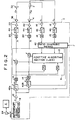
- the vibration damping system of this embodiment comprises an acceleration sensor 32 (as a vibration sensor) which is disposed near the mounting portion of the engine E to the vehicle body 1 and detects the vibration of the vehicle body 1, a microphone 2 which is disposed near a seat in the cabin (preferably disposed near the ears of the passenger seated on the seats) and detects the vibration of air in the cabin, a vibrating engine mount 36 which supports the engine E relative to the vehicle body 1 and directly vibrates the vehicle body 1, a speaker 4 which is disposed in an instrument panel in the cabin and directly vibrates air in the cabin, and a controller C which drives the vibrating engine mount 36 and the speaker 4.
- the acceleration sensor 32, the microphone 2, the vibrating engine mount 36 and the speaker 4 are each one in number, they may be plural in number.
- the controller C comprises a reference signal generating means 8 which generates a reference signal x relating to the vibration of the engine E on the basis of an ignition pulse signal w generated by an ignition coil 24, attenuators 40a and 40b which attenuates the reference signal x input from the reference signal generating means 8 by a predetermined amount, a drive control means 6 which generates drive signals y1 and y2 for driving the vibrating engine mount 36 and the speaker 4 on the basis of the adjusted reference signals x1 and x2 output from the attenuators 40a and 40b, and a ratio changing means 42 which changes the attenuation rate of the reference signal x by the attenuators 40a and 40b and the control ratio of the vibrating engine mount 36 and the speaker 4 by the drive control means 6 according to the condition of a predetermined factor J.
- the drive control means 6 comprises adaptive filters F1 and F2 which adjust the phase and the amplitude of the adjusted reference signals x1 and x2 and an adaptive algorithm section 10 which adjusts the adaptive filters F1 and F2 so that the detecting signals e1 to e2 respectively input from the acceleration sensor 32 and the microphones 2 are minimized.
- Least Mean Square Method is employed as the adaptive algorithm for adjusting the adaptive filters F1 and F2 and for this purpose, the drive control means 6 is provided with digital filters H° LM (L standing for 1, 2 and M standing for 1, 2) which are modeled on the transmission properties between the vibrating engine mount 36 and the acceleration sensor 32 and between the speaker 4 and the microphone 2.
- controller C has therein an amplifier 12 which amplifies the reference signal x, A/D convertors 14 which convert the adjusted reference signals x1 and x2 to digital signals, D/A convertors 20 which convert the drive signals y1 and y2 to analog signals, low-pass filters 44, amplifiers 22, amplifiers 16 which amplify the detecting signals e1 and e2, low-pass filters 46, and A/D convertors 18 which convert the detecting signals e1 and e2 passing through the low-pass filters 46 to digital signals.
- amplifier 12 which amplifies the reference signal x
- A/D convertors 14 which convert the adjusted reference signals x1 and x2 to digital signals
- D/A convertors 20 which convert the drive signals y1 and y2 to analog signals
- low-pass filters 44 amplifiers 22
- amplifiers 16 which amplify the detecting signals e1 and e2, low-pass filters 46
- A/D convertors 18 which convert the detecting signals e1 and e2 passing through
- the ratio changing means 42 changes the vibrator control ratio by changing the input frequencies at which the detecting signals e1 and e2 from the acceleration sensor 32 and the microphone 2 are input into the drive control means 6 according to the condition of a predetermined factor J thereby changing the ratio of the part of the operational power of the drive control means 6 allotted to the control of the vibrating engine mount 36 to that allotted to the control of the speaker 4. Change of the vibrator control ratio by the ratio changing means 42 for various factors will be described, hereinbelow.
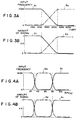
- Figures 3A and 3B respecively show the relation of the input frequencies of the detecting signals e1 and e2 to the engine speed and the relation of the amount of the adjusted reference signals x1 and x2 input into the drive control means to the engine speed.
- the level of vibration of the solid elements caused by vibration of the power unit is higher than that of air in the cabin when the engine speed is low and lower than the same when the engine speed is high.
- the ratio changing means 42 increases the input frequency of the detecting signal e1 from the acceleration sensor 32 at which the detecting signal e1 is input into the drive control means 6 in a predetermined time interval and nullifies the input frequency of the detecting signal e2 from the microphone 2. Since the drive control means 6 performs calculation for updating the factor of the adaptive filters F1 and F2 according to the input frequencies of the detecting signals e1 and e2, all the operational power of the drive control means 6 is allotted to the control of the vibrating engine mount 36 when the input frequency of the detecting signal e1 from the acceleration sensor 32 is increased and the input frequency of the detecting signal e2 from the microphone 2 is nullified.
- the ratio changing means 42 reduces the input frequency of the detecting signal e1 from the acceleration sensor 32 as the engine speed increases and increases the input frequency of the detecting signal e2 from the microphone 2 as the engine speed increases.
- the operational power of the drive control means 6 is uniformly allotted to the control of the vibrating engine mount 36 and the control of the speaker 4.
- the ratio changing means 42 nullifies the input frequency of the detecting signal e1 from the acceleration sensor 32 and increases the input frequency of the detecting signal e2 from the microphone 2. In this case, all the operational power of the drive control means 6 is allotted to the control of the speaker 4.
- the ratio changing means 42 causes the attenuators 40a and 40b to increase the amount of the adjusted reference signal x1 input into the adaptive filter F1 (the reference signal x output from the amplifier 12 is input into the filter F1 as it is without attenuation) and nullify the adjusted reference signal x2 input into the adaptive filter F2 in the low engine speed range, to gradually reduce the amount of the adjusted reference signal x1 as the engine speed increases and gradually increase the adjusted reference signal x2 as the engine speed increases in the middle engine speed range, and to nullify the adjusted reference signal x1 and increase the amount of the adjusted reference signal x2 in the high engine speed range.
- the vibration damping system of this embodiment having the ratio changing means 42 which changes the input frequencies of the detecting signals e1 and e2 and amounts of the adjusted reference signals x1 and x2 input into the adaptive filters F1 and F2 in the manner described above operates as follows.
- the acceleration sensor 32 shown in Figures 1 and 2 detects the vibration of the vehicle body 1 and outputs the detecting signal e1 and the microphone 2 detects the vibration of air in the cabin (noise in the cabin) and outputs the detecting signal e2.
- the detecting signals e1 and e2 are input into the drive control means 6 through the ratio changing means 42 which changes the input frequencies of the detecting signals e1 and e2 to the drive control means 6 according to the engine speed as described above.
- the input frequency of the detecting signal e1 is increased and the input frequency of the detecting signal e2 is nullified. Since the drive control means 6 updates the factors of the adaptive filters F1 and F2 so that the signal levels are minimized each time the detecting signals e1 and e2 are input, the factor of the adaptive filter F2 is not updated though the factor of the adaptive filter F1 is updated and the signal level of the detecting signal e1 is minimized.
- the ratio changing means 42 increases the amount of the adjusted reference signal x1 input into the adaptive filter F1 and nullifies the amount of the adjusted reference signal x2 input into the adaptive filter F2 in the low engine speed range, no adjusted reference signal x2 is input into the adaptive filter F2 though the adjusted reference signals x1 are successively input into the adaptive filter F1. Accordingly the drive signals y1 are successively generated to drive the vibrating engine mount 36 but no drive signal y2 is generated and the speaker 4 is not driven. In this manner, when the engine speed is in the low engine speed range, damping of the vibration of the vehicle body 1 is preferentially effected and damping of the noise in the cabin is not effected.
- the vibration of the vehicle body 1 can be effectively damped well following the fluctuation thereof. Further since the input frequency of the detecting signal e2 is nullified though the input frequency of the detecting signal e1 is increased, the operational load on the drive control means 6 is not increased. Further since the speaker 4 driving of which will be almost useless in the low engine speed range is not driven, consumption of electric power can be suppressed.
- the input frequency of the detecting signal e2 is increased and the input frequency of the detecting signal e1 is nullified, whereby the noise in the cabin can be effectively damped without increasing the operational load on the drive control means 6 and consumption of electric power can be Suppressed by not driving the vibrating engine mount 36, driving of which will be almost useless in the high engine speed range.
- the vibration of the vehicle body 1 is damped in preference to the noise in the cabin and the degree of the preference is increased toward the low engine speed range
- the noise in the cabin is damped in preference to the vibration of the vehicle body 1 and the degree of the preference is increased toward the high engine speed range.
- the vibration which more bothers the passengers is effectively damped without increasing the operational load on the drive control means 6.
- Figures 4A and 4B respecively show the relation of the input frequencies of the detecting signals e1 and e2 to the vehicle speed and the relation of the amount of the adjusted reference signals x1 and x2 input into the drive control means 6 to the vehicle speed when the ratio changing means 42 changes the vibrator control ratio according to the vehicle speed.
- the level of vibration of the solid elements caused by vibration of the power unit is higher than that of air in the cabin when the vehicle speed is in a low speed range and lower than the same when the vehicle speed is in a high speed range. Further when the vehicle speed is in a highest speed range, the level of vibration of air due to external disturbances rather than to vibration of the power unit such as road noise, wind noise and the like prevails.
- the ratio changing means 42 increases the input frequency of the detecting signal e1 from the acceleration sensor 32 and nullifies the input frequency of the detecting signal e2 from the microphone 2, thereby allotting all the operational power of the drive control means 6 to the control of the vibrating engine mount 36.
- the ratio changing means 42 nullifies the input frequency of the detecting signal e1 from the acceleration sensor 32 and increases the input frequency of the detecting signal e2 from the microphone 2, thereby allotting all the operational power of the drive control means 6 to the control of the speaker 4.
- the ratio changing means 42 increases the input frequency of the detecting signal e1 from the acceleration sensor 32 and nullifies the input frequency of the detecting signal e2 from the microphone 2, thereby allotting all the operational power of the drive control means 6 to the control of the vibrating engine mount 36.
- the ratio changing means 42 causes the attenuators 40a and 40b to increase the amount of the adjusted reference signal x1 input into the adaptive filter F1 and nullify the adjusted reference signal x2 input into the adaptive filter F2 in the low vehicle speed range, to nullify the adjusted reference signal x1 and increase the amount of the adjusted reference signal x2 in the high vehicle speed range, and to increase the amount of the adjusted reference signal x1 input into the adaptive filter F1 and nullify the adjusted reference signal x2 input into the adaptive filter F2 in the highest vehicle speed range.
- the input frequency of the detecting signal e2 is increased and the input frequency of the detecting signal e1 is nullified, whereby the noise in the cabin can be effectively damped without increasing the operational load on the drive control means 6 and consumption of electric power can be suppressed by not driving the vibrating engine mount 36, driving of which will be almost useless in the high vehicle speed range.
- the input frequency of the detecting signal e1 is increased and the input frequency of the detecting signal e2 is nullified, whereby the vibration of the vehicle body 1 can be effectively damped without increasing the operational load on the drive control means 6 and consumption of electric power can be suppressed by not driving the speaker 4, driving of which will be almost useless in the highest vehicle speed range.
- Figures 5A and 5B respecively show the relation of the input frequencies of the detecting signals e1 and e2 to the loudness of the audio system and the relation of the amount of the adjusted reference signals x1 and x2 input into the drive control means 6 to the loudness of the audio system when the ratio changing means 42 changes the vibrator control ratio according to the loudness of the audio system.
- the ratio changing means 42 increases the input frequency of the detecting signal e1 from the acceleration sensor 32 and nullifies the input frequency of the detecting signal e2 from the microphone 2, thereby allotting all the operational power of the drive control means 6 to the control of the vibrating engine mount 36.
- the ratio changing means 42 causes the attenuators 40a and 40b to keep large the amount of the adjusted reference signal x1 input into the adaptive filter F1 irrespective of the loudness of the audio system and nullify the adjusted reference signal x2 input into the adaptive filter F2 when the loudness of the audio system becomes higher than the predetermined level.
- the microphone 2 detects the noise due to the vibration of the power unit together with the sound of the audio system, satisfactory vibration damping effect cannot be obtained even if the speaker 4 is driven.
- the acceleration sensor 32 does not detect the sound of the audio system, the vibration of the vehicle body 1 can be satisfactorily damped by driving the vibrating engine mount 36.
- damping of the vibration of the vehicle body 1 is preferentially effected when the loudness of the audio system exceeds the predetermined level, whereby the vibration of the vehicle body 1 can be effectively damped without increasing the operational load on the drive control means 6 and consumption of electric power can be suppressed by not driving the speaker 4, driving of which will be almost useless when the loudness of the audio system is high.
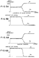
- Figures 6A and 6B respecively show the relation of the input frequencies of the detecting signals e1 and e2 to the degree of opening of the window and the relation of the amount of the adjusted reference signals x1 and x2 input into the drive control means 6 to the degree of opening of the window when the ratio changing means 42 changes the vibrator control ratio according to the degree of opening of the window.
- the ratio changing means 42 increases the input frequency of the detecting signal e1 from the acceleration sensor 32 and nullifies the input frequency of the detecting signal e2 from the microphone 2, thereby allotting all the operational power of the drive control means 6 to the control of the vibrating engine mount 36.
- the ratio changing means 42 causes the attenuators 40a and 40b to keep large the amount of the adjusted reference signal x1 input into the adaptive filter F1 irrespective of the degree of opening of the window and nullify the adjusted reference signal x2 input into the adaptive filter F2 when the degree of opening of the window becomes higher than the predetermined value.
- the microphone 2 detects the noise due to the vibration of the power unit together with the wind noise, satisfactory vibration damping effect cannot be obtained even if the speaker 4 is driven.
- the acceleration sensor 32 does not detect the wind noise, the vibration of the vehicle body 1 can be satisfactorily damped by driving the vibrating engine mount 36.
- damping of the vibration of the vehicle body 1 is preferentially effected when the degree of opening of the window exceeds the predetermined value, whereby the vibration of the vehicle body 1 can be effectively damped without increasing the operational load on the drive control means 6 and consumption of electric power can be suppressed by not driving the speaker 4, driving of which will be almost useless when the window is opened wide.
- Figures 7A and 7B respecively show the relation of the input frequencies of the detecting signals e1 and e2 to the number of the passengers and the relation of the amount of the adjusted reference signals x1 and x2 input into the drive control means 6 to the number of the passengers when the ratio changing means 42 changes the vibrator control ratio according to the number of the passengers.
- the ratio changing means 42 nullifies the input frequency of the detecting signal e1 from the acceleration sensor 32 and increases the input frequency of the detecting signal e2 from the microphone 2, thereby allotting all the operational power of the drive control means 6 to the control of the speaker 4.
- the ratio changing means 42 causes the attenuators 40a and 40b to keep large the amount of the adjusted reference signal x2 input into the adaptive filter F2 irrespective of the number of the passengers and nullify the adjusted reference signal x1 input into the adaptive filter F1 when the number of the passengers is larger than the predetermined value.
- the total weight of the vehicle increases and the level of the vibration of the vehicle body 1 due to the vibration of the engine E does not so increase even if the vibration of the engine E increases to a high level.
- the noise in the cabin caused due to the vibration of the engine E more disturbs passenger's conversation as the number of the passengers increases.
- damping of the noise in the cabin is preferentially effected when the number of the passengers exceeds the predetermined value, whereby the noise in the cabin can be effectively damped without increasing the operational load on the drive control means 6 and consumption of electric power can be suppressed by not driving the vibrating engine mount 36, driving of which will be almost useless when the number of the passengers is large.
- Figures 8A and 8B respecively show the relation of the input frequencies of the detecting signals e1 and e2 to the degree of acceleration and deceleration of the vehicle and the relation of the amount of the adjusted reference signals x1 and x2 input into the drive control means 6 to the degree of acceleration and deceleration of the vehicle when the ratio changing means 42 changes the vibrator control ratio according to the degree of acceleration and deceleration of the vehicle.
- the ratio changing means 42 increases the input frequency of the detecting signal e1 from the acceleration sensor 32 and nullifies the input frequency of the detecting signal e2 from the microphone 2, thereby allotting all the operational power of the drive control means 6 to the control of the vibrating engine mount 36.
- the ratio changing means 42 causes the attenuators 40a and 40b to keep large the amount of the adjusted reference signal x1 input into the adaptive filter F1 irrespective of the degree of acceleration and deceleration of the vehicle and nullify the adjusted reference signal x2 input into the adaptive filter F2 when the degree of acceleration and deceleration of the vehicle becomes higher than the predetermined value.
- the level of the engine vibration increases to increase the vibration of the vehicle body 1 and the noise in the cabin.
- vibration of the vehicle body 1 generally bothers the passengers but the noise in the cabin generally does not bother the passengers.
- sound of the engine during acceleration sometimes sounds comfortable for the passengers.
- damping of the vibration of the vehicle body 1 is preferentially effected when the degree of acceleration and deceleration of the vehicle exceeds the predetermined value, whereby the vibration of the vehicle body 1 can be effectively damped without increasing the operational load on the drive control means 6 and consumption of electric power can be suppressed by not driving the speaker 4, driving of which will be almost useless when the degree of acceleration and deceleration of the vehicle is large.
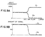
- Figures 9A and 9B respecively show the relation of the input frequencies of the detecting signals e1 and e2 to the air flow of the air-conditioner and the relation of the amount of the adjusted reference signals x1 and x2 input into the drive control means 6 to the air flow of the air-conditioner when the ratio changing means 42 changes the vibrator control ratio according to the air flow of the air-conditioner.
- the ratio changing means 42 increases the input frequency of the detecting signal e1 from the acceleration sensor 32 and nullifies the input frequency of the detecting signal e2 from the microphone 2, thereby allotting all the operational power of the drive control means 6 to the control of the vibrating engine mount 36.
- the ratio changing means 42 causes the attenuators 40a and 40b to keep large the amount of the adjusted reference signal x1 input into the adaptive filter F1 irrespective of the air flow of the air-conditioner and nullify the adjusted reference signal x2 input into the adaptive filter F2 when the air flow of the air-conditioner becomes larger than the predetermined value.
- the microphone 2 detects the noise due to the vibration of the power unit together with the noise of the-air-conditioner, satisfactory vibration damping effect cannot be obtained even if the speaker 4 is driven.
- the acceleration sensor 32 does not detect the noise of the air-conditioner, the vibration of the vehicle body 1 can be satisfactorily damped by driving the vibrating engine mount 36.
- damping of the vibration of the vehicle body 1 is preferentially effected when the air flow of the air-conditioner exceeds the predetermined value, whereby the vibration of the vehicle body 1 can be effectively damped without increasing the operational load on the drive control means 6 and consumption of electric power can be suppressed by not driving the speaker 4, driving of which will be almost useless when the air flow of the air-conditioner is large.
- Figure 10 is a flow chart for illustrating the operation of the ratio changing means 42 in changing the vibrator control ratio in this case.
- the ratio changing means 42 first determines whether the speaker 4 is in an abnormal condition. (step S1) When it is determined that the speaker 4 is in an abnormal condition, the ratio changing means 42 nullifies the input frequency of the detecting signal e2 from the microphone 2 and the adjusted reference signal x2 input into the adaptive filter F2. (step S2) After step S2 or when it is determined that the speaker 4 is not in an abnormal condition, the ratio changing means 42 determines whether the vibrating engine mount 36 is in an abnormal condition. (step S3) When it is determined that the vibrating engine mount 36 is in an abnormal condition, the ratio changing means 42 nullifies the input frequency of the detecting signal e1 from the acceleration sensor 32 and the adjusted reference signal x1 input into the adaptive filter F1. (step S4) After step S4 or when it is determined that the vibrating engine mount 36 is not in an abnormal condition, the ratio changing means 42 returns.
- the abnormal vibrator(s) is not driven and accordingly, vibration of air and/or solid elements can be prevented from being increased by driving abnormal vibrator(s). Further consumption of electric power can be suppressed by not driving abnormal vibrator(s). Further since when one of the speaker 4 and the vibrating engine mount 36 is in the abnormal state, all the operational power of the drive control means 6 is allotted to the control of the other, one of the noise in the cabin and the vibration of the vehicle body 1 can be effectively damped.
- the ratio changing means 42 may maximize the input frequency of the detecting signal e2 from the speaker 4 in addition to nullifying the input frequency of the detecting signal e1 from the acceleration sensor 32 and the adjusted reference signal x1 input into the adaptive filter F1.
- the ratio changing means 42 may maximize the input frequency of the detecting signal e1 from the acceleration sensor 32 in addition to nullifying the input frequency of the detecting signal e2 from the speaker 4 and the adjusted reference signal x2 input into the adaptive filter F2.
- FIG. 11 is a flow chart for illustrating the operation of the ratio changing means 42 in changing the vibrator control ratio in this case.
- the ratio changing means 42 first determines whether the noise level in the detecting signal e2 is higher than a predetermined level. (step T1) When it is determined that the noise level in the detecting signal e2 is higher than the predetermined level, the ratio changing means 42 nullifies the input frequency of the detecting signal e2 from the microphone 2 and the adjusted reference signal x2 input into the adaptive filter F2. (step T2) After step T2 or when it is determined that the noise level in the detecting signal e2 is not higher than the predetermined level, the ratio changing means 42 determines whether the noise level in the detecting signal e1 is higher than a predetermined level.
- step T3 When it is determined that the noise level in the detecting signal e1 is higher than the predetermined level, the ratio changing means 42 nullifies the input frequency of the detecting signal e1 from the acceleration sensor 32 and the adjusted reference signal x1 input into the adaptive filter F1.
- step T4 After step T4 or when it is determined that the noise level in the detecting signal e1 is not higher than the predetermined level, the ratio changing means 42 returns.
- the detecting signal whose noise level is high is not input and accordingly, vibration of air and/or solid elements can be prevented from being increased by driving the vibrating engine mount 36 and/or speaker 4 on the basis of detecting signal including a large amount of noise. Further consumption of electric power can be suppressed by not driving the vibrator(s) which is controlled on the basis of detecting signal including a large amount of noise. Further since when one of the detecting signals e1 and e2 includes a large amount of noise, all the operational power of the drive control means 6 is allotted to the control of the vibrator which is controlled on the basis of the other detecting signals, one of the noise in the cabin and the vibration of the vehicle body 1 can be effectively damped.
- the ratio changing means 42 may maximize the input frequency of the detecting signal e2 from the speaker 4 in addition to nullifying the input frequency of the detecting signal e1 from the acceleration sensor 32 and the adjusted reference signal x1 input into the adaptive filter F1.
- the ratio changing means 42 may maximize the input frequency of the detecting signal e1 from the acceleration sensor 32 in addition to nullifying the input frequency of the detecting signal e2 from the speaker 4 and the adjusted reference signal x2 input into the adaptive filter F2.
- Figure 12 is a flow chart for illustrating the operation of the ratio changing means 42 in changing the vibrator control ratio in this case.
- the ratio changing means 42 first determines whether the amplitude of the low frequency component of the vibration of the engine E is larger than a predetermined value. (step U1) When it is determined that the amplitude of the low frequency component of the vibration of the engine E is larger than the predetermined value, the ratio changing means 42 determines whether the amplitude of the high frequency component of the vibration of the engine E is larger than a predetermined value.
- step U2 When it is determined in step U2 that the amplitude of the high frequency component of the vibration of the engine E is not larger than the predetermined value, the ratio changing means 42 nullifies the input frequency of the detecting signal e2 from the microphone 2 and the adjusted reference signal x2 input into the adaptive filter F2 and at the same time increases the input frequency of the detecting signal e1 from the acceleration sensor 32.
- step U3 When it is determined in step U1 that the amplitude of the low frequency component of the vibration of the engine E is not larger than the predetermined value, the ratio changing means 42 determines whether the amplitude of the high frequency component of the vibration of the engine E is larger than a predetermined value.
- step U4 When it is determined in step U4 that the amplitude of the high frequency component of the vibration of the engine E is larger than the predetermined value, the ratio changing means 42 nullifies the input frequency of the detecting signal e1 from the acceleration sensor 32 and the adjusted reference signal x1 input into the adaptive filter F1 and at the same time increases the input frequency of the detecting signal e2 from the microphone 2.
- step U5 When it is determined in step U2 that the amplitude of the high frequency component of the vibration of the engine E is larger than the predetermined value or when it is determined in step U4 that the amplitude of the high frequency component of the vibration of the engine E is not larger than the predetermined value, the ratio changing means 42 returns without changing the input frequencies of the detecting signals e1 and e2 and the amounts of the adjusted reference signals x1 and x2.
- the vibration of the vehicle body 1 due to the vibration of the engine E increases when the amplitude of the low frequency component of the vibration of the engine E is large, and the noise in the cabin due to the vibration of the engine E increases when the amplitude of the high frequency component of the vibration of the engine E is large.
- the ratio changing means 42 automatically changes the vibrator control ratio according to the condition of the various factors J
- the vibration damping system of the first embodiment may be modified so that the vibrator control ratio can be manually changed.
- An example of such a modification will be described, hereinbelow.
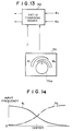
- a manual ratio setting means 70 shown in Figure 13 is provided.
- the manual ratio setting means 70 is disposed in a position where the passenger can operate it inside the cabin, e.g., on an instrument panel, and has a control dial 70a for manually setting the input frequencies.
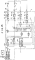
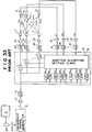
- FIG. 15 is a schematic view showing the structure of the controller employed in the vibration damping system in accordance with a second embodiment of the present invention.
- the vibration damping system of this embodiment is basically the same as the first embodiment, and accordingly the parts analogous to those in the first embodiment will be given the same reference numerals and will not be described in detail here.
- the controller C comprises a reference signal generating means 8 which generates a reference signal x on the basis of an ignition pulse signal w generated by an ignition coil 24, a drive control means 6 which generates drive signals y1 and y2 for driving the vibrating engine mount 36 and the speaker 4.
- the drive control means 6 comprises adaptive filters F1 and F2 and an adaptive algorithm section 10 which adjusts the adaptive filters F1 and F2 so that the detecting signals e1 to e2 respectively input from the acceleration sensor 32 and the microphones 2 are minimized.
- Least Mean Square Method is employed as the adaptive algorithm for adjusting the adaptive filters F1 and F2 and for this purpose, the drive control means 6 is provided with digital filters H° LM (L standing for 1, 2 and M standing for 1, 2) which are modeled on the transmission properties between the vibrating engine mount 36 and the acceleration sensor 32 and between the speaker 4 and the microphone 2.
- the controller C has a ratio changing means 42 comprising a first convergent factor changing device 51 which changes a convergent factor ⁇ 1 for the detecting signal e1 from the acceleration sensor 32, a second convergent factor changing device 52 which changes a convergent factor ⁇ 2 for the detecting signal e2 from the microphone 2, attenuators 40a and 40b which attenuates the reference signal x input from the reference signal generating means 8 by a predetermined amount, and a ratio changing section 42a which changes the attenuation rate of the reference signal x by the attenuators 40a and 40b according to the condition of a predetermined factor J of the vehicle.
- a ratio changing means 42 comprising a first convergent factor changing device 51 which changes a convergent factor ⁇ 1 for the detecting signal e1 from the acceleration sensor 32, a second convergent factor changing device 52 which changes a convergent factor ⁇ 2 for the detecting signal e2 from the microphone 2, attenuators 40
- the ratio changing means 42 changes the vibrator control ratio by changing the amounts of the adjusted reference signals x1 and x2 which are input into the drive control means 6 after passing through the attenuators 40a and 40b and the convergent factors ⁇ 1 and ⁇ 2 according to the condition of the predetermined factor J of the vehicle, thereby changing the ratio of the proportion of the output amount of the drive signal y1 to the optimal amount of the same to the proportion of the output amount of the drive signal y2 to the optimal amount of the same.
- the optimal amount of the drive signal y1 means the amount of the drive signal y1 which causes the vibrating engine mount 36 to vibrate by an amount optimal to damp the vibration of the vehicle body 1 and which is output when the amount of the adjusted reference signal x1 is of a standard value and at the same time the convergent factor ⁇ 1 is of a standard value.
- the term “the optimal amount of the drive signal y2” means the amount of the drive signal y2 which causes the speaker 4 to vibrate by an amount optimal to damp the noise in the cabin and which is output when the amount of the adjusted reference signal x2 is of a standard value and at the same time the convergent factor ⁇ 2 is of a standard value. Change of the vibrator control ratio by the ratio changing means 42 for various factors will be described, hereinbelow.
- Figures 16A to 16C respecively show the relation of the amounts of the adjusted reference signals x1 and x2 to the engine speed, the relation of the values of the convergent factors ⁇ 1 and ⁇ 2 to the engine speed when the engine speed increases from a low speed range to a high speed range, and the relation of the values of the convergent factors ⁇ 1 and ⁇ 2 to the engine speed when the engine speed decreases from the high speed range to the low speed range in the case where the ratio changing means 42 changes the vibrator control ratio according to the engine speed.
- Figures 17A to 17H show damping of the vibration of the vehicle body 1 and the noise in the cabin at 1000rpm when the vibrator control ratio is changed in the manner shown in Figures 16A to 16C, wherein Figure 17A shows the change of the vibration of the vehicle body 1, Figure 17B shows the change of the noise in the cabin, Figure 17C shows the change of the amount of the adjusted reference signal x1, Figure 17D shows the change of the amount of the adjusted reference signal x2, Figure 17E shows the change of the amount of the drive signal y1, Figure 17F shows the change of the amount of the drive signal y2, Figure 17G shows the change of the amount of the detecting signal e1, and Figure 17H shows the change of the amount of the detecting signal e2.
- Figures 18A to 18H are the views similar to Figures 17A to 17H but at 2500rpm and Figures 19A to 19H are the views similar to Figures 17A to 17H but at 4000rpm.
- the ratio changing means 42 causes the attenuators 40a and 40b to increase the amount of the adjusted reference signal x1 input into the adaptive filter F1 to the standard value (equal to the amount of the reference signal x as it is output from the amplifier 12) and reduce the adjusted reference signal x2 input into the adaptive filter F2 near zero in the low engine speed range, to gradually reduce the amount of the adjusted reference signal x1 as the engine speed increases and gradually increase the adjusted reference signal x2 as the engine speed increases in the middle engine speed range, and to reduce the adjusted reference signal x1 near zero and increase the amount of the adjusted reference signal x2 to the standard value in the high engine speed range.
- the ratio changing means 42 reduces the convergent factor ⁇ 2 for the detecting signal e2 from the microphone 2 and sets the convergent factor ⁇ 1 for the detecting signal e1 from the acceleration sensor 32 to the standard value (a value normally set taking into account the convergence to the optimal control point and the stability of control) in the low engine speed range, and the ratio changing means 42 sets the convergent factor ⁇ 2 for the detecting signal e2 to the standard value and reduces the convergent factor ⁇ 1 for the detecting signal e1 in the high engine speed range.
- the standard value a value normally set taking into account the convergence to the optimal control point and the stability of control
- the vibration damping system of this embodiment having the ratio changing means 42 which changes the vibrator control ratio in the manner described above operates as follows.
- the acceleration sensor 32 shown in Figure 15 detects the vibration of the vehicle body 1 and outputs the detecting signal e1 and the microphone 2 detects the noise in the cabin and outputs the detecting signal e2.
- the detecting signals e1 and e2 are input into the drive control means 6.
- the drive control means 6 performs calculation with calculation step widths according to the convergent factors ⁇ 1 and ⁇ 2 on the basis of the detecting signals e1 and e2 input and adjusts the adaptive filters F1 and F2.
- the ratio changing means 42 sets the convergent factor ⁇ 1 to the standard value and the convergent factor ⁇ 2 to s small value as described above. Accordingly, though adjustment of the adaptive filter F1 on the basis of the detecting signal e1 is effected in the normal manner, adjustment of the adaptive filter F2 on the basis of the detecting signal e2 is less effected. That is, when the engine speed is in the low engine speed range, damping of the vibration of the vehicle body 1 is preferentially effected.
- the ratio changing means 42 sets large the amount of the adjusted reference signal x1 input into the adaptive filter F1 and sets small the amount of the adjusted reference signal x2 input into the adaptive filter F2, the drive signal y1 for the vibrating engine mount 36 is output in the optimal amount but the drive signal y2 for the speaker 4 is output in an amount less than the optimal amount.
- the vibration of the vehicle body 1 at the acceleration sensor 32 is greatly damped but the noise in the cabin at the microphone 2 is not so damped in the low engine speed range as shown in Figures 17G and 17H.
- the vibration of the vehicle body 1 bothers the passengers more than the noise in the cabin in the low engine speed range and damping of the noise little serves to the passengers, electric power which would be consumed for driving the speaker 4 can be saved by the control described above.
- the ratio changing means 42 sets the convergent factor ⁇ 2 to the standard value and the convergent factor ⁇ 1 to s small value as described above, whereby damping of the noise in the cabin is preferentially effected. Further the drive signal y2 for the speaker 4 is output in the optimal amount but the drive signal y1 for the vibrating engine mount 36 is output in an amount less than the optimal amount. (See Figures 19C and 19D) With this arrangement, the noise in the cabin at the microphone 2 is greatly damped but the vibration of the vehicle body 1 at the acceleration sensor 32 is not so damped in the high engine speed range as shown in Figures 19G and 19H.
- the vibration of the vehicle body 1 is damped in preference to the noise in the cabin below the middle of the range near 2500rpm, and the noise in the cabin is damped in preference to the vibration of the vehicle body 1 over the middle of the range.
- the vibration of the vehicle body 1 and the noise in the cabin are damped substantially equally as can be understood from Figures 18A to 18H.
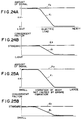
- Figures 20A and 20B respecively show the relation of the amounts of the adjusted reference signals x1 and x2 to the vehicle speed, and the relation of the values of the convergent factors ⁇ 1 and ⁇ 2 to the vehicle speed when the vibrator control ratio is changed according to the vehicle speed.
- the ratio changing means 42 causes the attenuators 40a and 40b to increase the amount of the adjusted reference signal x1 input into the adaptive filter F1 and reduce the adjusted reference signal x2 input into the adaptive filter F2 in the low engine speed range (to nullify the adjusted reference signal x2 when the vehicle speed is zero), to reduce the adjusted reference signal x1 and increase the amount of the adjusted reference signal x2 in the high engine speed range, and to increase the amount of the adjusted reference signal x1 input into the adaptive filter F1 and reduce the adjusted reference signal x2 input into the adaptive filter F2 in the highest vehicle speed range.
- the ratio changing means 42 reduces the convergent factor ⁇ 2 for the detecting signal e2 from the microphone 2 and sets the convergent factor ⁇ 1 for the detecting signal e1 from the acceleration sensor 32 to the standard value in the low vehicle speed range, sets the convergent factor ⁇ 2 for the detecting signal e2 to the standard value and reduces the convergent factor ⁇ 1 for the detecting signal e1 in the high vehicle speed range, and reduces the convergent factor ⁇ 2 for the detecting signal e2 from the microphone 2 and sets the convergent factor ⁇ 1 for the detecting signal e1 from the acceleration sensor 32 to the standard value in the highest vehicle speed range.
- the vibration of the vehicle body 1 when the vehicle speed is in the low speed range, damping of the vibration of the vehicle body 1 is preferentially effected and the drive signal y2 for the speaker 4 is output in an amount less than the optimal amount (especially when the vehicle speed is zero, the amount of the drive signal y2 for the speaker 4 is nullified).
- the vibration of the vehicle body 1 in the low vehicle speed range where the vibration of the vehicle body 1 bothers the passengers more than the noise in the cabin, the vibration of the vehicle body 1 can be effectively damped, while consumption of the electric power is suppressed by less driving the speaker 4 driving of which little serves to the passengers.
- damping of the noise in the cabin is preferentially effected and the drive signal y1 for the vibrating engine mount 36 is output in an amount less than the optimal amount.
- the noise in the cabin bothers the passengers more than the vibration of the vehicle body 1
- the noise in the cabin can be effectively damped, while consumption of the electric power is suppressed by less driving the vibrating engine mount 36 driving of which little serves to the passengers.
- damping of the vibration of the vehicle body 1 is preferentially effected and the drive signal y2 for the speaker 4 is output in an amount less than the optimal amount.
- Figures 21A to 21C respecively show the relation of the amounts of the adjusted reference signals x1 and x2 to the engine load, the relation of the values of the convergent factors ⁇ 1 and ⁇ 2 to the engine load when the engine load increases, and the relation of the values of the convergent factors ⁇ 1 and ⁇ 2 to the engine load when the engine load decreases in the case where the ratio changing means 42 changes the vibrator control ratio according to the engine load.
- the ratio changing means 42 causes the attenuators 40a and 40b to increase the amount of the adjusted reference signal x1 input into the adaptive filter F1 and reduce the adjusted reference signal x2 input into the adaptive filter F2 when the engine load exceeds a first predetermined value, and to reduce the adjusted reference signal x1 and increase the amount of the adjusted reference signal x2 when the engine load exceeds a second predetermined value.
- the ratio changing means 42 reduces the convergent factor ⁇ 2 for the detecting signal e2 from the microphone 2 and sets the convergent factor ⁇ 1 for the detecting signal e1 from the acceleration sensor 32 to the standard value when the engine load exceeds the first predetermined value, and the ratio changing means 42 sets the convergent factor ⁇ 2 for the detecting signal e2 to the standard value and reduces the convergent factor ⁇ 1 for the detecting signal e1 when the engine load exceeds the second predetermined value.
- Figures 22A and 22B respecively show the relation of the amounts of the adjusted reference signals x1 and x2 to the loudness of the audio system, and the relation of the values of the convergent factors ⁇ 1 and ⁇ 2 to the loudness of the audio system in the case where the ratio changing means 42 changes the vibrator control ratio according to the loudness of the audio system.
- the ratio changing means 42 causes the attenuators 40a and 40b to increase the amount of the adjusted reference signal x1 input into the adaptive filter F1 and reduce the adjusted reference signal x2 input into the adaptive filter F2 when the loudness of the audio system exceeds a predetermined value.
- the ratio changing means 42 reduces the convergent factor ⁇ 2 for the detecting signal e2 from the microphone 2 and sets the convergent factor ⁇ 1 for the detecting signal e1 from the acceleration sensor 32 to the standard value when the loudness of the audio system exceeds the predetermined value.
- Figures 23A and 23B respecively show the relation of the amounts of the adjusted reference signals x1 and x2 to the degree of charge of the battery, and the relation of the values of the convergent factors ⁇ 1 and ⁇ 2 to the degree of charge of the battery in the case where the ratio changing means 42 changes the vibrator control ratio according to the degree of charge of the battery.
- the ratio changing means 42 causes the attenuators 40a and 40b to reduce the amount of the adjusted reference signal x1 input into the adaptive filter F1 when the degree of charge of the battery is lower than a predetermined value while keeping the amount of the adjusted reference signal x2 input into the adaptive filter F2 large irrespective of the degree of charge of the battery.
- the ratio changing means 42 reduces the convergent factor ⁇ 1 for the detecting signal e1 from the acceleration sensor 32 when the degree of charge of the battery is lower than the predetermined value while keeping the convergent factor ⁇ 2 for the detecting signal e2 from the microphone 2 at the standard value irrespective of the degree of charge of the battery.
- the drive signal y1 for the vibrating engine mount 36 is output in an amount less than the optimal amount.
- the vibrating engine mount 36 consumes electric power more than the speaker 4, and accordingly, the vibrating engine mount 36 is less driven until the degree of charge of the battery is improved.
- Figures 24A and 24B respecively show the relation of the amounts of the adjusted reference signals x1 and x2 to the electric load, and the relation of the values of the convergent factors ⁇ 1 and ⁇ 2 to the electric load in the case where the ratio changing means 42 changes the vibrator control ratio according to the electric load.
- the ratio changing means 42 causes the attenuators 40a and 40b to reduce the amount of the adjusted reference signal x1 input into the adaptive filter F1 when the electric load exceeds a predetermined value while keeping the amount of the adjusted reference signal x2 input into the adaptive filter F2 large irrespective of the electric load.
- the ratio changing means 42 reduces the convergent factor ⁇ 1 for the detecting signal e1 from the acceleration sensor 32 when the electric load exceeds the predetermined value while keeping the convergent factor ⁇ 2 for the detecting signal e2 from the microphone 2 at the standard value irrespective of the electric load.
- the drive signal y1 for the vibrating engine mount 36 is output in an amount less than the optimal amount.
- the vibrating engine mount 36 consumes electric power more than the speaker 4, and accordingly, the vibrating engine mount 36 is less driven in order to reduce the electric load.
- the predetermined factor J is the vibration of the vehicle body 1 which is not caused by the vibration of the engine
- the ratio changing means 42 changes the vibrator control ratio according to the vibration of the vehicle body 1 which is not caused by the vibration of the engine
- Figures 25A and 25B respecively show the relation of the amounts of the adjusted reference signals x1 and x2 to the vibration of the vehicle body 1 which is not caused by the vibration of the engine, and the relation of the values of the convergent factors ⁇ 1 and ⁇ 2 to the vibration of the vehicle body 1 which is not caused by the vibration of the engine in the case where the ratio changing means 42 changes the vibrator control ratio according to the vibration of the vehicle body 1 which is not caused by the vibration of the engine.
- the ratio changing means 42 causes the attenuators 40a and 40b to reduce the amount of the adjusted reference signal x1 input into the adaptive filter F1 and increase the adjusted reference signal x2 input into the adaptive filter F2 when the vibration of the vehicle body 1 which is not caused by the vibration of the engine exceeds a predetermined level.
- the ratio changing means 42 reduces the convergent factor ⁇ 1 for the detecting signal e1 from the acceleration sensor 32 and sets the convergent factor ⁇ 2 for the detecting signal e2 from the microphone 2 to the standard value when the vibration of the vehicle body 1 which is not caused by the vibration of the engine exceeds a predetermined level.
- FIG. 26 is a schematic view showing the structure of the controller employed in the vibration damping system in accordance with a third embodiment of the present invention.
- the vibration damping system of this embodiment is basically the same as the first embodiment, and accordingly the parts analogous to those in the first embodiment will be given the same reference numerals and will not be described in detail here.
- the controller C comprises a reference signal generating means 8 which generates a reference signal x on the basis of an ignition pulse signal w generated by an ignition coil 24, a drive control means 6 which generates a drive signal y0 for driving the vibrating engine mount 36 and the speaker 4 on the basis of the reference signal x.
- the controller C further comprises a drive signal separator 142 which separates the drive signal y0 generated by the drive control means 6 into a low frequency drive signal y1 and a high frequency drive signal y2 and a detecting signal mixer 144 which mixes the detecting signal e1 from the acceleration sensor 32 and the detecting signal e2 from the microphone 2 into a detecting signal e0.
- controller C has therein an amplifier 12 which amplifies the reference signal x, an A/D convertor 14 which converts the reference signal x into a digital signal, a D/A convertor 20 which converts the drive signal y0 into an analog signal and an A/D convertor 18 which converts the detecting signal e0 into a digital signal.
- the vibration damping system of this embodiment is characterized in that the controller C has the drive signal separator 142 and the detecting signal mixer 144. This point will be described in detail, hereinbelow.
- one acceleration sensor 32 and one microphone 2 form a vibration sensor group 146 and one vibrating engine mount 36 and one speaker 4 form a vibrator group 148.
- the acceleration sensor 32 detects the vibration of the vehicle body 1 and outputs the detecting signal e1 and the microphone 2 detects the noise in the cabin and outputs the detecting signal e2.
- the detecting signals e1 and e2 are input into the detecting signal mixer 144 in the controller C.
- the detecting signal mixer 144 comprises amplifiers 16 which amplify the detecting signals e1 and e2, a band pass filter 150 which transmits only a component in a predetermined high frequency band of the detecting signal e2 from the microphone 2, and a low pass filter 152 which transmits a component having a frequency lower than a predetermined frequency of the detecting signal e1 from the acceleration sensor 32.
- the frequency band which the band pass filter 150 transmits does not overlap the frequency band which the low pass filter 152 transmits.
- the high frequency detecting signal e2' passing through the band pass filter 150 and the low frequency detecting signal e1' passing through the low pass filter 152 are mixed together into a detecting signal e0, which is input into the drive control means 6.
- the drive control means 6 comprises an adaptive filter F which adjusts every moment the phase and the amplitude of the reference signal x and an adaptive algorithm section 10 which adjusts the adaptive filter F so that the detecting signal e0 input from the detecting signal mixer 144 is minimized.
- Least Mean Square Method is employed as the adaptive algorithm for adjusting the adaptive filter F and for this purpose, the drive control means 6 is provided with digital filters H° LM (L standing for 1, 2 and M standing for 1, 2) which are modeled on the transmission properties between the vibrating engine mount 36 and the acceleration sensor 32 and between the speaker 4 and the microphone 2.
- the drive control means 6 performs calculation on the basis of the detecting signal e0 input from the detecting signal mixer 144 and adjusts the adaptive filter F every moment, thereby generating a drive signal y0 for driving the vibrating engine mount 36 and the speaker 4.
- the drive signal y0 generated by the drive control means 6 is input into the drive signal separator 142 and is separated into a low frequency drive signal y1 for driving the vibrating engine mount 36 and a high frequency drive signal y2 for driving the speaker 4.
- the drive signal separator 142 comprises a band pass filter 150 which transmits only a component in a predetermined high frequency band of the drive signal y0, and a low pass filter 152 which transmits a component having a frequency lower than a predetermined frequency of the drive signal y0, and amplifiers 22 which amplify the signals passing through the respective filters 150 and 152, and outputs a low frequency drive signal y1 and a high frequency drive signal y2 by separating the drive signal y0.
- the vibrating engine mount 36 and the speaker 4 which form the vibrator group 148 are respectively drive by the low frequency drive signal y1 and the high frequency drive signal y2 to damp the vibration of the vehicle body 1 and the noise in the cabin.
- the vibration of the vehicle body 1 and the noise in the cabin can be effectively damped without increasing the operational load on the drive control means 6.
- the drive signal separator 142 may be formed of an electric circuit having a capacitor and/or a winding. Modifications of the drive signal separator 142 are shown in Figures 27, 29 and 31.
- Figure 27 is a circuit diagram showing a modification of the drive signal separator 142
- Figure 28 is a view showing the frequency separation properties of the circuit shown in Figure 27.
- Figure 29 is a circuit diagram showing another modification of the drive signal separator 142
- Figure 30 is a view showing the frequency separation properties of the circuit shown in Figure 29.
- Figure 31 is a circuit diagram showing still another modification of the drive signal separator 142
- Figure 32 is a view showing the frequency separation properties of the circuit shown in Figure 31.
- the vibration damping system in accordance with the present invention may be variously modified without limiting to the embodiments described above. Further, though, in the embodiments described above, an optimization technique (LMS) is employed in the calculation performed by the drive control means, the present invention can also be applied to the vibration damping system having a drive control means which performs calculation without using an optimization technique.
- LMS optimization technique
Landscapes
- Engineering & Computer Science (AREA)
- Physics & Mathematics (AREA)
- Acoustics & Sound (AREA)
- Multimedia (AREA)
- Mechanical Engineering (AREA)
- General Engineering & Computer Science (AREA)
- Aviation & Aerospace Engineering (AREA)
- Chemical & Material Sciences (AREA)
- Combustion & Propulsion (AREA)
- Transportation (AREA)
- General Physics & Mathematics (AREA)
- Vibration Prevention Devices (AREA)
- Soundproofing, Sound Blocking, And Sound Damping (AREA)
- Arrangement Or Mounting Of Propulsion Units For Vehicles (AREA)
- Fittings On The Vehicle Exterior For Carrying Loads, And Devices For Holding Or Mounting Articles (AREA)
Applications Claiming Priority (9)
| Application Number | Priority Date | Filing Date | Title |
|---|---|---|---|
| JP230749/92 | 1992-08-31 | ||
| JP23074992 | 1992-08-31 | ||
| JP23074992 | 1992-08-31 | ||
| JP23816992 | 1992-09-07 | ||
| JP238169/92 | 1992-09-07 | ||
| JP23816992 | 1992-09-07 | ||
| JP19574493A JP3276214B2 (ja) | 1992-08-31 | 1993-08-06 | 車両の振動低減装置 |
| JP19574493 | 1993-08-06 | ||
| JP195744/93 | 1993-08-06 |
Publications (3)
| Publication Number | Publication Date |
|---|---|
| EP0585875A2 true EP0585875A2 (de) | 1994-03-09 |
| EP0585875A3 EP0585875A3 (de) | 1995-08-02 |
| EP0585875B1 EP0585875B1 (de) | 2000-03-22 |
Family
ID=27327140
Family Applications (1)
| Application Number | Title | Priority Date | Filing Date |
|---|---|---|---|
| EP93113903A Expired - Lifetime EP0585875B1 (de) | 1992-08-31 | 1993-08-31 | Kraftwagenvibrationsdampfungsanordnung |
Country Status (6)
| Country | Link |
|---|---|
| US (1) | US5617315A (de) |
| EP (1) | EP0585875B1 (de) |
| JP (1) | JP3276214B2 (de) |
| KR (1) | KR0140753B1 (de) |
| CN (1) | CN1043807C (de) |
| DE (1) | DE69328148T2 (de) |
Cited By (3)
| Publication number | Priority date | Publication date | Assignee | Title |
|---|---|---|---|---|
| GB2305328A (en) * | 1995-08-26 | 1997-04-02 | Fichtel & Sachs Ag | Controlling vibrations in a passenger compartment of a motor vehicle and detecting dfects in a motor vehicle |
| EP0840285A3 (de) * | 1996-11-04 | 1999-05-12 | Tenneco Automotive Inc. | Aktiver Lärmkonditionierungsanordnung |
| US6572178B2 (en) | 2001-03-16 | 2003-06-03 | Benteler Automobiltechnik Gmbh & Co. Kg | Dashboard support with vibration-damping feature |
Families Citing this family (26)
| Publication number | Priority date | Publication date | Assignee | Title |
|---|---|---|---|---|
| JPH09280307A (ja) * | 1996-04-10 | 1997-10-28 | Nissan Motor Co Ltd | 車両用能動型振動制御装置 |
| US7305094B2 (en) * | 2001-01-12 | 2007-12-04 | University Of Dayton | System and method for actively damping boom noise in a vibro-acoustic enclosure |
| US20020136415A1 (en) * | 2001-03-20 | 2002-09-26 | Siemens Vdo Automotive, Inc. | Active noise cancellation for a vehicle induction system with selectable modelling noise |
| US7106867B2 (en) * | 2001-05-08 | 2006-09-12 | Siemens Vdo Automotive Inc. | Active noise cancellation for a vehicle induction system having selectable engine noise profile |
| US20030215101A1 (en) * | 2002-05-15 | 2003-11-20 | Siemens Vdo Automotive, Inc. | Active noise control system with an elongated transmission member |
| US7231052B2 (en) * | 2002-07-18 | 2007-06-12 | Honda Giken Kogyo Kabushiki Kaisha | Vibration-isolating and sound isolating system for vehicle |
| JP4958154B2 (ja) * | 2006-11-29 | 2012-06-20 | 本田技研工業株式会社 | 自動二輪車 |
| DE102007019365B4 (de) * | 2007-04-23 | 2013-04-11 | Grammer Aktiengesellschaft | Verfahren und Vorrichtung zur Auswertung von auf eine Person wirkenden Schwingungen eines Fahrzeuges |
| DE102007019366B4 (de) * | 2007-04-23 | 2016-12-15 | Grammer Ag | Vorrichtung und Verfahren zur Erfassung von auf eine Person übertragene Schwingungen eines Fahrzeuges |
| US8800736B2 (en) * | 2008-05-30 | 2014-08-12 | Design, Imaging & Control, Inc. | Adjustable tuned mass damper systems |
| JP2011109222A (ja) * | 2009-11-13 | 2011-06-02 | Sinfonia Technology Co Ltd | A/d変換装置、制振装置及びこれらを搭載した車両 |
| KR20120114214A (ko) * | 2009-11-25 | 2012-10-16 | 신포니아 테크놀로지 가부시끼가이샤 | 제진 장치 및 이것을 구비한 차량 |
| US8752394B2 (en) * | 2010-03-15 | 2014-06-17 | Rolls-Royce Corporation | Determining fan parameters through pressure monitoring |
| KR20110108756A (ko) * | 2010-03-29 | 2011-10-06 | 윤경원 | 다모드 시스템에서 잔류진동 제거 방법 |
| JP5713958B2 (ja) * | 2012-05-22 | 2015-05-07 | 本田技研工業株式会社 | 能動型騒音制御装置 |
| CN103578460A (zh) * | 2012-07-19 | 2014-02-12 | 徐丰辰 | 一种车辆阻尼降噪方法 |
| JP5822862B2 (ja) * | 2013-03-21 | 2015-11-25 | 本田技研工業株式会社 | 車両用能動型振動騒音制御装置 |
| KR101628119B1 (ko) * | 2014-08-11 | 2016-06-08 | 현대자동차 주식회사 | 소음제어시스템 및 그 방법 |
| US9729961B2 (en) * | 2014-11-25 | 2017-08-08 | Bose Corporation | Actively suspended seat with bass loudspeakers |
| CN105042828B (zh) * | 2015-08-14 | 2018-06-29 | 珠海格力电器股份有限公司 | 一种减振装置及其控制方法 |
| KR102486178B1 (ko) * | 2018-10-30 | 2023-01-10 | 현대자동차주식회사 | 차량 및 그 제어 방법 |
| JP7251385B2 (ja) * | 2019-07-30 | 2023-04-04 | セイコーエプソン株式会社 | 振動デバイス、電子機器および移動体 |
| US11377041B2 (en) * | 2019-08-06 | 2022-07-05 | Bose Corporation | Pressure control in externally ducted loudspeakers |
| US12330566B2 (en) | 2019-08-06 | 2025-06-17 | Dr. Ing. H.C. F. Porsche Aktiengesellschaft | Pressure control in externally ducted loudspeakers |
| US11333547B2 (en) * | 2019-10-25 | 2022-05-17 | Blackberry Limited | Method and system for shipping container loading and unloading estimation |
| FR3108178B1 (fr) * | 2020-03-11 | 2024-03-15 | Vitesco Technologies | Dispositif de gestion des vibrations d’un vehicule automobile et procede associe |
Family Cites Families (12)
| Publication number | Priority date | Publication date | Assignee | Title |
|---|---|---|---|---|
| JPS5717027A (en) * | 1980-07-03 | 1982-01-28 | Hitachi Ltd | Vibration reducing device of electric machinery |
| GB8615315D0 (en) * | 1986-06-23 | 1986-07-30 | Secr Defence | Aircraft cabin noise control apparatus |
| GB2203016A (en) * | 1986-10-07 | 1988-10-05 | Adaptive Control Ltd | Active sound control apparatus |
| DE3786165T2 (de) * | 1986-10-07 | 1993-10-14 | Adaptive Control Ltd | Aktive vibrationskontrolle. |
| JPH0495634A (ja) * | 1990-08-13 | 1992-03-27 | Toyota Motor Corp | 車両振動低減装置 |
| US5233540A (en) * | 1990-08-30 | 1993-08-03 | The Boeing Company | Method and apparatus for actively reducing repetitive vibrations |
| JPH04113946A (ja) * | 1990-09-04 | 1992-04-15 | Nissan Motor Co Ltd | 自動車の騒音制御装置 |
| US5146505A (en) * | 1990-10-04 | 1992-09-08 | General Motors Corporation | Method for actively attenuating engine generated noise |
| GB2252657A (en) * | 1990-10-24 | 1992-08-12 | Lotus Car | Vibration and sound generation in vehicles |
| US5245552A (en) * | 1990-10-31 | 1993-09-14 | The Boeing Company | Method and apparatus for actively reducing multiple-source repetitive vibrations |
| JPH04210141A (ja) * | 1990-11-30 | 1992-07-31 | Toyoda Gosei Co Ltd | 防振装置 |
| US5148402A (en) * | 1990-12-21 | 1992-09-15 | United Technologies Corporation | Method for reducing aircraft cabin noise and vibration |
-
1993
- 1993-08-06 JP JP19574493A patent/JP3276214B2/ja not_active Expired - Fee Related
- 1993-08-25 US US08/111,470 patent/US5617315A/en not_active Expired - Fee Related
- 1993-08-30 KR KR1019930016998A patent/KR0140753B1/ko not_active Expired - Fee Related
- 1993-08-31 DE DE69328148T patent/DE69328148T2/de not_active Expired - Fee Related
- 1993-08-31 EP EP93113903A patent/EP0585875B1/de not_active Expired - Lifetime
- 1993-08-31 CN CN93118825A patent/CN1043807C/zh not_active Expired - Fee Related
Cited By (4)
| Publication number | Priority date | Publication date | Assignee | Title |
|---|---|---|---|---|
| GB2305328A (en) * | 1995-08-26 | 1997-04-02 | Fichtel & Sachs Ag | Controlling vibrations in a passenger compartment of a motor vehicle and detecting dfects in a motor vehicle |
| US5748748A (en) * | 1995-08-26 | 1998-05-05 | Fichtel & Sachs Ag | Apparatus and method for influencing oscillations in the passenger compartment of a motor vehicle and apparatus and method for detecting defects in a motor vehicle |
| EP0840285A3 (de) * | 1996-11-04 | 1999-05-12 | Tenneco Automotive Inc. | Aktiver Lärmkonditionierungsanordnung |
| US6572178B2 (en) | 2001-03-16 | 2003-06-03 | Benteler Automobiltechnik Gmbh & Co. Kg | Dashboard support with vibration-damping feature |
Also Published As
| Publication number | Publication date |
|---|---|
| JPH06127276A (ja) | 1994-05-10 |
| DE69328148D1 (de) | 2000-04-27 |
| KR0140753B1 (ko) | 1998-07-01 |
| EP0585875B1 (de) | 2000-03-22 |
| US5617315A (en) | 1997-04-01 |
| KR940003761A (ko) | 1994-03-12 |
| DE69328148T2 (de) | 2000-11-16 |
| JP3276214B2 (ja) | 2002-04-22 |
| CN1089016A (zh) | 1994-07-06 |
| EP0585875A3 (de) | 1995-08-02 |
| CN1043807C (zh) | 1999-06-23 |
Similar Documents
| Publication | Publication Date | Title |
|---|---|---|
| US5617315A (en) | Active vibration damping system for a vehicle | |
| US5651072A (en) | Vibration damping system for vehicle | |
| JP2748626B2 (ja) | 能動型騒音制御装置 | |
| EP0795169B1 (de) | Frequenzfokussierte schwinggeber für aktive systeme zur schwingungsenergie-minderung | |
| US5526292A (en) | Broadband noise and vibration reduction | |
| KR102408323B1 (ko) | 엔진 소음 상쇄를 위한 가상 위치 노이즈 신호 추정 | |
| EP2667380B1 (de) | Aktive Rauschsteuerungsvorrichtung | |
| US9729961B2 (en) | Actively suspended seat with bass loudspeakers | |
| EP0631383A2 (de) | Akustisches Wiedergabesystem | |
| US5690321A (en) | Vibration damping system for vehicle | |
| JP2529745B2 (ja) | 能動型騒音制御装置 | |
| JP3742702B2 (ja) | 能動振動抑制装置 | |
| JPH06118970A (ja) | 騒音キャンセル装置 | |
| JP2674251B2 (ja) | 能動型騒音制御装置 | |
| CA2356222A1 (en) | Noise reduction apparatus | |
| JP3502112B2 (ja) | 騒音キャンセル装置 | |
| JP3612734B2 (ja) | 車両騒音低減装置及び制御信号設定方法 | |
| JP3612736B2 (ja) | 車両騒音低減装置及び制御信号設定方法 | |
| JPH06266371A (ja) | 車両のアクティブ騒音制御装置 | |
| JP3278185B2 (ja) | 車両用騒音制御装置 | |
| JP2748734B2 (ja) | 能動型騒音制御装置 | |
| JPH064085A (ja) | 車両の能動型騒音低減装置 | |
| JPH056186A (ja) | 車両用騒音制御装置 | |
| US20040175004A1 (en) | Error signal processing to reduce spectral overlap in an active noise control system | |
| JPH06153288A (ja) | 車載用音響再生システム |
Legal Events
| Date | Code | Title | Description |
|---|---|---|---|
| PUAI | Public reference made under article 153(3) epc to a published international application that has entered the european phase |
Free format text: ORIGINAL CODE: 0009012 |
|
| AK | Designated contracting states |
Kind code of ref document: A2 Designated state(s): DE FR GB |
|
| PUAL | Search report despatched |
Free format text: ORIGINAL CODE: 0009013 |
|
| AK | Designated contracting states |
Kind code of ref document: A3 Designated state(s): DE FR GB |
|
| 17P | Request for examination filed |
Effective date: 19960125 |
|
| 17Q | First examination report despatched |
Effective date: 19981127 |
|
| GRAG | Despatch of communication of intention to grant |
Free format text: ORIGINAL CODE: EPIDOS AGRA |
|
| GRAG | Despatch of communication of intention to grant |
Free format text: ORIGINAL CODE: EPIDOS AGRA |
|
| GRAH | Despatch of communication of intention to grant a patent |
Free format text: ORIGINAL CODE: EPIDOS IGRA |
|
| GRAH | Despatch of communication of intention to grant a patent |
Free format text: ORIGINAL CODE: EPIDOS IGRA |
|
| GRAA | (expected) grant |
Free format text: ORIGINAL CODE: 0009210 |
|
| AK | Designated contracting states |
Kind code of ref document: B1 Designated state(s): DE FR GB |
|
| REF | Corresponds to: |
Ref document number: 69328148 Country of ref document: DE Date of ref document: 20000427 |
|
| ET | Fr: translation filed | ||
| PLBE | No opposition filed within time limit |
Free format text: ORIGINAL CODE: 0009261 |
|
| 26N | No opposition filed | ||
| REG | Reference to a national code |
Ref country code: GB Ref legal event code: IF02 |
|
| PGFP | Annual fee paid to national office [announced via postgrant information from national office to epo] |
Ref country code: FR Payment date: 20020808 Year of fee payment: 10 |
|
| PGFP | Annual fee paid to national office [announced via postgrant information from national office to epo] |
Ref country code: GB Payment date: 20020828 Year of fee payment: 10 |
|
| PG25 | Lapsed in a contracting state [announced via postgrant information from national office to epo] |
Ref country code: GB Free format text: LAPSE BECAUSE OF NON-PAYMENT OF DUE FEES Effective date: 20030831 |
|
| PGFP | Annual fee paid to national office [announced via postgrant information from national office to epo] |
Ref country code: DE Payment date: 20030911 Year of fee payment: 11 |
|
| GBPC | Gb: european patent ceased through non-payment of renewal fee | ||
| PG25 | Lapsed in a contracting state [announced via postgrant information from national office to epo] |
Ref country code: FR Free format text: LAPSE BECAUSE OF NON-PAYMENT OF DUE FEES Effective date: 20040430 |
|
| REG | Reference to a national code |
Ref country code: FR Ref legal event code: ST |
|
| PG25 | Lapsed in a contracting state [announced via postgrant information from national office to epo] |
Ref country code: DE Free format text: LAPSE BECAUSE OF NON-PAYMENT OF DUE FEES Effective date: 20050301 |