EP0585888A2 - Dispositif de détection de la position et de verrouillage du chariot "pour un appareil d'enregistrement" - Google Patents
Dispositif de détection de la position et de verrouillage du chariot "pour un appareil d'enregistrement" Download PDFInfo
- Publication number
- EP0585888A2 EP0585888A2 EP93113931A EP93113931A EP0585888A2 EP 0585888 A2 EP0585888 A2 EP 0585888A2 EP 93113931 A EP93113931 A EP 93113931A EP 93113931 A EP93113931 A EP 93113931A EP 0585888 A2 EP0585888 A2 EP 0585888A2
- Authority
- EP
- European Patent Office
- Prior art keywords
- carriage
- recording
- recording apparatus
- fixing
- ink
- Prior art date
- Legal status (The legal status is an assumption and is not a legal conclusion. Google has not performed a legal analysis and makes no representation as to the accuracy of the status listed.)
- Granted
Links
Images











Classifications
-
- B—PERFORMING OPERATIONS; TRANSPORTING
- B41—PRINTING; LINING MACHINES; TYPEWRITERS; STAMPS
- B41J—TYPEWRITERS; SELECTIVE PRINTING MECHANISMS, i.e. MECHANISMS PRINTING OTHERWISE THAN FROM A FORME; CORRECTION OF TYPOGRAPHICAL ERRORS
- B41J25/00—Actions or mechanisms not otherwise provided for
- B41J25/304—Bodily-movable mechanisms for print heads or carriages movable towards or from paper surface
- B41J25/312—Bodily-movable mechanisms for print heads or carriages movable towards or from paper surface with print pressure adjustment mechanisms, e.g. pressure-on-the paper mechanisms
-
- B—PERFORMING OPERATIONS; TRANSPORTING
- B41—PRINTING; LINING MACHINES; TYPEWRITERS; STAMPS
- B41J—TYPEWRITERS; SELECTIVE PRINTING MECHANISMS, i.e. MECHANISMS PRINTING OTHERWISE THAN FROM A FORME; CORRECTION OF TYPOGRAPHICAL ERRORS
- B41J2/00—Typewriters or selective printing mechanisms characterised by the printing or marking process for which they are designed
- B41J2/005—Typewriters or selective printing mechanisms characterised by the printing or marking process for which they are designed characterised by bringing liquid or particles selectively into contact with a printing material
- B41J2/01—Ink jet
- B41J2/135—Nozzles
- B41J2/165—Prevention or detection of nozzle clogging, e.g. cleaning, capping or moistening for nozzles
- B41J2/16505—Caps, spittoons or covers for cleaning or preventing drying out
- B41J2/16508—Caps, spittoons or covers for cleaning or preventing drying out connected with the printer frame
- B41J2/16511—Constructions for cap positioning
-
- B—PERFORMING OPERATIONS; TRANSPORTING
- B41—PRINTING; LINING MACHINES; TYPEWRITERS; STAMPS
- B41J—TYPEWRITERS; SELECTIVE PRINTING MECHANISMS, i.e. MECHANISMS PRINTING OTHERWISE THAN FROM A FORME; CORRECTION OF TYPOGRAPHICAL ERRORS
- B41J2/00—Typewriters or selective printing mechanisms characterised by the printing or marking process for which they are designed
- B41J2/005—Typewriters or selective printing mechanisms characterised by the printing or marking process for which they are designed characterised by bringing liquid or particles selectively into contact with a printing material
- B41J2/01—Ink jet
- B41J2/135—Nozzles
- B41J2/165—Prevention or detection of nozzle clogging, e.g. cleaning, capping or moistening for nozzles
- B41J2/16505—Caps, spittoons or covers for cleaning or preventing drying out
- B41J2/16508—Caps, spittoons or covers for cleaning or preventing drying out connected with the printer frame
-
- B—PERFORMING OPERATIONS; TRANSPORTING
- B41—PRINTING; LINING MACHINES; TYPEWRITERS; STAMPS
- B41J—TYPEWRITERS; SELECTIVE PRINTING MECHANISMS, i.e. MECHANISMS PRINTING OTHERWISE THAN FROM A FORME; CORRECTION OF TYPOGRAPHICAL ERRORS
- B41J2/00—Typewriters or selective printing mechanisms characterised by the printing or marking process for which they are designed
- B41J2/005—Typewriters or selective printing mechanisms characterised by the printing or marking process for which they are designed characterised by bringing liquid or particles selectively into contact with a printing material
- B41J2/01—Ink jet
- B41J2/21—Ink jet for multi-colour printing
Definitions
- the present invention relates to a recording apparatus of such a structure that recording means is mounted on a carriage which travels along a recording medium to record images on it by use of the recording means.
- a recording apparatus having the functions of a printer, copying machine, facsimile, and the like or a recording apparatus used as an output device for a complex type electronic equipment or a work station including a computer, word processor, and others, is structured so that images are recorded on a recording material (recording medium) such as a paper sheet and a thin plastic sheet in accordance with image information.
- a recording material such as a paper sheet and a thin plastic sheet in accordance with image information.
- These recording apparatuses can be classified as an ink jet type, a wire dot type, a thermal type, a laser beam type, and some others according to the recording methods to be adopted.
- a serial type recording apparatus which employs a serial scan method whereby to execute its main scanning in the direction orthogonal to the feeding direction (sub-scanning direction) of a recording material, the recording material is set at a given recording position; images are recorded (main scanned) by the use of recording means mounted on a carriage which travels along the recording material; subsequent to the completion of a one-line recording, the sheet is fed by a given amount (pitch feeding); then, the next line recording (main scanning) is executed on the recording material which has come to a stop again; thus, by repeating this sequence of operations, the entire recording on the recording material will be executed.
- the recording material is set at a given recording position; subsequent to the completion of a one-line recording collectively, the sheet is fed by a given amount (pitch feeding); then, by repeating the operations of executing the next line recording collectively, the entire recording on the recording material will be executed.
- the ink jet type recording apparatus is such that ink is discharged from recording means (recording head) onto a recording material for recording.
- recording means recording head
- recording means recording head
- this type it is possible to make the recording means compact and record highly precise images at a high speed. It is also possible to record on an ordinary sheet without any particular treatments given to it, thus providing the inexpensive running cost. Having no impact, this type generates less noises. Also, among other advantages, this type of recording allows many different colors of ink to be used easily for recording color images.
- the one having the arrangement of a highly densified liquid passages can be manufactured easily by forming the filmed electrothermal transducers, electrodes, liquid passage walls, a ceiling plate, and others on a substrate through the etching, vapor deposition, sputtering, and other semiconductor fabrication processes. It is thus possible to implement the provision of a more compact recording means.
- the forces exerted by such operations and others will affect the carriage to bend the carriage or the guide rails, making it difficult to execute the operations and others exactly or to cause the distance between the recording means mounted on the carriage and the platen to be varied inevitably. Then, the recording quality may be lowered. Particularly, in an ink jet recording apparatus, the variations of the space between the recording medium placed on its platen and ink jet recording head will produce adverse effects on the recording quality.
- an ink jet recording apparatus if its ink jet recording head cannot be located exactly in a position for capping or the carriage guide rails are bent, a problem is encountered in carrying out the capping for the head appropriately.
- the fixing method for the carriage in the main scanning direction has hitherto been such that the carriage is fixed manually when it is not in use or the carriage is brought to a stop position by an electrical system using a stepper motor among some others.
- a recording apparatus which is provided with a manual carriage locking mechanism as another fixing method.
- the scanning is executed along the carriage guiding shafts arranged in parallel with the carriage platen, and when the recording apparatus is not in use, the carriage locking button which is provided for the recording apparatus is operated manually in order to fix the carriage so that it will not move in the scanning direction with respect to the carriage guiding shafts.
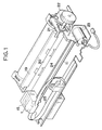
- Fig. 1 is a perspective view schematically illustrating the entire structure of a recording apparatus as an embodiment according to the present invention.
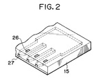
- Fig. 2 is a perspective view schematically illustrated a recording head shown in Fig. 1.
- Fig. 3 is a block diagram showing the control of a recording apparatus as an embodiment according to the present invention.
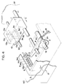
- Fig. 4 is a perspective view schematically illustrating a carriage, a recovery unit, and others according to a first embodiment of the recording apparatus of the present invention.
- Fig. 5 is a vertically sectional view schematically showing those elements in Fig. 4 observed in the direction indicated by an arrow A.
- Fig. 6 is a block diagram showing the driving control of the cam illustrated in Fig. 4 and Fig. 5.
- Fig. 7 is a vertically sectional view schematically showing a variation of the carriage fixing unit according to the first embodiment.
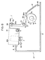
- Fig. 8 is a vertically sectional view schematically showing a second embodiment of the carriage, recovery unit, and others according to the present invention.
- Fig. 9 is a schematic view showing the carriage fixing unit in Fig. 8 observed in the direction indicated by an arrow F.
- Fig. 10 is a vertically sectional view schematically showing a third embodiment of the carriage, recovery unit, and others according to the present invention.
- Fig. 11 is a schematic view showing the carriage fixing unit in Fig. 10 observed in the direction indicated by an arrow G.
- Fig. 12 is a perspective view schematically showing the carriage, recovery unit, and others according to a fourth embodiment of the recording apparatus of the present invention.
- Fig. 13 is a detailed view schematically illustrating the fixing pin driving unit shown in Fig. 12.
- Fig. 14 is a bottom view of a variation of the carriage of the recording apparatus according to the present invention.
- Fig. 15 is a view schematically showing the carriage fixing unit of the present variation.
- Figs. 16A and 16B are schematic views showing the present variation which is in a state of the normal suction.
- Fig. 16A is a cross-sectional view schematically showing the carriage fixing unit which uses a fixing pin.
- Fig. 16B is a schematic view illustrating a suction cap and recording head.
- Figs. 17A and 17B are schematic views showing the present variation which is in a state of the empty suction.
- Fig. 17A is a cross-sectional view schematically showing the carriage fixing unit which uses a fixing pin.
- Fig. 17B is a schematic view illustrating a suction cap and recording head.
- Fig. 18 is a partially perspective view schematically illustrating the principle structure of a fifth embodiment of the recording apparatus to which the present invention is applicable.
- Fig. 19 is a schematic side view illustrating the state of attaching and detaching a recording head and ink tank to and from the carriage of the recording apparatus shown in Fig. 18.
- Fig. 20 is a schematic side view showing the structure and operation of a mechanism which positions and supports the carriage in its standby position in the recording apparatus shown in Fig. 18.
- Fig. 21 is a schematic plan view showing the supporting range for the carriage which is in its standby position in the recording apparatus shown in Fig. 18.
- Fig. 22 is a perspective view schematically showing a modified structure of the carriage supporting mechanism of the recording apparatus shown in Fig. 18.
- Fig. 23 is a perspective view schematically showing another modification of the structure of the carriage supporting mechanism of the recording apparatus shown in Fig. 18.
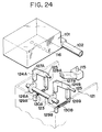
- Fig. 24 is a partially perspective view schematically showing the principal structure of a sixth embodiment of the recording apparatus to which the present invention is applicable.
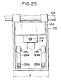
- Fig. 25 is a schematic plan view showing the supporting range of the carriage which is in its standby position in the recording apparatus shown in Fig. 24.
- Fig. 26 is a partially perspective view schematically showing the principal structure of a seventh embodiment of the recording apparatus to which the present invention is applicable.
- Fig. 27 is a schematic front view showing the state where the carriage enters its standby position in the recording apparatus shown in Fig. 26.
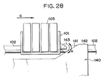
- Fig. 28 is a schematic front view showing the state where the carriage having a roller enters its standby position in the recording apparatus shown in Fig. 26.
- Fig. 29 is a schematic side view illustrating a mechanism for a gap adjustment between recording means and a recording medium in a recording apparatus.
- a plurality of given positions for fixing a carriage are defined by fixing means.
- the fixing means is so arranged that the carriage is fixed by utilizing the pressing force or the carriage is fixed by utilizing the tensioning force.
- the fixing means is provided with a buffering member as buffering means with respect to the load required to fix the carriage.
- the carriage is rotatively supported by a guide shaft.
- a rotation regulating means to regulate the rotation of the carriage, or to make the rotation regulating means a part of the recovery unit which constitutes a cap, or to arrange a coupling unit of the aforesaid fixing means for engaging with the carriage, which is located between the aforesaid guide shaft and rotation regulating means.
- the recording heads are capable of discharging a plurality of color ink materials for recording images in color on a recording medium.
- a cap is pressed to the recording heads to cover its discharging ports.
- the recording heads are arranged to utilize thermal energy for discharging ink and may be provided with the electrothermal transducers to generate the aforesaid thermal energy.
- a plurality (four in the present embodiment) of recording heads 15 are detachably mounted on a carriage 1.
- This carriage 1 is driven by a carriage motor 23 through a carriage belt 24 a part of which is connected to the carriage.
- the carriage can travel in the main scanning direction.
- the recording heads 15 can scan for recording.
- a recording medium (not shown) is fed by a feeding roller (not shown) driven by a sheet feeding motor 22 through gears 21 in the sub-scanning direction orthogonal to the aforesaid main scanning direction.
- This feeding roller is arranged below a platen roller 19. The recording medium being fed thereby is conveyed upward between a sheet pressing board 20 and the platen 19.
- the aforesaid recording medium is regulated by the sheet pressing board 20 and the platen 19, and a recording is made by ink discharged from the recording heads 15 to the recording area opposite to the recording heads 15. Then, the recording medium is exhausted to the upper part of the recording apparatus.
- a flexible substrate 25 transmits the printing data, driving power, and others to the recording heads 15.
- electrothermal transducers 26 are respectively arranged in the recording heads 15 for each of the liquid passages to generate the thermal energy to which an applied voltage is supplied. Then, when applying the driving signals, the electrothermal transducers 26 generate the thermal energy to enable the film boiling to be created for the formation of air bubbles in the respective ink liquid passages. By the development of these air bubbles, the ink droplets are discharged from the aforesaid discharging ports 27.
- a plurality of capping positions are defined as given fixing positions on one end side (the left-hand side in Fig. 1) of the scanning area of the carriage 1.
- the carriage 1 is shifted to the aforesaid capping positions, and then, the cap of a recovery unit (not shown, but to be described later) advances to abut upon the front end of the recording heads 15 under pressure and airtightly close the discharging ports (not shown). In this way, it is possible to prevent the discharging ports of the recording heads 15 from being dried as well as from any adhesion of dust particles or the like.
- the scanning area of the carriage 1 means that the maximum recordable width of a recording sheet inherent in a recording apparatus.
- Each of the above mentioned carriage 1, guide shaft 11, platen 19, and other components are housed in a chassis which serves as the main body of a recording apparatus which will be described later.
- the recording operation of this recording apparatus is executed under the control of a control unit 55 comprising an MPU 51 which controls the entire system of the apparatus while transmitting or receiving signals between each of the units of the recording apparatus; a ROM 52 storing the sequence or the like regarding the recording operation and processing; a RAM 53 used as the buffer for the recording data as well as the work area for the processing to be executed by the MPU 51, and others; and input and output ports 54.
- the control signals from the control unit 55 are supplied to a first, second, and third driving circuits 48, 49, and 50.
- the first, second, and third driving circuits 48, 49, and 50 drive the carriage motor 23, sheet feeding motor 22, and recording heads 15, respectively.
- control unit receives recording data from a computer serving as a host equipment through an interface circuit 46.
- the control operation of the recording apparatus is executed by operating the switches, keys, and the like which are provided for an operation panel 47.
- a position detection sensor serving as a position detection means which will be described later detects whether the carriage (not shown) is in the capping position (standby position) or not.
- FIG. 29 is a schematic side view showing the structure (of a gap adjusting mechanism) which uses a gap adjusting lever for the adjustment (control) of the above-mentioned distance to the recording sheet.
- a supporting shaft abutting member 117 which abuts upon a supporting shaft 103
- a gap adjusting lever 118 which engages with the supporting shaft abutting member 117 to be able to transmit the rotational force are rotatively supported in a carriage 101, respectively.
- a plurality of abutting surfaces in the example shown in Fig. 29, two locations
- the gap (distance to the recording sheet) g between the discharging port surface and the recording material 113 can be adjusted by the above-mentioned gap adjustment to a given correct value. Therefore, by operating the gap adjusting lever 118, the above-mentioned gap g can be adjusted to a correct value corresponding to the various thicknesses of the recording materials.
- Fig. 4 is a perspective view schematically showing the carriage and recovery unit which are characteristic parts of the present embodiment.
- Fig. 5 is a vertically sectional view schematically showing those elements shown in Fig. 4 observed in the direction indicated by an arrow A.
- a guide shaft 11 is installed to the chassis 60 and 61 of a recording apparatus.
- the four recording heads 15a, 15b, 15c, and 15d are provided to discharge the ink of different colors, cyanogen, magenta, yellow, and black, respectively.
- This carriage 1 is supported movably in the directions indicated by arrows A and B along the guide shaft 11, and also rotatively supported.
- the front part of the carriage 1 is supported by a shaft 33 on which it is mounted.
- the aforesaid four recording heads 15a, 15b, 15c, and 15d are arranged in a row in the traveling direction of the carriage 1 (in the direction B indicated by an arrow B and opposite direction thereto).
- a recovery unit 17 comprises the recovery unit main body 3 serving as its exterior part the front of which functions as a stopper 6 on the recovery unit side; a protective cap 9 having the four caps 14a, 14b, 14c, and 14d arranged at equal intervals to each other; a suction cap 7 made of a resilient material such as rubber to execute the recovery operation for the recording heads 15a, 15b, 15c, and 15d; and the lever 4, cam 2, and others which function as the fixing means which will be described later.
- the intervals between the four holes, the first, second, third, and fourth ones, are equal to each other. These intervals are also equal to those between the four caps 14a, 14b, 14c, and 14d as well as between the recording heads 15a, 15b, 15c, and 15d.
- the interval between the fourth hole 8d and the fifth hole 8e is equal to the one between the forth cap 14d and the suction cap 7.
- the central part of the lever 4 serving as fixing means is rotatively supported by a shaft 13 extensively installed in the recovery unit main body 13.
- a fixing pin 5 is integrally extruded having a flange 5a in mid way so that the pin can be inserted into the aforesaid five holes 8a, 8b, 8c, 8d, and 8e.
- an extrusion 4a is formed on the lower end of the other end thereof.
- the outer diameter of the fixing pin 5 is slightly smaller than that of the five holes 8a, 8b, 8c, 8d, and 8e, while the outer diameter of the foregoing flange 5a is slightly larger than the diameter of the holes 8a, 8b, 8c, 8d, and 8e.
- the stopper 10 on the carriage side and stopper 6 on the recovery unit side constitute rotation regulating means.
- a coil spring 12 is hocked to give a tensioning bias to the lever 4.
- a cam 2 having an extrusion 2a is integrally arranged on the rotational shaft 16 which is rotatively installed on the recovery unit main body 13. This cam is provided in order to drive the lever 4.
- This rotational shaft 16 is rotated only to a given angle by a cam driving motor 45 (refer to Fig. 6) through a transmission mechanism (not shown) comprising gears and others.
- the two shafts 13 and 16 are supported by the recovery unit main body 3.
- the guide shaft 11 is supported by the chassis 60 and 61. Therefore, the vibrations of the traveling carriage 1 are not transmitted to the cam 2 and lever 4.
- the first to fourth specific fixing positions are the position of the carriage 1 when the first to fourth recording heads 15a to 15d face the suction cap 7, respectively, while the fifth specific position is the position of the carriage 1 when the first to fourth recording heads 15a to 15d face the first to fourth caps 14a to 14d of the protective cap 9, respectively.
- These first to fifth specific fixing positions are registered in advance in the control unit 44 shown in Fig. 6.
- the position detection sensor 43 serving as position detection means is to detect the positions of the carriage 1 in the scanning direction.
- the control unit 44 controls the cam driving motor 45 to drive the rotational shaft 16 (refer to Fig. 5) to rotate in the direction indicated by an arrow C in Fig. 5.
- the extrusion 4a of the lever 4 disengages from the extrusion 2a of the cam 2 in the initial state.
- the one end of the lever 4 on the fixing pin 5 side is in the descending position.
- the carriage 1 is shifted in the direction indicated by the arrow B, that is, to the recovery unit 17 side.
- the cam driving motor 45 which is controlled by the control unit 44, the cam 2 incorporated in the recovery unit main body 3 rotates in the direction indicated by an arrow C.
- the extrusion 2a of the cam 2 disengages from the extrusion 4a of the lever 4. Consequently, due to the tension exerted by the coil spring 12, the lever 4 rotates in the direction indicated by an arrow E to press the fixing pin 5 upward.
- the fixing pin 5 thus pressed upward is inserted into the first hole 8a formed on the lower end of the carriage 1.
- the flange 5a of the fixing pin 5 abuts upon the carriage 1 under pressure to enable the carriage 1 to be fixed in the longitudinal direction of the guide shaft 11, and at the same time, the fixing pin 5 presses the carriage 1 upwardly to enable the carriage to rotate in the clockwise direction around the guide shaft 11 as shown in Fig. 5.
- the cam 2 rotates in the direction opposite to the direction indicated by the arrow C, so that the part of the lever on the cam 2 side is pressed upward to cause the fixing pin 5 to retract from the first hole 8a.
- the carriage 1 descends to the initial position to be supported by the shaft 33.
- the empty suction is executed to suck the ink in the suction cap 7 together with the air, and then, the suction cap 7 descends to leave the first recording head 15a at the same time.
- the recovery operations for the third and fourth recording heads 15c and 15d are further executed in the same manner as the foregoing series of operation. This time, the third and fourth holes 8c and 8d are utilized, respectively. Then, the recovery operations for the recording heads 15a to 15d are completed in this way.
- the carriage 1 In order to conduct the operation of the protective cap when the recording apparatus is not in use, the carriage 1 is at first shifted in the direction indicated by an arrow B to the fifth fixing position as given (protective capping position) where the first to fourth recording heads 15a to 15d face the first to fourth caps 14a to 14d of the protective cap 9.
- the cam 2 incorporated in the recovery unit main body 3 rotates in the direction indicated by the arrow C.
- the extrusion 2a of the cam 2 is caused to disengage from the extrusion 4a of the lever 4.
- the lever 4 rotates in the direction indicated by the arrow C to press the fixing pin 5 upward.
- the upwardly pressed fixing pin 5 is inserted into the fifth hole 8e formed on the lower end of the carriage 1.
- the carriage 1 is fixed in the longitudinal direction of the guide shaft 11, and at the same time, the fixing pin 5 presses the carriage 1 upwardly and causes the carriage 1 to rotate around the guide shaft 11.
- This motion to press the carriage 1 for its rotation is regulated by the stopper 10 on the carriage side provided for the carriage 1 and the stopper 6 on the recovery unit side provided for the recovery unit main body 3 side which abut upon each other.
- the protective cap 7 is raised by a driving means which is not shown after the carriage 1 has been fixed. Then, the first to fourth cap 14a to 15d are closely in contact with the first to fourth recording heads 15a to 15d, respectively; hence covering the respective discharging ports to complete the head protective capping.
- Fig. 7 is a vertically sectional view schematically showing a variation of the carriage fixing part according to the first embodiment.
- a hole is formed on one end of the lever 29 on the suction cap (not shown) side.
- a fixing pin 28 having a flange 28c is provided with a small-diameter shaft 28a, and this shaft 28a passes through the aforesaid hole of the lever 29. Then, a screw 28b is threaded over the lower end of the shaft 28a. Between the fixing pin 28 and lever 29, a coil spring 30 is provided so that the fixing pin 28 is biased upwardly.
- This coil spring 30 serves as a buffering member to buffer the impact exerted when the fixing pin 28 is inserted into the hole 8a of the carriage 1 so that the carriage 1 is raised to bring the stopper (not shown) on the recovery unit side and the stopper (not shown) on the carriage side to abut upon each other.
- Fig. 8 is a vertically sectional view schematically showing the carriage, recovery unit, and others which are the characteristic parts of a second embodiment of the recording apparatus according to the present invention.
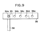
- Fig. 9 is a schematic view showing the carriage fixing unit shown in Fig. 8 observed in the direction indicated by an arrow F.
- a lever 56 is bent almost at 90° and formed in an L-letter shape when observed from its side.
- the structure is so arranged that the lever 56 pulls a carriage 31 in the right-hand direction in Fig. 8 and fixes it.
- the extrusion 36 made of a plate in an L-letter shape is integrally formed with the rear part of the carriage 31 as shown in Fig. 8 and Fig. 9.
- the first to fifth holes 34a to 34e are formed in the same manner as the first to fifth holes 8a to 8e (refer to Fig. 4) of the first embodiment.
- the other structures are the same as the first embodiment.
- the carriage 31 is shifted to the recovery unit 17 side in order to execute the first recovery operation for the first recording head 32a.
- the cam 2 incorporated in the recovery unit main body 3 rotates in the direction indicated by an arrow C.
- the extrusion 2a of the cam 2 is caused to disengage from the extrusion 56a of the lever 56.
- the lever 56 rotates in the direction indicated by an arrow E.
- a fixing pin 35 is inserted into the first hole 34a formed on the lower end of the carriage 31.
- the usual suction recovery operation
- the cam 2 rotates in the direction opposite to the direction indicated by the arrow C.
- the lever 56 on the cam 2 side is pressed upward to cause the fixing pin 35 to retract from the first hole 34a.
- the carriage 31 descends to the initial position.
- the empty suction of the suction cap 7 is executed, and then, the suction cap 7 descends to leave the first recording head 32a.
- the carriage 31 is shifted along the guide shaft 11 to the second fixing position as given where the second recording head-faces the suction cap 7.
- the cam 2 rotates in the direction indicated by the arrow C so that the fixing pin 35 is shifted to the right-hand side in Fig. 8 to be inserted into the second hole 34b (refer to Fig. 9) of the carriage 31.
- the carriage 31 is fixed in the longitudinal direction of the guide shaft 11 and the rotation of the carriage 31 is regulated.
- the usual suction recovery operation
- the empty suction of the suction cap 7 is conducted.
- the recovery operations for the third and fourth recording heads (not shown) are executed.
- the recovery operation is executed by the same series of the operations as described above, but the third and fourth holes 34c and 34d are used, respectively, this time. In this way, the recovery operations for the four recording heads are completed.
- the carriage 31 is at first shifted along the guide shaft 11 to the fifth fixing position as given (protective capping position) where the first to fourth recording heads face the first to fourth caps of the protective cap, respectively.
- the cam 2 incorporated in the recovery unit main body 3 rotates in the direction indicated by the arrow C.
- the extrusion 2a of the cam 2 is caused to disengage from the extrusion 33a of the lever 56.
- the lever 56 rotates in the direction indicated by the arrow E.
- the fixing pin 35 is shifted in the right-hand side in Fig. 8 to be inserted into the fifth hole 34e formed on the lower end of the carriage 31.
- the carriage 31 is fixed in the longitudinal direction of the guide shaft 11, and at the same time, the carriage 31 is pulled to the right-hand side in Fig. 8 to rotate around the guide shaft 11.
- This motion to rotate the carriage 31 is regulated by the stopper 10 on the carriage side provided for the carriage 1 and the stopper 6 on the recovery unit side provided for the recovery unit main body 3 which abut upon each other.
- the carriage 31 is fixed, and then, when the protective cap (not shown) is raised by means of the driving means which is not shown, the first to fourth caps of the protective cap contact the first to fourth recording heads airtightly, thus completing the protective capping for the heads.
- the second embodiment differs from the first embodiment in that the holes are arranged for the extrusion 36 which is the plate overhanging to the rear part of the carriage 31, while the lever 56 is bent almost at 90°.
- the second embodiment it is possible to fix the carriage effectively in a case where there is not much space on the lower end of the carriage but on the rear part thereof. Also, it may be possible to apply the variation shown in Fig. 7 to the second embodiment.
- Fig. 10 is a vertically sectional view schematically showing the carriage and recovery unit which are the characteristic parts of a third embodiment of the recording apparatus according to the present invention.
- Fig. 11 is a schematic view showing the carriage fixing unit shown in Fig. 10 observed in the direction indicated by an arrow G.
- an electromagnetic plunger 38 is provided as fixing means on the rear part of the mounting position of a carriage 39a for a recording head 37a.
- a fixing pin 41 having a flange 41a is fixed.
- the electromagnetic plunger 38 is connected to an excitation means which is not shown through a lead line 40.
- a control unit (not shown) controls whether the electromagnetic plunger 38 is excited or demagnetized.
- a plate 42 which is fixed to the recovery unit main body 3.
- the first to fifth holes 40a to 40e (refer to Fig. 11) are formed similarly to the first to fifth holes 8a to 8e in the first embodiment. All the other constructions are the same as those of the first embodiment.
- the carriage 39 is shifted to the recovery unit 17 side.
- the control means controls the aforesaid excitation means to cause the electromagnetic plunger 38 to be excited.
- Its output shaft 38a then descends together with the fixing pin 41.
- the descending fixing pin 41 is inserted into the first hole 40a of the plate 42.
- the fixing pin 41a abuts upon the upper end of the plate 42 under pressure. Hence, the carriage 39 is fixed in the longitudinal direction of the guide shaft 11.
- the fixing pin 41 functions to press the carriage 39 in the upward direction so that the leading end of the carriage 39 (in the left-hand side in Fig. 10) is raised around the guide shaft 11.
- This motion to raise the carriage is regulated by the stopper 10 on the carriage side provided for the carriage 39 and the stopper 6 on the recovery unit side provided for the recovery unit main body 3 which abut upon each other.
- the carriage 39 is fixed. Then, the recovery operation for the first recording head 37a is executed by the suction cap 7.
- the electromagnetic plunger 38 is demagnetized by the aforesaid excitation means.
- the fixing pin 41 is then raised to retract from the first hole 40a of the plate 42 so that the carriage 1 returns to the state before the execution of the above-mentioned series of operations.
- the empty suction of the suction cap 7 is executed. Then, the suction cap 7 descends to leave the first recording head 37a.
- the same series of operations are executed for the remaining second to fifth holes 40b to 40e, hence completing the recovery operations and the protective capping.
- the third embodiment is essentially different from the first and second embodiments in that the fixing pin and its driving systems are arranged on the carriage side (using an electromagnetic plunger as means to generate its driving force), while the holes are formed on the recovery unit side.
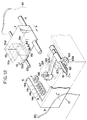
- Fig. 12 is a view illustrating a fourth embodiment of the recording apparatus according to the present invention, which is the same figure as Fig. 4.
- Fig. 13 is a detailed view illustrating the driving unit of the fixing pin shown in Fig. 12. In this respect, Fig. 13 represents a state that the fixing pin engages with a hole formed on the carriage.
- the lever 63 formed in an L-letter shape when observed from the side is rotatively supported by a shaft 62 the both ends of which are fixed in the recovery unit main body 3.
- extrusions 63a and 63b are formed, respectively.
- a fixing pin 66 is integrally formed at the leading end of the longer side 71b of the lever 63.
- a supporting member 70 which is biased by a coil spring 69 upwardly. This supporting member 70 is supported by the lever 63 through the coil spring 69, and also, arranged to pass through a hole 68 of an extruded piece formed on the recovery unit main body 3. The supporting member is guided by this hole 68 to move vertically.
- first and second cams 64 and 65 are arranged together. These first and second cams 64 and 65 are also provided with a recess 64a and an extrusion 65b, respectively.
- the first cam 64 presses the extrusion 63a formed on the longer side 71b of the lever 63 upwardly to enable the lever 63 to rotate in the direction indicated by an arrow C (the state represented by Fig. 13).
- the second cam 65 presses the extrusion 63b formed on the shorter side 71a of the lever 63 upwardly to enable the lever 63 to rotate oppositely in the direction indicated by the arrow C. All the other structures are the same as those of the first embodiment.
- the extrusion 63b of the shorter side 71a of the lever 63 is pressed upward by the extrusion 65b of the second cam 65 in the initial state. Meanwhile, the extrusion 63a of the longer side 71b of the lever 63 abuts on the recess 64a of the first cam 64. Thus, the longer side 71b of the lever 63 is in the descending position.
- the carriage 1 is shifted to the recovery unit 17 side, that is, in the direction indicated by an arrow B.
- first and second cams 64 and 65 rotate oppositely to the direction indicated by the arrow C by a cam driving motor (not shown) which is controlled by a control unit (not shown).
- the extrusion 65b of the second cam 65 disengages from the extrusion 63b of the lever 63.
- the recess 64a of the first cam 64 also disengages from the extrusion 63a of the lever 63. Consequently, the longer side 71b of the lever 63 is pressed upward by the first cam 64. Also, the fixing pin 66 is pressed upward.
- the upwardly pressed fixing pin 66 is inserted into the first hole 8a formed on the lower end of the carriage 1, and then, the supporting member 70 abuts upon the carriage 1 under pressure exerted by the resiliency of the coil spring 69, hence enabling the carriage 1 to rotate around the guide shaft 11.
- This motion to raise the carriage 1 for its rotation is regulated when the stopper 10 on the carriage side provided for the carriage 1 abuts upon the stopper 6 on the recovery unit side provided for the recovery unit main body 3.
- the carriage 1 is fixed.
- the suction cap 7 is raised by a driving means which is not shown to allow it contact the first recording head 15a airtightly for covering its discharge ports.
- the usual suction is executed to suck the ink in the first recording head 15a by means of the suction cap 7.
- the first and second cams 64 and 65 rotate in the direction indicated by the arrow C.
- the extrusion 63a of the longer side 71b of the lever 63 abuts upon the recess 64a of the first cam 64
- the extrusion 63b of the shorter side 71a of the lever 63 abuts upon the extrusion 65b of the second cam 65 and it is raised.
- the lever rotates reversely in the direction indicated by the arrow C and enables the fixing pin 66 to retract from the first hole 8a.
- the carriage 1 descends to the initial position to be supported by the shaft 33.
- the empty suction is executed to suck the ink in the suction cap 7 together with the air.
- the suction cap 7 descends to leave the first recording head 15a.
- the carriage 1 When the carriage 1 descends to the initial position, the carriage 1 is shifted in the direction indicated by the arrow B and suspended at the second fixing position as given where the second recording head 15b faces the suction cap 7 in order to execute the recovery operation for the second recording head 15b. Then, as in the foregoing series of operations, the first and second cams 64 and 65 rotate reversely in the direction indicated by the arrow C. The fixing pin 66 is pressed upward. The fixing pin 66 thus pressed is inserted into the second hole 8b of the carriage 1 this time to allow the carriage 1 to be fixed in the longitudinal direction of the guide shaft 11 and regulate the rotation of the carriage 1. In this state, the usual suction (recovery operation) is executed for the second recording head 15b.
- the empty suction is executed. Further, the recovery operations for the third and fourth recording heads 15c and 15d are executed in the same manner as the foregoing series of operations, but this time the third and fourth holes 8c and 8d are used, respectively. In this way, the recovery operations for the four recording heads 15a to 15d are completed.
- the carriage 1 When the protective capping operation is executed while the recording apparatus is out of use, the carriage 1 is at first shifted in the direction indicated by the arrow B to the position where the first to fourth caps of the protective cap 9 face the first to fourth recording heads 15a to 15d, respectively.
- the first and second cams 64 and 65 incorporated in the recovery unit main body 3 rotate reversely in the direction indicated by the arrow C to press the fixing pin 66 upward.
- the fixing pin 66 thus raised is inserted into the fifth hole 8e formed on the lower end of the carriage 1.
- the carriage 1 is fixed in the longitudinal direction of the guide shaft 11.
- the fixing pin 66 presses the carriage 1 upward to allow the carriage 1 to rotate around the guide shaft 11.
- This motion to raise the carriage 1 for its rotation is regulated when the stopper 10 on the carriage side provided for the carriage 1 abuts upon the stopper 6 on the recovery unit side provided at the fifth fixing position as given (protective capping position) where the recovery unit main body 3 faces the caps 14a to 14d.
- the carriage 1 is fixed, and then, the protective cap 7 is raised by a driving means which is not shown.
- the first to fourth caps 14a to 14d contact the first to fourth recording heads 15a to 15d to cover the respective discharging ports airtightly and complete the protective capping for the heads.
- the lever is almost in an L-letter shape.
- Fig. 14 is a bottom view schematically showing a variation of the recording apparatus according to the present invention.
- Fig. 15 is a schematic view showing the carriage fixing unit of this variation.
- Figs. 16A and 16B are views schematically showing the state of this variation at the time of the usual suction.
- Fig. 16A is a cross-sectional view schematically showing the carriage fixing unit by means of a fixing pin.
- Fig. 16B is a schematic view showing the suction cap and recording heads.
- Figs. 17A and 17B are views schematically showing the state of this variation at the time of the empty suction.
- Fig. 17A is a cross-sectional view schematically showing the carriage fixing unit by means of a fixing pin.
- Fig. 17B is a schematic view showing the suction cap and recording heads.
- the four recording heads, the first, second, fourth, and fifth heads 72a to 72d which can discharge ink of cyanogen, magenta, yellow, and black, respectively, are arranged on the carriage 1 in a row at intervals L (12.7 mm each).
- Each of the length M and width N of these first, second, third, and fourth holes 73a to 73d is 2.71 mm and 2.5 mm, respectively.
- the fifth hole 73e which is used at the time of protective capping is formed in a position apart from the fourth hole 73d by a distance S (10 mm).
- the length M and width O of this hole are 1.7 mm, respectively.
- the present embodiment is characterized in that the shape of the first, second, third, fourth, and fifth holes 73a to 73e is rectangular, and that the diameter K of the fixing pin is 1.65 mm as shown in Fig. 16A and is sufficiently smaller than the width N (2.5 mm) of each of the first, second, third, and fourth holes 73a to 73d.
- the usual suction of the recording heads 72a to 72d is executed by the suction cap 7 as shown in Fig.
- the fixing pin 76 is inserted into the first hole 73a of the carriage 1 which is located in the left side end in Fig. 16A.
- the carriage 1 is fixed in its scanning direction.
- the suction cap 7 contacts the recording head 72a airtightly, and the usual suction is executed to suck the ink by the suction cap 7 from the first recording head 72a as shown in Fig. 16B.
- the distance P between the fixing pin 76 and guide shaft 75 is 42.9 mm.
- the fixing pin 76 still remain in the first hole 73a according to the present embodiment as shown in Fig.
- fixing means is arranged between a carriage and recovery unit, but the arrangement is not necessarily limited thereto. There is no problem functionally even if the fixing means is arranged between the recording heads themselves and the recovery unit, and the other member.
- the present invention is applicable not only to an ink jet recording apparatus, but to the recording apparatus of a wire dot type or laser beam type. Also, the present invention is applicable to a recording apparatus in which its carriage is supported by the guide shaft but not rotatively. Further, the given fixing positions of the carriage are not necessarily limited to the capping position. These positions may be arranged at a standby position.
- Fig. 18 is a partially perspective view schematically showing the principle structure of a fifth embodiment of the recording apparatus to which the present invention is applicable.
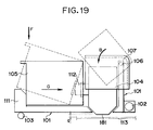
- Fig. 19 is a schematic side view showing a state of an ink tank attached to or detached from the recording apparatus shown in Fig. 18 observed in the direction indicated by an arrow A.
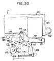
- Fig. 20 is a schematic side view showing the structures of the carriage fixing means and supporting means in the recording apparatus shown in Fig. 18 observed in the direction indicated by an arrow A.
- the same or equivalent members are referenced by the same reference marks.
- the description will be made of the case where an ink jet recording apparatus is exemplified as the recording apparatus.
- a carriage 101 is supported by a guide rail 102 and a supporting shaft 103 fixed to the apparatus main body so that the carriage is guided to reciprocate.
- recording means (recording head) 104 and an ink tank (ink cartridge) 105 mounted attachable to or detachable from the carriage 101.
- recording heads 104 and four ink tanks 105 each corresponding to each of the recording heads 104 are mounted.
- each of the recording heads 104 and ink tanks 105 are arranged to record in each different color of ink such as black, cyanogen, magenta, and yellow.
- the carriage 101 is supported and guided to reciprocate along the guide rail 102, and at the same time, its rotation around the guide rail 102 is regulated by the supporting shaft 103.
- the carriage 101 is coupled to a transmission belt or the like which is not shown, for example, and is able to reciprocate by means of this belt which is driven by a motor (not shown).
- a head cover 107 is mounted rotatively (open and closed) around the boss 106.
- This head cover 107 serves to position and hold the recording heads 104 in a given position on the carriage 101.
- each of the recording heads 104 are fixed on the carriage 101 in a state that each of them is properly positioned by rotating the head cover 107 in the direction indicated by an arrow B so that the cover is closed and set at its closed position.
- the head cover 107 is hocked (fixed) to the carriage 101 in the aforesaid closed position.
- the recording heads 104 and the ink tanks 105 can be set in a state that these can be removed easily.
- the structure is so arranged that handling the head cover 107 enables the recording heads 104 to be easily attached to or detached from the carriage 101.
- the ink tanks 105 can be easily positioned on the carriage 101 when pressed in the direction indicated by an arrow F with respect to the carriage 101 in a state that the tanks are sandwiched between an ink tank pressing unit 111 and the joint 112 of the recording heads 104 by the application of the supporting force exerted in the direction indicated by an arrow G by the ink tank pressing unit 111 of the carriage 101.
- the ink flow passages are formed between the ink tanks 105 and recording heads 104 airtightly, and ink is supplied from the corresponding ink tanks 105 to the recording heads 104, respectively.
- the ink tanks 105 can be easily detached from the carriage 101 by raising the tanks in the direction reverse to that indicated by the arrow F.
- the carriage 101 is supported to be able to reciprocate along the guide rail 102 in the direction indicated by an arrow K and also guided and supported rotatively around the guide rail 102.
- the guide rail 102 is supported by the recording apparatus main body.
- the recording heads 104 is mounted in the carriage 101 in a downward posture.
- a given space (gap) g is provided between the front end (discharging port surface) of the recording heads 104 and a recording material 113 (Fig. 19) such as a recording sheet.
- a recovery unit 121 for maintaining and recovering the discharging capability of the discharging ports 182 is arranged at the standby position of the carriage 101 or in its vicinity which is out of the recording area of the recording apparatus.
- This recovery unit 121 is provided with a cap 114 to airtightly cover (capping) the discharging port surface 181 in order to prevent the ink in the discharging ports 182 from being dried as well as the dust particles from adhering to the discharging port surface 181, a suction pump (not shown) to suck the ink from the discharging ports 182 by generating a negative pressure in the cap 114 in a capping state, and others. Then, the arrangement is made so that the recovery operation is executed for the recording heads 104 in the standby position.
- the cap 114 is installed on a cap holder 131.
- a fixing pin 115 is provided, which enables the carriage 101 to be positioned in the standby position.
- a transmission shaft 123 which is driven to rotate by the driving force from the recovery unit 121.
- the fixing pin 115 is vertically movable by means of a fixed pin cam 122 provided for the transmission shaft 123. Then, when the carriage 101 travels to the standby position, the fixing pin 115 fits in a hole 116 formed on the reverse side of the carriage 101 (as the holes 8a to 8d in the above-mentioned first to fourth embodiments, for example). Then, the structure is made to set the carriage 101 in a given position by pressing the pin further upward.
- a carriage supporting lever 124 is provided to constitute supporting means according to the present invention.
- This supporting lever (supporting member) 124 is rotatively supported around a shaft 125, and arranged to be rotationally driven by means of the supporting lever cam 126 provided for the aforesaid transmission shaft 123.
- a carriage supporting unit 127 is formed.
- this carriage supporting unit 127 is moved in the vertical direction.
- a compression spring 130 is installed between the arm portion on the other end of the supporting lever 124 and a hock 129 on the apparatus main body side. By this compression spring 130, the supporting lever 124 is biased in the direction in which the carriage supporting unit 127 retracts from the reverse side of the carriage 101 (downward direction).
- the cam extrusion 132 of the supporting lever cam 126 presses the cam abutting part 133 of the carriage supporting lever 124 upward, thus raising the carriage supporting lever 124 around the shaft 125.
- the supporting lever cam 126 is suspended in a state that the carriage supporting unit 127 of the carriage supporting lever 124 has ascended most, that is, the state where the carriage supporting unit 127 abuts upon the bottom end of the carriage 101.
- the fixing pin 115 presses the carriage 101 upward, and at the same time, the cap 114 abuts upon the discharging port surface 181 under pressure for capping.
- This state then constitutes the standby state of the recording apparatus (carriage 101) according to the present embodiment.
- the attaching or detaching operation of the ink tanks 105, the gap adjustment operation for the recording heads 104 (the gap adjustment by means of the lever 118 shown in Fig. 29, for example), or other operations to be done on the carriage 101 will be executed.
- the supporting lever cam 126 is rotated reversely in the direction indicated by an arrow L to bring the cam extrusion 132 not to abut upon the cam abutting part 133. Then, the springing force of the compression spring 130, the carriage supporting lever 124 rotates around the shaft 125 to enable the carriage supporting unit 127 to retract from the carriage 101. At the same time, the fixing pin 115 descends to the position where it is not in contact with the carriage 101. The recording heads 101 on the carriage 101 also leave the cap 114, hence releasing the standby state of the carriage 101 to make the recording operation ready.
- the fixing pin 115 and the carriage supporting lever 124 are in a state (retracted state) in which these are not extruded in the traveling space (traveling path) of the carriage 101. Therefore, with the above-mentioned structures, the carriage 101 can be positioned exactly and held reliably in the standby position without any load added anew to the traveling carriage 101 in the scanning direction for the recording operation and others.
- Fig. 21 is a plan view schematically showing the fixing and supporting state of the carriage 101 in the standby state with the structures arranged as shown in Fig. 18 to Fig. 20.
- a reference numeral 134 designates the supporting area where the fixing pin 115 abuts upon the carriage 101, while 135, the supporting area where the carriage supporting lever 124 abuts upon the carriage 101.
- the fixing pin 115 should be provided with a function to position and fix the carriage 101 in the standby position, it is preferable to select the position where the fixing pin 115 and the positioning hole 116 of the carriage 101 are coupled in the vicinity of the discharging port surface 118 or in the vicinity of the guide rail 102.
- the supporting area 134 shown in Fig. 21 is selected as a position to satisfy these conditions.
- the supporting area 135 in Fig. 21 is selected as a position to satisfy these conditions. It is particularly effective to select the supporting positions for the carriage supporting lever 124 in the locations such as these when a carriage 101 is elongated in the horizontal direction (that is, the dimension M in Fig. 21 is set long).
- the structure is so arranged that when the carriage 101 arrives at the standby position, the fixing pin 115 and the supporting member (carriage supporting lever) 124 can support the entire body of the carriage 101.
- the fixing pin 115 and the supporting member (carriage supporting lever) 124 can support the entire body of the carriage 101.
- the structure is so arranged that when the carriage 101 is out of the standby position, the fixing pin 115 and carriage supporting lever 124 retract from the carriage traveling passage. It is thus possible to obtain the effect that no load is needed for the carriage 101 to travel in the scanning direction, to bring the carriage 101 to the standby position, and to position and hold it in the standby position.
- the compression spring 130 is adopted to exert the biasing force to bring the carriage supporting lever 124 to the storing position, but a tension spring 136 may be used instead of the compression spring 130 as shown in Fig. 22.
- a tension spring 136 may be used instead of the compression spring 130 as shown in Fig. 22.
- the other parts constituting the structure shown in Fig. 22 are the same as those in Fig. 18 and Fig. 20.
- the corresponding parts are designated by the same reference marks, and the description thereof will be omitted.
- Fig. 24 is a partially perspective view schematically showing the principle structure of a sixth embodiment of the recording apparatus to which the present invention is applicable.
- Fig. 25 is a plan view schematically showing the state where the carriage 101 is fixed and supported in the standby position in the structure shown in Fig. 24.
- the carriage 101 in the standby position is supported by two carriage supporting levers 124A and 124B.
- the present embodiment has essentially the same structure as the embodiment shown in Fig 18 to Fig. 21.
- the carriage 101 in the standby position is then fixed and supported in a total of three locations as shown in Fig. 25, that is, the supporting area 134 by the fixing pin 115, the supporting area 135A by the carriage supporting lever 124, and the supporting area 135B by the carriage supporting lever 124B.
- the fixing pin 115 positions and fixes the carriage 101 as in the case of the foregoing fifth embodiment.
- the two carriage supporting levers 124A and 124B support the carriage 101.
- the discharging port surface 181 of the recording heads 104 abuts upon the cap 114 under pressure for the capping of the discharging ports 182.
- the operations will be executed essentially in the same way as the fifth embodiment.
- the same functional effects as in the fifth embodiment can be obtained by the present embodiment.
- the carriage 101 being supported by the fixing pin 115 and two other points, it is more advantageous than the fifth embodiment in terms of the prevention of the carriage 101 from being bent or deformed when the force acts on the carriage 101 by the execution of the attachment or detachment of the recording heads 104 and ink tanks 105, the gap adjustment for the recording heads 104, or others.
- the carriage 101 is particularly effective to support the carriage 101 in two locations by use of the two supporting levers 124A and 124B as in the present embodiment if there is a need for pressing the location near the gravity of the carriage upward by the fixing pin 115 because the carriage 101 weighs greatly, or the carriage 101 should be supported by the fixing pin 115 in the vicinity of its center as shown in Fig. 25 because the position of the aforesaid positioning hole 116 is restricted due to the unavailability of space on the carriage 101, or further, the carriage 101 is an elongated shape in both directions of the guide rail (the shape which has a great dimension at N in Fig. 25).
- the supporting lever cams 126A and 126B and compression springs 130A and 130B are provided individually corresponding to the two carriage supporting lever 124A and 124B, respectively, but it may be possible to arrange a structure so that the two points of the carriage 101 can be supported simultaneously by one carriage supporting lever (one supporting lever cam and one compression spring) by modifying the configuration of the carriage supporting lever in place of those individually arranged ones.
- the description has been made of a case where the carriage 101 is supported at two points (at 135A and 135B) it may be possible to arrange a structure so that the carriage 101 can be supported at plural points, three or more, at the same time. It is still possible to obtain by the application of such modifications as these the same functional effects as each of the foregoing embodiments.
- Fig. 26 is a partially perspective view schematically showing the principle structure of a seventh embodiment of the recording apparatus to which the present invention is applicable.
- Fig. 27 is a schematically partial front view showing the operation of the carriage 101 and the standby state of the carriage 101 shown in Fig. 26 observed in the direction indicated by an arrow P.
- the carriage 101 which has arrived at the standby position is supported by a carriage supporting slant face 140 provided on the apparatus main body side.
- the present embodiment has essentially the same structure as the fifth embodiment shown in Fig. 18 to Fig. 21.
- the foregoing carriage supporting slant face 140 constitutes a fixed carriage supporting means, and in the present embodiment, this face is formed by utilizing the outer wall portion of the recovery unit 121.
- the carriage supporting slant face 140 is of a shape having the slant face portion 141 inclined in the traveling direction of the carriage 101, and a vertex 142 which supports the carriage 101 in the standby position.
- the carriage 101 travels in the direction indicated by an arrow Q in order to enter the standby state.
- the right lower end of the carriage 101 (in Fig. 26) abuts upon the slant face portion 141 of the carriage 101 supporting slant face 140.
- the carriage 101 is being pressed upward along the slant portion 141 while being shifted toward the aforesaid vertex 142.
- the carriage is suspended at the standby position in a state of being supported by the aforesaid vertex 142 in a position indicated by the solid line in Fig. 27.
- the fixing pin 115 is pressed upward by the rotation of the fixing pin cam 122.
- the fixing pin 115 fits in the carriage positioning hole 116 (Fig. 20) of the carriage 101, thus enabling the carriage 101 to be positioned and fixed in the standby position.
- the vertex 142 of the carriage supporting slant face 140 abuts upon the bottom end of the carriage 101 or in the position extremely close to it.
- the carriage 101 is fixed and supported by the fixing pin 115 thus raised, and the vertex 142 of the carriage supporting slant face 140.
- the fixing pin 115 descends to the retracted position by the rotation of the fixing pin cam 122, and then, the carriage 101 travels in the direction opposite to that indicated by the arrow Q. In this case, the carriage 101 is slidably lowered on the slant face portion 141 of the carriage supporting slant face 140, thus entering the required recording operation.
- a load reducing means such as a rotative roller is provided in the part where the carriage 101 abuts upon the slant face portion 141.
- Fig. 28 is a schematically partial front view showing an arrangement of the provision of a rotative roller 143 for the carriage 101 in the structure shown in Fig. 26, and Fig. 27.
- Fig. 28 is a schematically partial front view showing an arrangement of the provision of a rotative roller 143 for the carriage 101 in the structure shown in Fig. 26, and Fig. 27.
- the rotational direction of the roller 143 is represented by an arrow R, but if only the roller 143 can rotate by the frictional force between the roller and the slant face portion 141, the rotational direction of the roller 143 is not necessarily limited to the one indicated by the arrow R.
- the carriage supporting slant face 140 is provided for the recovery unit 121 .
- the carriage supporting means 140 is constituted by a member which is fixedly provided on the apparatus main body side. Hence, there is no need for any complicated mechanism, and it is possible to obtain an effect that the carriage 101 can be supported only by utilizing the movement of the carriage 101 in the scanning direction.
- the present invention is equally applicable to a wire dot type, thermal sensitive type, thermal transfer type, laser beam type, or others if only the recording apparatus is the one having the mode that the recording heads and others are detachably mounted on the carriage, and it is possible to obtain the same effects.
- a color ink jet recording apparatus using plural (four) recording means (recording heads or head cartridges) for recording in different colors is exemplified and described, but irrespective of the number of recording means and the colors in which the recording is executed, the present invention is widely applicable to a recording apparatus using one recording means; to a recording apparatus for gradation recording using a plurality of recording means to record in one and the same color but in different densities; or to the like, and it is possible to obtain the same effects.
- an ink jet recording apparatus which is one of the recording apparatuses to which the present invention is applicable, uses recording means (recording heads) having electromechanical transducers such as piezoelectric elements, but the present invention is particularly effective in applying it to an ink jet recording apparatus adopting a method of discharging ink by utilizing thermal energy because with such a method it is possible to attain a highly densified recording in a high precision.
- the principle is such that at least one driving signal, which provides a rapid temperature rise beyond a departure from nucleation boiling point in response to recording information, is applied to an electrothermal transducer disposed on a liquid (ink) retaining sheet or liquid passage whereby to cause the electrothermal transducer to generate thermal energy to produce film boiling on the thermoactive portion of the recording means (recording head); thus effectively leading to the resultant formation of a bubble in the recording liquid (ink) one to one for each of the driving signals.
- the liquid (ink) is discharged through a discharging port to produce at least one droplet.
- the driving signal is preferably in the form of pulses because the development and contraction of the bubble can be effectuated instantaneously, and then, the liquid (ink) is discharged with an excellent response.
- the driving signal in the form of pulses is preferably such as disclosed in the specifications of U.S. Patent Nos. 4,463,359 and 4,345,262.
- the temperature increasing rate of the thermoactive surface is preferably such as disclosed in the specification of U.S. Patent No. 4,313,124 for an excellent recording in a better condition.
- the structure of the recording head may be as shown in each of the above-mentioned specifications wherein the structure is arranged to combine the discharging ports, liquid passages, and the electrothermal transducers as disclosed in the above-mentioned patents (linear type liquid passage or right angled liquid passage).
- the structure such as disclosed in the specifications of U.S. Patent Nos. 4,558,333 and 4,459,600, in which the thermoactive portions are arranged in a curved area, is also included in the present invention.
- the present invention is applicable to the structure disclosed in Japanese Laid-Open Application No.
- the recording can be executed reliably and efficiently irrespective of the mode of the recording head.
- the present invention is effectively applicable to a serial type recording head exemplified above; to the recording head which is fixed on the main assembly or a replaceable chip type recording head which is connected electrically with the main apparatus and for which the ink is supplied when it is mounted in the main assemble; or to a cartridge type recording head having an ink container integrally provided for the head itself.
- constituents of a recording head it is preferable to additionally provide recording head recovery means and preliminarily auxiliary means because these means will contribute to making the effectiveness of the present invention more stable.
- such constituents are capping means for the recording head, cleaning means, compression or suction means, preliminary heating means such as electrothermal transducers or heating elements other than such transducers or the combination of those types of elements, and the preliminary discharge mode besides the regular discharge for recording.
- the present invention is extremely effective in applying it to an apparatus having at least one of a multi-color mode with ink of different colors, a full-color mode using the mixture of the colors, or a mode using the kinds of ink which are of the same color but in different densities, irrespective of whether the recording head is integrally structured or it is structured by a combination of plural recording heads.
- the ink has been described as liquid, but it may be an ink material which is solidified below the room temperature but liquefied at the room temperature. Since the ink is controlled within the temperature not lower than 30°C and not higher than 70°C to stabilize its viscosity for the provision of the stable ejection in general, the ink may be such that it can be liquefied when the applicable recording signals are given.
- an ink having a nature of being liquefied only by the application of thermal energy such as an ink capable of being ejected as ink liquid by enabling itself to be liquefied anyway when the thermal energy is given in accordance with recording signals, such as an ink which will have already begun solidifying itself by the time it reaches a recording medium.
- the ink such as this, it may be possible to retain the ink as a liquid or solid material in through holes or recesses formed in a porous sheet as disclosed in Japanese Patent Laid-Open Application No. 54-56847 or Japanese Patent Laid-Open Application No. 60-71260 in order to execute a mode with which to enable the ink to face the electrothermal transducers in such a state.
- the most effective method for the respective kinds of ink mentioned above is the one which is capable of implementing the film boiling method as described above.
- a recording apparatus there are a copying apparatus combined with a reader or the like, and an apparatus executing a mode as a facsimile apparatus having the transmission and reception functions in addition to those which are used as an image output terminal of an information processing equipment such as a computer.
- the recovery operations of the recording heads can be executed with one suction pump and suction cap for plural times continuously and reliably.
- supporting means to be correlatively movable with respect to the apparatus main body, it is possible to make the supporting means retractable at any time other than the standby time for the carriage, thus obtaining an effect that the carriage can be supported while in its standby position without any extra loads which will otherwise be exerted on the traveling carriage.
- a recording apparatus having a carriage which scans along a guide shaft and which is provided with recording heads includes position detection means for detecting the positions of the carriage in the scanning direction; and fixing means for engaging with the carriage to regulate the carriage in the scanning direction when it is detected by the position detection means that the carriage is in a given fixing position and fixing the carriage in the given fixing position.
- this recording apparatus is capable of preventing the carriage from being bent or deformed when the ink tanks and recording heads are detachably mounted or the gap adjustment for the recording heads are executed on the carriage, thus enabling the operation and positioning of the carriage to be executed exactly.
Landscapes
- Ink Jet (AREA)
- Character Spaces And Line Spaces In Printers (AREA)
- Common Mechanisms (AREA)
Applications Claiming Priority (6)
| Application Number | Priority Date | Filing Date | Title |
|---|---|---|---|
| JP23377492 | 1992-09-01 | ||
| JP23377492 | 1992-09-01 | ||
| JP233774/92 | 1992-09-01 | ||
| JP32479592 | 1992-11-10 | ||
| JP324795/92 | 1992-11-10 | ||
| JP32479592 | 1992-11-10 |
Publications (3)
| Publication Number | Publication Date |
|---|---|
| EP0585888A2 true EP0585888A2 (fr) | 1994-03-09 |
| EP0585888A3 EP0585888A3 (en) | 1994-06-15 |
| EP0585888B1 EP0585888B1 (fr) | 1999-12-08 |
Family
ID=26531195
Family Applications (1)
| Application Number | Title | Priority Date | Filing Date |
|---|---|---|---|
| EP93113931A Expired - Lifetime EP0585888B1 (fr) | 1992-09-01 | 1993-08-31 | Dispositif de détection de la position et de verrouillage du chariot "pour un appareil d'enregistrement" |
Country Status (5)
| Country | Link |
|---|---|
| US (1) | US6010204A (fr) |
| EP (1) | EP0585888B1 (fr) |
| KR (1) | KR970003661B1 (fr) |
| AT (1) | ATE187393T1 (fr) |
| DE (1) | DE69327208T2 (fr) |
Cited By (3)
| Publication number | Priority date | Publication date | Assignee | Title |
|---|---|---|---|---|
| EP0775582A3 (fr) * | 1995-11-24 | 1998-01-28 | Samsung Electronics Co., Ltd. | Détermination d'une position initiale d'une tête d'imprimante à jet d'encre et protection contre des erreurs de libération du capuchon |
| EP0844091A3 (fr) * | 1996-11-22 | 1999-04-14 | Canon Kabushiki Kaisha | Un appareil d'enregistrement à jet d'encre |
| CN106739560A (zh) * | 2016-11-30 | 2017-05-31 | 郑州新世纪数码科技股份有限公司 | 运行安全和精准的小车架 |
Families Citing this family (9)
| Publication number | Priority date | Publication date | Assignee | Title |
|---|---|---|---|---|
| JP2002337415A (ja) * | 2001-03-15 | 2002-11-27 | Canon Inc | キャリッジを備える装置 |
| JP4633965B2 (ja) * | 2001-05-24 | 2011-02-16 | エスアイアイ・プリンテック株式会社 | インクジェットヘッド及びインクジェット式記録装置 |
| US7068401B2 (en) * | 2002-05-31 | 2006-06-27 | Hewlett-Packard Development Company, L.P. | Optical scanning apparatus having a carriage locking device |
| JP4223310B2 (ja) * | 2003-03-27 | 2009-02-12 | 株式会社リコー | インクジェット記録装置および画像形成装置 |
| US7724276B2 (en) * | 2003-11-03 | 2010-05-25 | Hewlett-Packard Development Company, L.P. | Optical assembly lock/unlock apparatus and method |
| US7223033B2 (en) * | 2005-04-26 | 2007-05-29 | Xiaoxi Huang | Pinch control in a printer |
| JP5274115B2 (ja) * | 2008-06-12 | 2013-08-28 | キヤノン株式会社 | インクジェット記録装置及びその制御方法 |
| JP5471655B2 (ja) * | 2010-03-17 | 2014-04-16 | 株式会社リコー | 画像形成装置 |
| JP5786566B2 (ja) * | 2011-08-31 | 2015-09-30 | セイコーエプソン株式会社 | 液体噴射装置 |
Family Cites Families (18)
| Publication number | Priority date | Publication date | Assignee | Title |
|---|---|---|---|---|
| US4208139A (en) * | 1974-09-06 | 1980-06-17 | Sharp Kabushiki Kaisha | Carriage position control in a printer of the carriage traveling mode |
| JPS549928A (en) * | 1977-06-25 | 1979-01-25 | Konishiroku Photo Ind Co Ltd | Ink jet recorder |
| CA1127227A (fr) * | 1977-10-03 | 1982-07-06 | Ichiro Endo | Procede d'enregistrement a jet liquide et appareil d'enregistrement |
| JPS5936879B2 (ja) * | 1977-10-14 | 1984-09-06 | キヤノン株式会社 | 熱転写記録用媒体 |
| US4177471A (en) * | 1977-11-04 | 1979-12-04 | Silonics, Inc. | Carriage and raceway mechanism for an ink jet printer |
| US4330787A (en) * | 1978-10-31 | 1982-05-18 | Canon Kabushiki Kaisha | Liquid jet recording device |
| US4345262A (en) * | 1979-02-19 | 1982-08-17 | Canon Kabushiki Kaisha | Ink jet recording method |
| US4463359A (en) * | 1979-04-02 | 1984-07-31 | Canon Kabushiki Kaisha | Droplet generating method and apparatus thereof |
| US4313124A (en) * | 1979-05-18 | 1982-01-26 | Canon Kabushiki Kaisha | Liquid jet recording process and liquid jet recording head |
| US4558333A (en) * | 1981-07-09 | 1985-12-10 | Canon Kabushiki Kaisha | Liquid jet recording head |
| JPS59123670A (ja) * | 1982-12-28 | 1984-07-17 | Canon Inc | インクジエツトヘツド |
| JPS59138461A (ja) * | 1983-01-28 | 1984-08-08 | Canon Inc | 液体噴射記録装置 |
| JPS6071260A (ja) * | 1983-09-28 | 1985-04-23 | Erumu:Kk | 記録装置 |
| JP2522770B2 (ja) * | 1986-08-05 | 1996-08-07 | キヤノン株式会社 | インクジェット装置 |
| EP0442713B1 (fr) * | 1990-02-13 | 1995-05-17 | Canon Kabushiki Kaisha | Appareil d'enregistrement avec tête d'enregistrement à jet d'encre |
| CA2040120C (fr) * | 1990-04-11 | 1996-03-26 | Norifumi Koitabashi | Methode de recuperation d'encre injectee pour tete d'ecriture a jet d'encre et dispositif connexe |
| JP3169023B2 (ja) * | 1990-10-12 | 2001-05-21 | セイコーエプソン株式会社 | インクジェット記録装置 |
| EP0494693B1 (fr) * | 1991-01-11 | 1998-04-01 | Canon Kabushiki Kaisha | Appareil d'enregistrement par jet d'encre |
-
1993
- 1993-08-31 AT AT93113931T patent/ATE187393T1/de not_active IP Right Cessation
- 1993-08-31 KR KR1019930017102A patent/KR970003661B1/ko not_active Expired - Fee Related
- 1993-08-31 EP EP93113931A patent/EP0585888B1/fr not_active Expired - Lifetime
- 1993-08-31 DE DE69327208T patent/DE69327208T2/de not_active Expired - Fee Related
-
1996
- 1996-09-18 US US08/710,493 patent/US6010204A/en not_active Expired - Fee Related
Cited By (5)
| Publication number | Priority date | Publication date | Assignee | Title |
|---|---|---|---|---|
| EP0775582A3 (fr) * | 1995-11-24 | 1998-01-28 | Samsung Electronics Co., Ltd. | Détermination d'une position initiale d'une tête d'imprimante à jet d'encre et protection contre des erreurs de libération du capuchon |
| EP0844091A3 (fr) * | 1996-11-22 | 1999-04-14 | Canon Kabushiki Kaisha | Un appareil d'enregistrement à jet d'encre |
| US5992966A (en) * | 1996-11-22 | 1999-11-30 | Canon Kabushiki Kaisha | Ink jet recording apparatus |
| CN106739560A (zh) * | 2016-11-30 | 2017-05-31 | 郑州新世纪数码科技股份有限公司 | 运行安全和精准的小车架 |
| CN106739560B (zh) * | 2016-11-30 | 2018-05-04 | 郑州新世纪数码科技股份有限公司 | 运行安全和精准的小车架 |
Also Published As
| Publication number | Publication date |
|---|---|
| US6010204A (en) | 2000-01-04 |
| DE69327208D1 (de) | 2000-01-13 |
| KR940006787A (ko) | 1994-04-25 |
| DE69327208T2 (de) | 2000-06-15 |
| EP0585888A3 (en) | 1994-06-15 |
| EP0585888B1 (fr) | 1999-12-08 |
| KR970003661B1 (ko) | 1997-03-20 |
| ATE187393T1 (de) | 1999-12-15 |
Similar Documents
| Publication | Publication Date | Title |
|---|---|---|
| EP0442713B1 (fr) | Appareil d'enregistrement avec tête d'enregistrement à jet d'encre | |
| US6010204A (en) | Recording apparatus with structure for locking and supporting recording head carriage at home position | |
| US6729709B2 (en) | Ink-jet printing method and apparatus | |
| EP0442470B1 (fr) | Appareil d'enregistrement par jet d'encre | |
| JP3204815B2 (ja) | 記録装置 | |
| US6130682A (en) | Ink jet recording apparatus with detection of discharge malfunction | |
| JP3234087B2 (ja) | インクジェット記録装置 | |
| JPH0664160A (ja) | インクジェット記録装置 | |
| US6050673A (en) | Recording apparatus with control of carriage driving motor | |
| JPH0952374A (ja) | インクジェット式記録装置 | |
| EP0570988B1 (fr) | Système d'enregistrement par jet d'encre | |
| JPH04286655A (ja) | インクジェット記録装置 | |
| US6834938B2 (en) | Ink jet recording apparatus | |
| JP3376173B2 (ja) | インクジェット記録装置 | |
| JPH03234664A (ja) | インクジェット記録装置 | |
| JPH09187954A (ja) | インクジェット記録装置 | |
| JPH1044467A (ja) | インクジェット記録装置及びファクシミリ装置 | |
| JPH06126969A (ja) | インクジェット記録装置 | |
| JP2675909B2 (ja) | インクジェット記録装置 | |
| JP3332523B2 (ja) | 記録装置 | |
| JP3295158B2 (ja) | 記録装置 | |
| JPH06255114A (ja) | インクジェット記録装置 | |
| JPH06198998A (ja) | 記録装置 | |
| JPH03234640A (ja) | インクジェット記録装置 | |
| JPH0478540A (ja) | インクジェット記録装置 |
Legal Events
| Date | Code | Title | Description |
|---|---|---|---|
| PUAI | Public reference made under article 153(3) epc to a published international application that has entered the european phase |
Free format text: ORIGINAL CODE: 0009012 |
|
| AK | Designated contracting states |
Kind code of ref document: A2 Designated state(s): AT BE CH DE DK ES FR GB GR IE IT LI LU NL PT SE |
|
| PUAL | Search report despatched |
Free format text: ORIGINAL CODE: 0009013 |
|
| AK | Designated contracting states |
Kind code of ref document: A3 Designated state(s): AT BE CH DE DK ES FR GB GR IE IT LI LU NL PT SE |
|
| 17P | Request for examination filed |
Effective date: 19941102 |
|
| 17Q | First examination report despatched |
Effective date: 19951215 |
|
| GRAG | Despatch of communication of intention to grant |
Free format text: ORIGINAL CODE: EPIDOS AGRA |
|
| GRAG | Despatch of communication of intention to grant |
Free format text: ORIGINAL CODE: EPIDOS AGRA |
|
| GRAG | Despatch of communication of intention to grant |
Free format text: ORIGINAL CODE: EPIDOS AGRA |
|
| GRAH | Despatch of communication of intention to grant a patent |
Free format text: ORIGINAL CODE: EPIDOS IGRA |
|
| GRAH | Despatch of communication of intention to grant a patent |
Free format text: ORIGINAL CODE: EPIDOS IGRA |
|
| GRAA | (expected) grant |
Free format text: ORIGINAL CODE: 0009210 |
|
| AK | Designated contracting states |
Kind code of ref document: B1 Designated state(s): AT BE CH DE DK ES FR GB GR IE IT LI LU NL PT SE |
|
| PG25 | Lapsed in a contracting state [announced via postgrant information from national office to epo] |
Ref country code: SE Free format text: THE PATENT HAS BEEN ANNULLED BY A DECISION OF A NATIONAL AUTHORITY Effective date: 19991208 Ref country code: NL Free format text: LAPSE BECAUSE OF FAILURE TO SUBMIT A TRANSLATION OF THE DESCRIPTION OR TO PAY THE FEE WITHIN THE PRESCRIBED TIME-LIMIT Effective date: 19991208 Ref country code: LI Free format text: LAPSE BECAUSE OF FAILURE TO SUBMIT A TRANSLATION OF THE DESCRIPTION OR TO PAY THE FEE WITHIN THE PRESCRIBED TIME-LIMIT Effective date: 19991208 Ref country code: GR Free format text: LAPSE BECAUSE OF NON-PAYMENT OF DUE FEES Effective date: 19991208 Ref country code: ES Free format text: THE PATENT HAS BEEN ANNULLED BY A DECISION OF A NATIONAL AUTHORITY Effective date: 19991208 Ref country code: CH Free format text: LAPSE BECAUSE OF FAILURE TO SUBMIT A TRANSLATION OF THE DESCRIPTION OR TO PAY THE FEE WITHIN THE PRESCRIBED TIME-LIMIT Effective date: 19991208 Ref country code: BE Free format text: LAPSE BECAUSE OF FAILURE TO SUBMIT A TRANSLATION OF THE DESCRIPTION OR TO PAY THE FEE WITHIN THE PRESCRIBED TIME-LIMIT Effective date: 19991208 Ref country code: AT Free format text: LAPSE BECAUSE OF FAILURE TO SUBMIT A TRANSLATION OF THE DESCRIPTION OR TO PAY THE FEE WITHIN THE PRESCRIBED TIME-LIMIT Effective date: 19991208 |
|
| REF | Corresponds to: |
Ref document number: 187393 Country of ref document: AT Date of ref document: 19991215 Kind code of ref document: T |
|
| REG | Reference to a national code |
Ref country code: CH Ref legal event code: EP |
|
| REF | Corresponds to: |
Ref document number: 69327208 Country of ref document: DE Date of ref document: 20000113 |
|
| REG | Reference to a national code |
Ref country code: IE Ref legal event code: FG4D |
|
| ET | Fr: translation filed | ||
| ITF | It: translation for a ep patent filed | ||
| PG25 | Lapsed in a contracting state [announced via postgrant information from national office to epo] |
Ref country code: DK Free format text: LAPSE BECAUSE OF FAILURE TO SUBMIT A TRANSLATION OF THE DESCRIPTION OR TO PAY THE FEE WITHIN THE PRESCRIBED TIME-LIMIT Effective date: 20000308 |
|
| PG25 | Lapsed in a contracting state [announced via postgrant information from national office to epo] |
Ref country code: PT Free format text: LAPSE BECAUSE OF FAILURE TO SUBMIT A TRANSLATION OF THE DESCRIPTION OR TO PAY THE FEE WITHIN THE PRESCRIBED TIME-LIMIT Effective date: 20000309 |
|
| NLV1 | Nl: lapsed or annulled due to failure to fulfill the requirements of art. 29p and 29m of the patents act | ||
| REG | Reference to a national code |
Ref country code: CH Ref legal event code: PL |
|
| PG25 | Lapsed in a contracting state [announced via postgrant information from national office to epo] |
Ref country code: LU Free format text: LAPSE BECAUSE OF NON-PAYMENT OF DUE FEES Effective date: 20000831 Ref country code: IE Free format text: LAPSE BECAUSE OF NON-PAYMENT OF DUE FEES Effective date: 20000831 |
|
| PLBE | No opposition filed within time limit |
Free format text: ORIGINAL CODE: 0009261 |
|
| 26N | No opposition filed | ||
| REG | Reference to a national code |
Ref country code: IE Ref legal event code: MM4A |
|
| REG | Reference to a national code |
Ref country code: GB Ref legal event code: IF02 |
|
| PGFP | Annual fee paid to national office [announced via postgrant information from national office to epo] |
Ref country code: DE Payment date: 20070823 Year of fee payment: 15 |
|
| PGFP | Annual fee paid to national office [announced via postgrant information from national office to epo] |
Ref country code: GB Payment date: 20070829 Year of fee payment: 15 |
|
| PGFP | Annual fee paid to national office [announced via postgrant information from national office to epo] |
Ref country code: IT Payment date: 20070828 Year of fee payment: 15 |
|
| PGFP | Annual fee paid to national office [announced via postgrant information from national office to epo] |
Ref country code: FR Payment date: 20070808 Year of fee payment: 15 |
|
| GBPC | Gb: european patent ceased through non-payment of renewal fee |
Effective date: 20080831 |
|
| REG | Reference to a national code |
Ref country code: FR Ref legal event code: ST Effective date: 20090430 |
|
| PG25 | Lapsed in a contracting state [announced via postgrant information from national office to epo] |
Ref country code: IT Free format text: LAPSE BECAUSE OF NON-PAYMENT OF DUE FEES Effective date: 20080831 Ref country code: FR Free format text: LAPSE BECAUSE OF NON-PAYMENT OF DUE FEES Effective date: 20080901 Ref country code: DE Free format text: LAPSE BECAUSE OF NON-PAYMENT OF DUE FEES Effective date: 20090303 |
|
| PG25 | Lapsed in a contracting state [announced via postgrant information from national office to epo] |
Ref country code: GB Free format text: LAPSE BECAUSE OF NON-PAYMENT OF DUE FEES Effective date: 20080831 |