EP0586164A2 - Appareil d'impression d'une échelle de graduation - Google Patents
Appareil d'impression d'une échelle de graduation Download PDFInfo
- Publication number
- EP0586164A2 EP0586164A2 EP93306659A EP93306659A EP0586164A2 EP 0586164 A2 EP0586164 A2 EP 0586164A2 EP 93306659 A EP93306659 A EP 93306659A EP 93306659 A EP93306659 A EP 93306659A EP 0586164 A2 EP0586164 A2 EP 0586164A2
- Authority
- EP
- European Patent Office
- Prior art keywords
- scale
- data
- dot pattern
- setting
- Prior art date
- Legal status (The legal status is an assumption and is not a legal conclusion. Google has not performed a legal analysis and makes no representation as to the accuracy of the status listed.)
- Withdrawn
Links
- 239000011295 pitch Substances 0.000 claims description 114
- 238000013500 data storage Methods 0.000 claims description 12
- 238000012937 correction Methods 0.000 claims description 9
- 238000000034 method Methods 0.000 abstract description 65
- 230000015654 memory Effects 0.000 abstract description 59
- 238000011161 development Methods 0.000 description 29
- 238000004886 process control Methods 0.000 description 17
- 238000012986 modification Methods 0.000 description 6
- 230000004048 modification Effects 0.000 description 6
- 238000012545 processing Methods 0.000 description 6
- 239000000853 adhesive Substances 0.000 description 4
- 230000001070 adhesive effect Effects 0.000 description 4
- 230000008602 contraction Effects 0.000 description 4
- 238000010586 diagram Methods 0.000 description 4
- 238000003825 pressing Methods 0.000 description 4
- 239000004973 liquid crystal related substance Substances 0.000 description 3
- 238000010438 heat treatment Methods 0.000 description 2
- 238000004364 calculation method Methods 0.000 description 1
- 230000000694 effects Effects 0.000 description 1
Images


Classifications
-
- B—PERFORMING OPERATIONS; TRANSPORTING
- B41—PRINTING; LINING MACHINES; TYPEWRITERS; STAMPS
- B41J—TYPEWRITERS; SELECTIVE PRINTING MECHANISMS, i.e. MECHANISMS PRINTING OTHERWISE THAN FROM A FORME; CORRECTION OF TYPOGRAPHICAL ERRORS
- B41J3/00—Typewriters or selective printing or marking mechanisms characterised by the purpose for which they are constructed
- B41J3/407—Typewriters or selective printing or marking mechanisms characterised by the purpose for which they are constructed for marking on special material
- B41J3/4075—Tape printers; Label printers
Definitions
- the invention relates to a scale printing apparatus arranged to print the graduation lines of a scale onto a tape.
- Scales such as measuring tapes and yardsticks are used in diverse applications: measuring the lengths and sizes of articles, adding scaling factor indications to maps, furnishing magnification indications to photographs taken by microscope, and providing the scale onto a column or wall against which people are casually measured for height.
- an individual When creating or recording a scale on a recording medium, an individual must get a ready-made scale copied by copier or transcribe the graduation lines of a scale manually.
- the conventional tape printing apparatuses can only print characters and symbols onto tape. They are incapable of generating scales.
- a printing apparatus comprising: input means for inputting characters, symbols and various commands; print means including a print head for printing dot patterns onto a tape used as a printing medium; input data storage means for storing the data representing the characters and symbols input from the input means; display means including a display device for displaying characters and symbols; a print buffer for accommodating dot pattern data for printout; print control means for receiving data from the print buffer and for ordering the print means to print the received data; data setting means for inputting setting data about scales; and scale data generating means for receiving the setting data from the data setting means in order to generate the dot pattern data for printing at least graduation lines of a scale and to feed the dot pattern data to the print buffer.
- the scale data generating means generates the dot pattern data representing the set length of a scale.
- the data setting means sets the graduation line pitch of a scale, and the scale data generating means generates the dot pattern data representing the graduation line pitch.
- the data setting means sets small, medium and large graduation line pitches of scales.
- the data setting means determines if division numerals are to be printed in conjunction with any one of the small, medium and large graduation line pitches and sets the print positions of the division numerals, and the scale data generating means generates the dot pattern data, including the data for printing the division numerals, to the print positions established in conjunction with the graduation lines for which the necessity of the division numerals is designated.
- the data setting means sets the units for the lengths indicated by division numerals and designates the print positions in which to print the units, and the scale data generating means generates the dot pattern data including the data for printing the set units in the designated print positions.
- a scale printing apparatus comprising: input means for inputting characters, symbols and various commands; print means including a print head for printing dot patterns onto a tape used as a printing medium; input data storage means for storing the data representing the characters and symbols input from the input means; display means including a display device for displaying characters and symbols; a print buffer for accommodating dot pattern data for printout; print control means for receiving data from the print buffer and for ordering the print means to print the received data; graduation line data storage means for receiving and storing beforehand the dot pattern data for printing the graduation lines of a plurality of scales, the dot pattern data corresponding to a basic length repeatable on each scale; data setting means for inputting a plurality of setting data about the scales; and scale data generating means for receiving the setting data from the data setting means and for reading from the graduation line data storage means the dot pattern data corresponding to the basic length in order to combine the two kinds of data repeatedly, thereby generating the dot pattern data about the graduation lines of a selected
- the scale printing apparatus comprises the input means, the print means including the print head, the input data storage means, the display means including the display device, the print buffer, the print control means for ordering the print means to print the data in the print buffer, the data setting means, and the scale data generating means.
- the apparatus is capable of printing characters and symbols in dot patterns onto a tape used as a printing medium.
- the scale data generating means receives the setting data from the data setting means.
- the scale data generating means turns the received data into the dot pattern data for printing at least the graduation lines of the scale, and supplies the dot pattern data to the print buffer.
- the data held in the print buffer are printed onto the tape by the print means controlled by the print control means. In this manner, it is possible to print scales made of accurate and orderly graduation lines onto the tape easily and inexpensively.
- the scale printing apparatus prints scales to any length desired.
- the scale printing apparatus prints scales at the pitch equivalent to that of the graduation lines.
- the apparatus allows the pitches to be set as desired for the small, medium and large graduation lines.
- the scale is then printed with its small, medium and large graduation lines set as desired in pitch.
- the scale printing apparatus prints division numerals to any of the small, medium and large graduation lines in predetermined positions. In printing scales, the scale printing apparatus prints the length units indicated by division numerals in the print positions designated.
- the scale printing apparatus prints characters and symbols in dot patterns onto a tape used as a printing medium.
- the graduation line data storage means stores in advance the dot pattern data for printing graduation lines of a plurality of scales, the data representing basic lengths repeatable on each scale.
- the scale data generating means receives the setting data from the data setting means.
- the dot pattern data representing the basic length of the scale are read from the graduation line data storage means and are repeatedly combined. This generates the dot pattern data about the graduation lines of the designated scale, and the data are fed to the print buffer.
- the print means under control of the print control means prints onto the tape the data retrieved from the print buffer. As a result, the scale is printed as designated along with its graduation lines.
- the embodiment is a Japanese-language tape printing apparatus capable of printing numerous characters including kanji characters, hiragana characters, alphabetic characters and symbols onto a printing tape.
- the application is not limited to a Japanese language tape printing apparatus, although it will be explained in such a context.
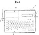
- a keyboard 3 is disposed in the front part of a frame 2 of the tape printing apparatus 1.
- a print mechanism PM At the back of the keyboard 3 and inside the frame 2 is a print mechanism PM.
- a liquid-crystal display (LCD) 22 At the back of the keyboard 3 is a liquid-crystal display (LCD) 22 capable of displaying characters and symbols.
- the keyboard 3 comprises character keys for inputting alphabetic characters, hiragana characters, numerals and symbols; a space key; a return key; cursor movement keys for moving a cursor K back and forth on the LCD 22; a format setting key for setting a print format; a size setting key for setting the size of print characters; a font setting key for setting the font of print characters; a text print key for designating the printing of text; a scale print key for designating scale printing; a tape feed key for feeding a printing tape 5; and a power key for turning on and off power.
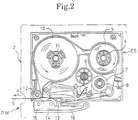
- a rectangular tape-storage cassette CS is loaded removably in the print mechanism PM.
- the tape-storage cassette CS contains a tape spool 6 around which the printing tape 5 about 18 mm wide is wound; a ribbon feed spool 8 around which an ink ribbon 7 is wound; a take-up spool 9 that takes up the ink ribbon 7; a feed spool 11 around which an adhesive double-coated tape 10 is wound with its peeling sheet facing outward; and a bonding roller 12 that bonds the printing tape 5 to the adhesive double-coated tape 10.
- the roller and the spools are furnished rotatably.
- a thermal head 13 is positioned where the printing tape 5 and the ink ribbon 7 overlap.
- a platen roller 14 and a feed roller 15 are attached pivotably to a support body 16. The platen roller 14 presses the printing tape 5 and ink ribbon 7 against the thermal head 13, and the feed roller 15 pushes the printing tape 5 and adhesive double-coated tape 10 against the bonding roller 12.
- the thermal head 13 has a group of 128 heating elements arranged vertically thereon.
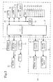
- the block diagram of Fig. 3 shows how the control system of the tape printing apparatus 1 is structured.
- the I/O interface 27 of a controller C is connected with a liquid-crystal display controller (LCDC) 23 that outputs display data to the LCD 22, a driving circuit 25 that drives the thermal head 13, a driving circuit 26 that drives the tape feed motor 24, and a driving circuit 21 that drives a warning buzzer 20.
- the controller C comprises a CPU 29, the I/O interface 27 connected to the CPU 29 via a bus arrangement 28 including a data bus; a CGROM 30, ROM's 31 and 32, and a RAM 40.
- the CGROM (pattern data memory) 30 stores dot pattern data representing numerous characters and corresponding to the code data about the characters for display.
- the ROM (outline data memory) 31 stores outline data classified by font (Gothic, Mincho, etc.) and defining the outlines of numerous characters to be printed, the data corresponding to the code data about the characters.
- the ROM 32 contains a display driving control program, an image development processing control program, a print driving control program and a tape print control program.
- the display driving control program controls the display controller 23 in accordance with the code data about the characters, numerals and symbols entered from the keyboard 3.
- the image development processing control program converts to dot pattern data the outline data corresponding to the code data in a text memory 41, and develops the dot pattern data in a print buffer 47 for printing.
- the print driving control program reads consecutively the data of the print buffer 47 and drives the thermal head 13 and tape feed motor 24 accordingly.
- the print control program is specific to this invention and will be described later in more detail.
- the image development processing control program includes various subroutines for controlling character modifications such as bold typeface and white-on-black character printing.
- the RAM 40 includes the text memory 41, a print format memory 42, a scale length memory 43, a graduation line pitch memory 44, a numeral unit memory 45, a division counter 46, the print buffer 47 and a flag memory 48.
- the text memory 41 (corresponding to the input data storage means) stores as text data the code data representing the characters and symbols entered from the keyboard 3.
- the print format memory 42 contains data about a plurality of print formats.
- the data in the print format memory 42 include the data for defining the established character size, the data for defining the font, and modification data for the characters selected.
- the scale length memory 43 stores, in millimeters, the entire length SL of the scale designated.
- the graduation line pitch memory 44 accommodates the unit pitch (m, cm, mm) of the graduation lines of the scale selected, the pitch of small graduation lines SmL equivalent to unit divisions, the pitch of medium graduation lines ML provided at intervals of five unit divisions, and the pitch of large graduation lines LL provided at intervals of 10 unit divisions.
- the numeral unit memory 45 stores numeral unit data "11" for a unit length of one meter (m), "10” for one centimeter (cm) and "01" for one millimeter (mm), the unit data representing the numeral unit, i.e., the length unit indicated by the division numeral selected.
- the division counter 46 contains a count value SC representing the number of all the divisions on the scale.
- the print buffer 47 accommodates the dot pattern data representing a plurality of characters and symbols developed as images for printing, as well as the dot pattern data for scale printing.
- the print buffer 47 has memory capacities of 128 bits (16 bites) corresponding to 128 dots in the vertical direction (dot column direction) and an appropriate number of bits corresponding to a plurality of characters in the horizontal direction (dot row direction).
- the flag memory 48 stores flag data representing a large division numeral flag LF set (to "1") when division numerals are printed to large graduation lines LL, flag data representing a medium division numeral flag MF set when division numerals are printed to medium graduation lines ML, and flag data representing a small division numeral flag SF set when division numerals are printed to small graduation lines SmL.
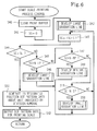
- step 10 Operating the power key supplies power and starts the tape print control program whose steps are shown in Fig. 4.
- step 10 the memories 41 through 48 are cleared for initialization (step 10). If a key input is detected and if the key operated is a text-related key, such as a character key or a symbol key (YES in steps 11 and 12), the input character code is stored into the text memory 41 (step 13). The character or symbol represented by that character code is displayed on the LCD 22 (step 14) and step S11 is reached again.
- a text-related key such as a character key or a symbol key
- step 16 a text printing process is carried out to print the text data stored in the text memory 41 (step 16) and step S11 is reached again.
- the text printing process is an ordinary printing process executed as follows: the dot pattern data corresponding to the character codes are read from the text memory 41 and are developed into the dot pattern data for printing according to the character size and font designated. The developed dot pattern data for printing are accommodated in the print buffer 47. The dot pattern data are then read from the print buffer 47 for output to the print mechanism PM that prints the data successively onto the printing tape 5.
- the LCD 22 displays a division numeral setting screen in which to designate or deny the need for printing division numerals in conjunction with the large, medium and/or small graduation lines LL, ML and/or SmL. Also designated on the division numeral setting screen is the length unit to be indicated by the division numerals (step 35).
- a cursor movement key (forward or backward) permits the selection and establishment of the unit length dimension (i.e., mm, cm, m, or inch) of the graduation lines to which the division numerals are to be printed. Pushing the return key sets the division numeral flag LF, MF or SF corresponding to the graduation lines in conjunction with which of the division numerals are designated, and stores the data about the designated numeral unit into the numeral unit memory 45 (step 36).
- Step 36 is followed by step 19 of the tape printing control process wherein scale printing is executed.
- the division numeral setting screen such as that of Fig. 12 appears on the LCD 22.
- the large graduation lines LL are illustratively designated by use of the division numeral unit (cm). This means that it is the large graduation lines to which the division numerals are printed in an accompanying manner.
- An entry "OFF" is made for each of the medium and small graduation lines ML and SmL to which division numerals are not printed.
- the large division numeral flag LF is set, and the unit data "10" is stored into the numeral unit memory 45.
- the print buffer 47 is cleared (step 40).
- An initial value "0" is set as the count value SC to the division counter 46 (step 41).
- the control process of developing large graduation lines is carried out because the scale usually begins with a large graduation line LL (step 42).
- the count value SC of 0 corresponds to the first position (i.e., leftmost position) in the print buffer 47.
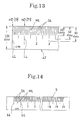
- the dot pattern data representing the large graduation line LL that is two dot columns wide and about 80 dots long (step 61) is developed.
- the count value SC is 0 as shown in Fig. 13
- the dot pattern data representing the large graduation line LL are developed in the nD [0] position, i.e., in the leftmost position of the print buffer 47.
- step 62 If the large division numeral flag LF is found to be set (YES in step 62), and if the extension of the large graduation line LL has enough space to accommodate the developed dot pattern data on the division numeral of the designated character size (YES in step 63), the dot pattern data on the division numeral are developed as per the unit data stored in the numeral unit memory 45 so that the designated character size will be established (step 64). Step 64 is followed by step 43 for the scale printing process.
- the large division numeral flag LF is found not to be set (NO in step 62), and if the dot pattern data on the division numeral cannot be developed (NO in step 63), the large graduation line development process is terminated immediately.
- the count value SC is 0 and the position nD is 0 as shown in Fig. 13, there is no space in which to develop the dot pattern data for the division numeral.
- the count value SC is, say, 10 and the position nD is 71, there is enough space in which to develop the dot pattern data of a division numeral 1.
- step 43 the count value SC is incremented by 1 (step 43). If the count value is less than the scale length SL (NO in step 44), and if the count value SC is an integer multiple N of the large graduation line pitch LP (YES in step 45), the above-mentioned large graduation line development process is carried out (step 46). Step 46 is followed by step 43. If the count value SC is an integer multiple N of the medium graduation line pitch MP (NO in step 45, YES in step 47), the process of medium graduation line development control (see Fig. 8) is carried out (step 48). Step 48 is followed by step 43. The process of medium graduation line development control is approximately the same as that of large graduation line development control described above.
- the developing position nD for the medium graduation line ML corresponding to the count value SC in the print buffer 47 is first obtained (step 70).
- the dot pattern data on the medium graduation line ML that is two dot columns wide and about 68 dots long are developed.
- step 50 the process of small graduation line development control (see Fig. 9) is carried out (step 50).
- step 50 is followed by step 43.
- the process of small graduation line development control is approximately the same as that of large graduation line development control as described above.
- the developing position nD for the small graduation line SmL corresponding to the count value SC in the print buffer 47 is first obtained (step 80).
- the dot pattern data on the small graduation line SmL that is two dot columns wide and about 48 dots long are developed.
- step 84 is followed by step S43 for the scale printing process. If the small division numeral flag SF is found not to be set (NO in step 82), and if the printing of the division numeral is not possible (NO in step 83), the process of small graduation line development control is terminated immediately.
- the dot pattern data on the unit indicated by the division numeral are developed in the designated position of the print buffer 47 (step 51).
- the dot pattern data for scale printing are then read consecutively from the print buffer 47 for output to the print mechanism PM, and the print mechanism PM prints the scale accordingly (step 52).
- Step 52 is followed by step 11 of the tape printing control process.
- the print buffer 47 contains the dot pattern data for scale printing made illustratively of a plurality of large, medium and small graduation lines LL, ML and SmL as well as division numerals 1, 2, 3, etc. It is according to these dot pattern data that the print mechanism PM prints the scale onto the printing tape 5, as depicted in Fig. 14.
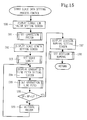
- the above-described scale data setting process may be modified partially in which the pitch of the graduation lines LL, ML or SmL on the scale is corrected to compensate for the feed error of the printing tape 5, as outlined in Fig. 15. This modification aims at improving the precision of the scale printed.
- routines common to the above-described process will be omitted and only those different therefrom will be described.
- the LCD 22 first displays a correction factor setting screen which is used to correct the graduation line pitch in accordance with the feed error of the printing tape 5 (step 90).
- Numeric keys on the keyboard 3 are operated to designate the appropriate correction factor.
- Pushing the return key stores the correction factor data into a work memory of the RAM 40 (step 91).
- the scale length, the graduation line pitch and the division numerals are set in the manner described (steps 92 through 98).
- the scale data setting process of Fig. 15 completed, the scale printing process of Fig. 6 starts to be executed.
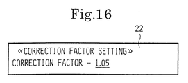
- the correction factor setting screen such as that of Fig. 16 is displayed on the LCD 22. In this screen, numeric keys are operated to enter, for example, 1.05 into the underlined input field.
- the developing positions nD for the graduation lines LL, ML and SmL are acquired respectively in step 60 (of the large graduation line development process) following step 46, in step 70 (of the medium graduation line development process) following step 48, and in step 80 (of the small graduation line development process) following step 49.
- the dot pattern data on the graduation lines LL, ML and SmL are developed in the respective developing positions nD.
- the scale with its graduation line pitch set approximately at 1 mm is printed on the printing tape 5.
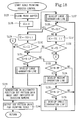
- the scale data setting process and the scale printing process may be modified partially as outlined in Figs. 17 and 18. In these modifications, the starting and ending graduation lines of the scale may be set as desired. It is also possible to print the division numerals in descending order. In the description that follows, the routines common to the above-described scale data setting process will be omitted and only those different therefrom will be described.
- the LCD 22 When the scale data setting process is started, the LCD 22 first displays a scale range setting screen in which to designate the desired range of the scale to be printed (step 110). On the keyboard 3, numeric keys are operated to set a start-of-scale value SS and an end-of-scale value ES. Pushing the return key enters the two values SS and ES into the work memory of the RAM 40 (step 111).
- step 112 If the absolute difference between the start-of-scale value SS and the end-of-scale value ES is equal to or less than the maximum scale length AL that may be created in the print buffer 47 (YES in step 112), the graduation line pitches and the division numerals are set consecutively (steps 113 through 117). With the scale data setting process concluded, the scale printing process of Fig. 18 is started. If the absolute difference between the start-of-scale value SS and the end-of-scale value ES is greater than the maximum scale length AL that may be created in the print buffer 47 (NO in step 112), the buzzer 20 is activated for warning (step 118), and step 111 is reached. For example, when the scale range setting screen is displayed on the LCD 22, numeric keys are operated to enter, say, 600 and 300 (mm) respectively into the start-of-scale and end-of-scale value fields underlined, as shown in Fig. 19.
- steps 125 and 126 are followed by the dot pattern data developing process for the first large graduation line LL (step 127). If the start-of-scale value SS is smaller than the end-of-scale value ES (YES in step 128), the count value SC is incremented by 1 (step 129). If the count value SC is smaller than the end-of-scale value ES (NO in step 130), step 131 is reached. If the start-of-scale value SS is greater than the end-of-scale value ES (NO in step 128), the count value SC is decremented by 1 (step 137). If the count value SC is greater than the end-of-scale value ES (NO in step 138), step 131 is reached.
- step 139 the dot pattern data for the unit dimension, represented by the division numeral, are developed in step 139.
- step' 140 the dot pattern data for scale printing are read consecutively from the print buffer 47 for output to the print mechanism PM whereby the scale is printed.
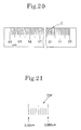
- the scale having a starting division of 60 cm and an ending division of 30 cm is printed on the printing tape 5.
- the graduation line pitch is set for "mm,” the small graduation line pitch SP for "1,” the medium graduation line pitch MP for "5" and the large graduation line pitch LP for "10.”
- the data about the dot pattern DP representing a basic repeatable length (e.g., 0.00 to 0.999 cm at which to print scale graduation lines LL, ML and SmL) may be stored beforehand in a nonvolatile memory such as the ROM 32.
- the stored data are matched with a plurality of combinations of the graduation line pitch, small graduation line pitch SP, medium graduation line pitch MP and large graduation line pitch LP.
- the data about the basic length dot pattern DP may be repeated as many times as needed to generate in the print buffer 47 the dot pattern data necessary for creating the desired scale.
- the scale data setting process may be arranged to set the print positions of division numerals as well as the print positions of the length units indicated by the division numerals.
- the metric system adopted for printing by the embodiment above may be replaced with the inch system or any other measuring system.
- a plurality of setting items such as the scale length may be displayed in a menu format; the contents of the selected items may be displayed successively using cursor movement keys; or any other display-and-input techniques may be utilized for ease of operation.
- Graduation line printing may be carried out by use of different line widths for the small, medium and large graduation lines. For example, printing the small graduation lines SmL thin, the large graduation lines LL thick and the medium graduation lines ML with an intermediate thickness enhances the appearance of the printed scale. It is possible to store beforehand the line thicknesses of the graduation lines in a ROM; each graduation line type may be set for a desired thickness value stored in advance. As another variation, it may be arranged that establishing the line thickness for one graduation line type will automatically set the line thicknesses of the remaining graduation line types.
- the block diagram of Fig. 22 shows how the control system of the tape printing apparatus of the second embodiment is structured.
- the I/O interface 127 of a controller D is connected with a liquid-crystal display controller (LCDC) 23 that outputs display data to the LCD 122, a driving circuit 125 that drives the thermal head 113, a driving circuit 126 that drives the tape feed motor 124, and a driving circuit 121 that drives a warning buzzer 120.
- the controller D comprises a CPU 129, the I/O interface 127 connected to the CPU 129 via a bus arrangement 128 including a data bus, a CGROM 130, ROM's 131 and 132, and a RAM 140.
- the CGROM (pattern data memory) 130 stores dot pattern data representing numerous characters and corresponding to the code data about the characters for display.
- the ROM (outline data memory) 31 stores outline data classified by font (Gothic, Mincho, etc.) and defining the outlines of numerous characters to be printed, the data corresponding to the code data about the characters.
- the ROM 132 contains a display driving control program, an image development processing control program, a print driving control program and a tape print control program.
- the display driving control program controls the display controller 123 in accordance with the code data about the characters, numerals and symbols entered from the keyboard 103.
- the image development processing control program converts to dot pattern data the outline data corresponding to the code data in a text memory 141, and develops the dot pattern data in a print buffer 148 for printing.
- the print driving control program reads consecutively the data of the print buffer 148 and drives the thermal head 113 and tape feed motor 124 accordingly.
- the print control program is specific to this invention and will be described later in more detail.
- the image development processing control program includes various subroutines for controlling character modifications such as bold typeface and white-on-black character printing.
- the RAM 140 includes the text memory 141, a print format memory 142, a scaling factor memory 143, a scale length memory 144 and a graduation line pitch memory 145.
- the text memory 141 (corresponding to the input data storage means) stores as text data the code data representing the characters and symbols entered from the keyboard 103.
- the print format memory 142 contains data about a plurality of print formats. The data in the print format memory 142 include data for defining the character size established, data for defining the font, and modification data for the characters selected.
- the scaling factor memory 143 accommodates the scaling factor (for contraction or magnification) of the scale designated.
- the scale length memory 144 stores in millimeters the entire length SL of the scale designated.
- the graduation line pitch memory 145 stores the pitch of small graduation lines SmL equivalent to unit divisions, the pitch of medium graduation lines ML provided at intervals of five unit divisions, and the pitch of large graduation lines LL provided at intervals of 10 unit divisions.
- the RAM 140 also includes a minimum pitch memory 146, a division counter 147, a print buffer 148 and a flag memory 149.
- the minimum pitch memory 146 accommodates data ⁇ about the minimum graduation line pitch calculated.
- the division counter 147 contains a count value SC representing the number of all the divisions on the scale.
- the print buffer 148 accommodates the dot pattern data representing a plurality of characters and symbols developed as images for printing, as well as the dot pattern data for scale printing. To serve its purpose, the print buffer 148 has memory capacities of 128 bits (16 bites) corresponding to 128 dots in the vertical direction (dot column direction) and an appropriate number of bits corresponding to a plurality of characters in the horizontal direction (dot row direction).
- the flag memory 149 stores flag data representing a large division numeral flag LF set (to "1") when division numerals are printed to large graduation lines LL, flag data representing a medium division numeral flag MF set when division numerals are printed to medium graduation lines ML, and flag data representing a small division numeral flag SF set when division numerals are printed to small graduation lines SmL.
- step 210 Operating the power key supplies power and starts the tape print control program whose steps are shown in Fig. 23.
- the memories 141 through 149 are cleared for initialization (step 210). If a key input is detected and if the key operated is a text-related key such as a character key or a symbol key (YES in steps 211 and 212), the input character code is stored into the text memory 141 (step 213). The character or symbol represented by that character code is displayed on the LCD 122 (step 214) and step S211 is reached again.
- a text-related key such as a character key or a symbol key
- step 216 a text printing process is carried out to print the text data stored in the text memory 141 (step 216) and step S211 is reached again.
- the text printing process is an ordinary printing process executed as follows: the dot pattern data corresponding to the character codes are read from the text memory 141 and are developed into the dot pattern data for printing according to the character size and font designated. The developed dot pattern data for printing are accommodated in the print buffer 148. The dot pattern data are then read from the print buffer 148 for output to the print mechanism PM1 that prints the data successively onto the printing tape 105.
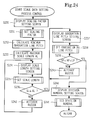
- a scale data setting process (Fig. 24) is carried out wherein a plurality of setting data about the scale are input and established (step 218).
- a scale printing process (Fig. 25) is then carried out (step 219) before step 211 is reached again.
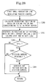
- a scaling factor setting screen (Fig. 29) in which to set a desired scaling factor is displayed on the LCD 122 (step 230).
- numeric keys are operated to set the scaling factor for contraction or magnification.
- pressing the return key enters the scaling factor data into the scaling factor memory 143 (step 231).
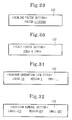
- the scaling factor setting screen of Fig. 29 is displayed on the LCD 122.
- the user enters illustratively a scaling factor of 1/100,000 for contraction into the underlined input field by operating numeric keys.
- the minimum graduation line pitch ⁇ is calculated (step 232).
- the dot pitch i.e., the dot diameter for printing by the print head is as small as 0.141 mm. This requires that for readability, each graduation line and the space between two adjacent graduation lines be expressed by at least three dot columns each.
- a unit scale length of 100 m is selected as the minimum graduation line pitch ⁇ .
- a maximum scale length AL that may be generated in the print buffer 48 is obtained (step 233).
- numeric keys are operated to set the desired scale length SL in scale length units. Pressing the return key sets the scale length data to the scale length memory 144 (step 235). For example, the scale length setting screen, such as that of Fig. 30, appears on the LCD 122. The user then sets, say, 30 km into the input field underlined using numeric keys.
- the buzzer 220 is activated (step 242) as a warning. Then, the scale length setting screen is again displayed (step 234). If the scale length SL is less than the maximum scale length AL (YES in step 236), the LCD 122 displays a graduation line pitch setting screen (step 237). On this screen, numeric keys are operated to set a pitch LP of large graduation lines LL, a pitch MP of medium graduation lines ML and a pitch SP of small graduation lines SmL, all based on the minimum graduation line pitch ⁇ . Pushing the return key stores the data on the graduation line pitches LP, MP and SP into the graduation line pitch memory 145 (step 238).
- the small graduation line pitch SP is usually equivalent to one minimum graduation line pitch ⁇ , the medium graduation line pitch MP to five minimum graduation line pitches, and the large graduation line pitch LP to 10 minimum graduation line pitches.
- the graduation line pitch setting screen of Fig. 31 is displayed on the LCD 122. Referring to the minimum graduation line pitch ⁇ indicated (e.g., 100 m), the user operates numeric keys to set "10" to the item LARGE (pitch of large graduation lines LL), "5" to the item MEDIUM (pitch of medium graduation line ML) and “1" to the item SMALL (pitch of small graduation lines SML). Other settings than “10", "5", and "1" may also be made.
- the following condition needs to be met: SP ⁇ MP ⁇ LP; where SP stands for the large graduation line pitch, MP for the medium graduation line pitch, and SP for the small graduation line pitch. If the above condition is not met (NO in step 239), the buzzer 120 is activated (step 242) for warning and the graduation line pitch setting screen is again displayed (step 237). If the above condition is found to be met (YES in step 239), the LCD 122 displays a division numeral setting screen in which to designate or deny the need for printing division numerals in conjunction with the large, medium and/or small graduation lines LL, ML and/or SmL. Also designated on the division numeral setting screen is the length unit to be indicated by division numerals (step 240).
- a cursor movement key selects and establishes the graduation lines to which division numerals are to be printed in an accompanying manner, the lines being indicated on the display by an integer multiple of the minimum graduation line pitch ⁇ .
- Pushing the return key sets a division numeral flag LF, MF or SF corresponding to the graduation lines LL, ML or SmL to which the division numerals are to be printed (step 241).
- step 219 of the tape print control program is reached in which the scale is printed.
- the division numeral setting screen appears on the LCD 22.
- the large graduation lines LL are illustratively designated by use of an integer multiple "x 10" of the minimum graduation line pitch ⁇ . This means that it is the large graduation lines to which the division numerals are printed in an accompanying manner.
- An entry "OFF" is made for each of the medium and small graduation lines ML and SmL to which division numerals are not printed. Thus, only the large division numeral flag LF is set.
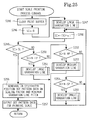
- the developing position nD of the large graduation line LL corresponding to the count value SC in the print buffer 148 is obtained (step 260).
- the count value SC of 0 corresponds to the first position (i.e., leftmost position) in the print buffer 148.
- the dot pattern data representing the large graduation line LL that is two dot columns wide and about 80 dots long (step 261) are developed.
- the count value SC is 0, as shown in Fig. 34
- the dot pattern data representing the large graduation line LL is developed in the nD [0] position, i.e., in the leftmost position of the print buffer 148.
- step 264 If the large division numeral flag LF is found to be set (YES in step 262), and if the extension of the large graduation line LL has enough space to accommodate the developed dot pattern data on the division numeral of the designated character size (YES in step 263), the dot pattern data on the division numeral are developed so as to attain the designated character size (step 264).
- the developing of the dot pattern data is carried out according to the integer multiple and count value SC designated for the large graduation lines LL.
- the value obtained by dividing the count value SC by the multiple of graduations for spacing between the graduation lines (SmL, ML, LL) is the numeral used to identify the particular graduation line.
- Step 264 is followed by step 248 for the scale printing process.
- the large division numeral flag LF is found not to be set (NO in step 262), and if the dot pattern data on the division numeral cannot be developed (NO in step 263), the large graduation line developing process is terminated immediately.
- the count value SC is 0 and the position nD is 0, as shown in Fig. 33, there is no space in which to develop the dot pattern data for the division numeral.
- the count value SC is, say, 10 and a second large graduation line LL is in effect (i.e., X is set for position nD), there is enough space in which to develop the dot pattern data on a division numeral 1.
- step 248 the count value SC is incremented by one minimum graduation line pitch ⁇ (step 248). If the count value is less than the scale length SL (NO in step 249), and if the count value SC is an integer multiple N of the large graduation line pitch LP (YES in step 250), the above-mentioned large graduation line developing process is carried out (step 251). Step 251 is followed by step 248. If the count value SC is an integer multiple N of the medium graduation line pitch MP (NO in step 250, YES in step 252), the process of medium graduation line development control (see Fig. 27) is carried out (step 253). Step 253 is followed by step 248. The process of medium graduation line development control is approximately the same as that of large graduation line development control described above.
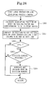
- the developing position nD for the medium graduation line ML is first obtained on the basis of the scaling factor data (step 270).
- the dot pattern data on the medium graduation line ML that is two dot columns wide and about 68 dots long are developed.
- step 272 If the medium division numeral flag MF is found to be set (YES in step 272), and if there is enough space in which to develop the dot pattern data for the numeral of the designated character size (YES in step 273), the dot pattern data on the division numeral are developed so as to attain the designated character size (step 274). Step 274 is followed by step S248 for the scale printing process. If the medium division numeral flag MF is found not to be set (NO in step 272), and if the printing of the division numeral is not possible (NO in step 273), the process of medium graduation line development control is terminated immediately.
- step 255 is followed by step 248.
- the process of small graduation line development control is approximately the same as that of large graduation line development control described above. Briefly, the developing position nD for the small graduation line SmL is first obtained on the basis of the scaling factor data (step 280). In this developing position nD, the dot pattern data on the small graduation line SL that is two dot columns wide and about 48 dots long (step 281) are developed.
- the dot pattern data on the scaling factor and those on the minimum graduation line pitch ⁇ are developed in the designated positions of the print buffer 148 (step 256).
- the dot pattern data for scale printing are read consecutively from the print buffer 148 for output to the print mechanism PM1, and the print mechanism PM1 prints the scale accordingly (step 257).
- Step 257 is followed by step 211 of the tape printing control process.
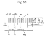
- the print buffer 148 contains the dot pattern data for scale printing made illustratively of a plurality of large, medium and small graduation lines LL, ML and SmL as well as division numerals 1, 2, 3, etc. It is according to these dot pattern data that the print mechanism PM1 prints the scale of the designated scaling factor onto the printing tape 105, as depicted in Fig. 34.
- a scaling factor of 1,000 is set in the above-described scale data setting process, a value of 0.01 ⁇ m is obtained as the minimum graduation line pitch data ⁇ .
- the scale based on the scaling factor of 1,000 is then printed on the printing tape 105 as shown in Fig. 35.
- the minimum graduation line pitch of a desired scaling factor is obtained as the pitch representing the unit length of the scale. It is then possible to produce easily and inexpensively the scale of any designated scaling factor based on that minimum graduation line pitch, with graduation lines printed in an accurate and orderly manner. The minimum graduation line pitch is kept from getting too small to be practical for the scale to be printed.
- the metric system adopted for printing by the embodiment above may be replaced with the English system using inches or any other measuring system.
- a plurality of setting items including the scale length may be displayed in a menu format, and the contents of the selected items may be displayed successively using cursor movement keys. It is not mandatory to set the three kinds of graduation lines (large, medium and small) all at once. Alternatively, any combination of the three line types, e.g., large and small, medium and small, or small only, may be selected and established as desired.
Landscapes
- Printers Characterized By Their Purpose (AREA)
Applications Claiming Priority (4)
| Application Number | Priority Date | Filing Date | Title |
|---|---|---|---|
| JP258925/92 | 1992-09-01 | ||
| JP25892592A JPH0679925A (ja) | 1992-09-01 | 1992-09-01 | スケール印刷装置 |
| JP26306692A JPH0679926A (ja) | 1992-09-03 | 1992-09-03 | スケール印刷装置 |
| JP263066/92 | 1992-09-03 |
Publications (2)
| Publication Number | Publication Date |
|---|---|
| EP0586164A2 true EP0586164A2 (fr) | 1994-03-09 |
| EP0586164A3 EP0586164A3 (fr) | 1995-01-25 |
Family
ID=26543887
Family Applications (1)
| Application Number | Title | Priority Date | Filing Date |
|---|---|---|---|
| EP93306659A Withdrawn EP0586164A3 (fr) | 1992-09-01 | 1993-08-23 | Appareil d'impression d'une échelle de graduation. |
Country Status (3)
| Country | Link |
|---|---|
| US (1) | US5435659A (fr) |
| EP (1) | EP0586164A3 (fr) |
| KR (1) | KR940006782A (fr) |
Cited By (1)
| Publication number | Priority date | Publication date | Assignee | Title |
|---|---|---|---|---|
| CN113267114A (zh) * | 2021-05-21 | 2021-08-17 | 郭政 | 一种量角系统和方法 |
Families Citing this family (12)
| Publication number | Priority date | Publication date | Assignee | Title |
|---|---|---|---|---|
| US5595450A (en) * | 1992-06-11 | 1997-01-21 | Esselte N.V. | Label printing apparatus with display |
| US6092947A (en) * | 1992-10-06 | 2000-07-25 | Seiko Epson Corporation & King Jim Co., Ltd. | Tape printing device |
| CA2107759A1 (fr) * | 1992-10-06 | 1994-04-07 | Masahiko Nunokawa | Dispositif d'impression de bande |
| US5836061A (en) * | 1997-07-12 | 1998-11-17 | Honda Giken Kogyo Kabushiki Kaisha | Cable end anchoring nipple and methods of constructing and utilizing same |
| JP3349577B2 (ja) | 1993-12-30 | 2002-11-25 | セイコーエプソン株式会社 | 印字装置 |
| JP3397995B2 (ja) * | 1996-11-07 | 2003-04-21 | セイコーエプソン株式会社 | テープ印刷装置 |
| US6128097A (en) * | 1996-12-18 | 2000-10-03 | Schlumberger Technology Corporation | Apparatus, system and method for calibrating the longitudinal accuracy of printers |
| KR100536836B1 (ko) * | 2004-01-14 | 2005-12-16 | 삼성전자주식회사 | 스캐너 및 그의 스케일 표시방법 |
| WO2005086882A2 (fr) * | 2004-03-10 | 2005-09-22 | Kroy Llc | Dispositif d'impression sur bande et procede d'impression |
| KR100663347B1 (ko) * | 2004-12-21 | 2007-01-02 | 삼성전자주식회사 | 중첩도 측정마크를 갖는 반도체소자 및 그 형성방법 |
| GB0706785D0 (en) * | 2007-04-05 | 2007-05-16 | Dymo Nv | Tape printing apparatus |
| JP6511597B2 (ja) * | 2015-07-13 | 2019-05-15 | 和則 川島 | 目盛 |
Family Cites Families (8)
| Publication number | Priority date | Publication date | Assignee | Title |
|---|---|---|---|---|
| US4051774A (en) * | 1976-05-17 | 1977-10-04 | Jack Barnes Engineering, Inc. | Machine for printing measuring tapes |
| DE3416013C2 (de) * | 1984-04-30 | 1991-01-03 | Volker Dipl.-Ing. 3548 Arolsen Meywald | Verfahren und Vorrichtung zur Herstellung von Längenmeßgeräten |
| JPS61140801A (ja) * | 1984-12-13 | 1986-06-27 | Sekisui Jushi Co Ltd | 小交を有する鋼製巻尺テ−プの製造方法 |
| JPH0634126Y2 (ja) * | 1987-11-28 | 1994-09-07 | ブラザー工業株式会社 | 剥離紙付き印字テープ切断機構を備えた印字装置 |
| JPH02106555A (ja) * | 1988-10-14 | 1990-04-18 | Brother Ind Ltd | テープ収納カセット |
| JPH0433784A (ja) * | 1990-05-26 | 1992-02-05 | Hasegawa Seisakusho:Kk | 金属尺の目盛付加法 |
| MY124305A (en) * | 1991-01-31 | 2006-06-30 | Casio Computer Co Ltd | Tape printer. |
| JP2536322B2 (ja) * | 1991-03-28 | 1996-09-18 | ブラザー工業株式会社 | テ―プ印字装置 |
-
1993
- 1993-07-16 US US08/092,492 patent/US5435659A/en not_active Expired - Lifetime
- 1993-08-23 EP EP93306659A patent/EP0586164A3/fr not_active Withdrawn
- 1993-08-31 KR KR1019930017091A patent/KR940006782A/ko not_active Abandoned
Cited By (2)
| Publication number | Priority date | Publication date | Assignee | Title |
|---|---|---|---|---|
| CN113267114A (zh) * | 2021-05-21 | 2021-08-17 | 郭政 | 一种量角系统和方法 |
| CN113267114B (zh) * | 2021-05-21 | 2023-04-07 | 郭政 | 一种量角系统和方法 |
Also Published As
| Publication number | Publication date |
|---|---|
| KR940006782A (ko) | 1994-04-25 |
| US5435659A (en) | 1995-07-25 |
| EP0586164A3 (fr) | 1995-01-25 |
Similar Documents
| Publication | Publication Date | Title |
|---|---|---|
| US5595450A (en) | Label printing apparatus with display | |
| US5314256A (en) | Printing device | |
| EP0577247B1 (fr) | Dispositif pour l'impression sur rubans | |
| US5435659A (en) | Scale printing apparatus | |
| EP0577250B1 (fr) | Dispositif d'impression de bande | |
| JP2629516B2 (ja) | テープ印字装置 | |
| EP0440497A2 (fr) | Appareil de traitement de documents comportant un système de commande du layout de l'affichage | |
| EP0855283B1 (fr) | Appareil pour l'impression d'étiquettes | |
| JP3098636B2 (ja) | テープ印刷装置及び方法 | |
| JP2959388B2 (ja) | ラベル印刷方法 | |
| JP2667084B2 (ja) | ラベル印字装置 | |
| JP2667091B2 (ja) | ラベル印字装置 | |
| JP2642020B2 (ja) | ラベル印字装置 | |
| EP0573262A1 (fr) | Appareil de traitement de textes | |
| JP2798854B2 (ja) | ラベル印字装置 | |
| JP2718602B2 (ja) | ラベル印字装置 | |
| JP2703458B2 (ja) | ラベル印字装置 | |
| JP2703461B2 (ja) | ラベル印字装置 | |
| JP3139514B2 (ja) | テープ印字装置 | |
| JP3118999B2 (ja) | スケール印刷装置 | |
| JP2667093B2 (ja) | ラベル印字装置 | |
| JP2667085B2 (ja) | ラベル印字装置 | |
| JP2667092B2 (ja) | ラベル印字装置 | |
| JP2690665B2 (ja) | ラベル印字装置 | |
| JP2667090B2 (ja) | ラベル印字装置及びこの装置におけるラベル情報登録方式 |
Legal Events
| Date | Code | Title | Description |
|---|---|---|---|
| PUAI | Public reference made under article 153(3) epc to a published international application that has entered the european phase |
Free format text: ORIGINAL CODE: 0009012 |
|
| AK | Designated contracting states |
Kind code of ref document: A2 Designated state(s): BE DE FR GB |
|
| PUAL | Search report despatched |
Free format text: ORIGINAL CODE: 0009013 |
|
| AK | Designated contracting states |
Kind code of ref document: A3 Designated state(s): BE DE FR GB |
|
| 17P | Request for examination filed |
Effective date: 19950602 |
|
| 17Q | First examination report despatched |
Effective date: 19950710 |
|
| STAA | Information on the status of an ep patent application or granted ep patent |
Free format text: STATUS: THE APPLICATION IS DEEMED TO BE WITHDRAWN |
|
| 18D | Application deemed to be withdrawn |
Effective date: 19970515 |