EP0586172A2 - Motorisiertes schwenkbares Werkzeug mit Tisch - Google Patents
Motorisiertes schwenkbares Werkzeug mit Tisch Download PDFInfo
- Publication number
- EP0586172A2 EP0586172A2 EP93306680A EP93306680A EP0586172A2 EP 0586172 A2 EP0586172 A2 EP 0586172A2 EP 93306680 A EP93306680 A EP 93306680A EP 93306680 A EP93306680 A EP 93306680A EP 0586172 A2 EP0586172 A2 EP 0586172A2
- Authority
- EP
- European Patent Office
- Prior art keywords
- frame
- power tool
- axis
- wheel
- pivot
- Prior art date
- Legal status (The legal status is an assumption and is not a legal conclusion. Google has not performed a legal analysis and makes no representation as to the accuracy of the status listed.)
- Granted
Links
Images


Classifications
-
- B—PERFORMING OPERATIONS; TRANSPORTING
- B23—MACHINE TOOLS; METAL-WORKING NOT OTHERWISE PROVIDED FOR
- B23Q—DETAILS, COMPONENTS, OR ACCESSORIES FOR MACHINE TOOLS, e.g. ARRANGEMENTS FOR COPYING OR CONTROLLING; MACHINE TOOLS IN GENERAL CHARACTERISED BY THE CONSTRUCTION OF PARTICULAR DETAILS OR COMPONENTS; COMBINATIONS OR ASSOCIATIONS OF METAL-WORKING MACHINES, NOT DIRECTED TO A PARTICULAR RESULT
- B23Q5/00—Driving or feeding mechanisms; Control arrangements therefor
-
- B—PERFORMING OPERATIONS; TRANSPORTING
- B27—WORKING OR PRESERVING WOOD OR SIMILAR MATERIAL; NAILING OR STAPLING MACHINES IN GENERAL
- B27B—SAWS FOR WOOD OR SIMILAR MATERIAL; COMPONENTS OR ACCESSORIES THEREFOR
- B27B5/00—Sawing machines working with circular or cylindrical saw blades; Components or equipment therefor
- B27B5/16—Saw benches
- B27B5/165—Convertible sawing devices
-
- A—HUMAN NECESSITIES
- A47—FURNITURE; DOMESTIC ARTICLES OR APPLIANCES; COFFEE MILLS; SPICE MILLS; SUCTION CLEANERS IN GENERAL
- A47B—TABLES; DESKS; OFFICE FURNITURE; CABINETS; DRAWERS; GENERAL DETAILS OF FURNITURE
- A47B77/00—Kitchen cabinets
- A47B77/04—Provision for particular uses of compartments or other parts ; Compartments moving up and down, revolving parts
- A47B77/10—Provision for particular uses of compartments or other parts ; Compartments moving up and down, revolving parts with members movable outwards to a position of use, e.g. tables, ironing boards
- A47B77/12—Provision for particular uses of compartments or other parts ; Compartments moving up and down, revolving parts with members movable outwards to a position of use, e.g. tables, ironing boards for attachment of portable kitchen machines
-
- B—PERFORMING OPERATIONS; TRANSPORTING
- B23—MACHINE TOOLS; METAL-WORKING NOT OTHERWISE PROVIDED FOR
- B23D—PLANING; SLOTTING; SHEARING; BROACHING; SAWING; FILING; SCRAPING; LIKE OPERATIONS FOR WORKING METAL BY REMOVING MATERIAL, NOT OTHERWISE PROVIDED FOR
- B23D47/00—Sawing machines or sawing devices working with circular saw blades, characterised only by constructional features of particular parts
- B23D47/02—Sawing machines or sawing devices working with circular saw blades, characterised only by constructional features of particular parts of frames; of guiding arrangements for work-table or saw-carrier
- B23D47/025—Sawing machines or sawing devices working with circular saw blades, characterised only by constructional features of particular parts of frames; of guiding arrangements for work-table or saw-carrier of tables
-
- B—PERFORMING OPERATIONS; TRANSPORTING
- B23—MACHINE TOOLS; METAL-WORKING NOT OTHERWISE PROVIDED FOR
- B23D—PLANING; SLOTTING; SHEARING; BROACHING; SAWING; FILING; SCRAPING; LIKE OPERATIONS FOR WORKING METAL BY REMOVING MATERIAL, NOT OTHERWISE PROVIDED FOR
- B23D47/00—Sawing machines or sawing devices working with circular saw blades, characterised only by constructional features of particular parts
- B23D47/132—Sawing machines or sawing devices working with circular saw blades, characterised only by constructional features of particular parts of means to position the saw blade at a specified angle when adjusting about an axis perpendicular to the work support surface
-
- B—PERFORMING OPERATIONS; TRANSPORTING
- B23—MACHINE TOOLS; METAL-WORKING NOT OTHERWISE PROVIDED FOR
- B23Q—DETAILS, COMPONENTS, OR ACCESSORIES FOR MACHINE TOOLS, e.g. ARRANGEMENTS FOR COPYING OR CONTROLLING; MACHINE TOOLS IN GENERAL CHARACTERISED BY THE CONSTRUCTION OF PARTICULAR DETAILS OR COMPONENTS; COMBINATIONS OR ASSOCIATIONS OF METAL-WORKING MACHINES, NOT DIRECTED TO A PARTICULAR RESULT
- B23Q1/00—Members which are comprised in the general build-up of a form of machine, particularly relatively large fixed members
- B23Q1/25—Movable or adjustable work or tool supports
- B23Q1/44—Movable or adjustable work or tool supports using particular mechanisms
- B23Q1/50—Movable or adjustable work or tool supports using particular mechanisms with rotating pairs only, the rotating pairs being the first two elements of the mechanism
- B23Q1/54—Movable or adjustable work or tool supports using particular mechanisms with rotating pairs only, the rotating pairs being the first two elements of the mechanism two rotating pairs only
- B23Q1/5468—Movable or adjustable work or tool supports using particular mechanisms with rotating pairs only, the rotating pairs being the first two elements of the mechanism two rotating pairs only a single rotating pair followed parallelly by a single rotating pair
-
- Y—GENERAL TAGGING OF NEW TECHNOLOGICAL DEVELOPMENTS; GENERAL TAGGING OF CROSS-SECTIONAL TECHNOLOGIES SPANNING OVER SEVERAL SECTIONS OF THE IPC; TECHNICAL SUBJECTS COVERED BY FORMER USPC CROSS-REFERENCE ART COLLECTIONS [XRACs] AND DIGESTS
- Y10—TECHNICAL SUBJECTS COVERED BY FORMER USPC
- Y10T—TECHNICAL SUBJECTS COVERED BY FORMER US CLASSIFICATION
- Y10T83/00—Cutting
- Y10T83/768—Rotatable disc tool pair or tool and carrier
- Y10T83/7684—With means to support work relative to tool[s]
- Y10T83/773—Work-support includes passageway for tool [e.g., slotted table]
-
- Y—GENERAL TAGGING OF NEW TECHNOLOGICAL DEVELOPMENTS; GENERAL TAGGING OF CROSS-SECTIONAL TECHNOLOGIES SPANNING OVER SEVERAL SECTIONS OF THE IPC; TECHNICAL SUBJECTS COVERED BY FORMER USPC CROSS-REFERENCE ART COLLECTIONS [XRACs] AND DIGESTS
- Y10—TECHNICAL SUBJECTS COVERED BY FORMER USPC
- Y10T—TECHNICAL SUBJECTS COVERED BY FORMER US CLASSIFICATION
- Y10T83/00—Cutting
- Y10T83/869—Means to drive or to guide tool
- Y10T83/8763—Convertible from tool path to another or from implement to machine
Definitions
- This invention relates to power tools, and particularly to saws, of the type mounted on a first side of a table adapted to move between two dispositions so that in a first disposition the tool is above the first side of the table and can be manipulated to work on workpieces supported on said first side, and in a second disposition, the tool is below the first side of the table, a working part thereof projecting through an aperture in the table to work on workpieces supported on a second side of the table.
- Such an arrangement is particularly effective for circular saws and was first described in DE-A-1628992.
- a saw is mounted on a table which is pivoted in a frame and flips over between two modes of operation, a first snip-off mode and a second bench saw mode.
- One of the benefits of such an arrangement is its versatility. Not only does it flip between two, quite different, modes of operation, but also it is mounted on a frame and arranged so that it is transportable. Ideally, it should be capable of being carried through a standard interior doorway and being carried in the boot of a common saloon car. Thus it can be carried to the site where it is needed. If it is light enough to be carried by one man, then so much the better.
- the table is pivoted in its middle, then the centre of gravity may move further away from the pivot by lengthening the table.
- the pivot can be moved nearer the back of the table (while remaining in the centre of the frame) but in this event, the table is no longer central on the frame. At least in one disposition, therefore, the long part of the table will be over the short part of the frame, and there will be a consequent overhang, which may be unbalanced or, at best, ergonomically unattractive.
- the table should be as thin as possible, so that the blade projects through it to the maximum possible extent in the bench saw mode. This therefore ensures that, in any practical arrangement, the pivot for the table will extend to one side or the other of the table. This cannot be permitted on the bench mode side because the pivot might interfere with movement on the table of larger workpieces such as sheet material. For the same reason it cannot be allowed on the snip-off-mode side of the table, at least not in front of the fence which is inevitably provided behind the blade. If the pivot is in front of the fence, then anything other than the shortest workpieces will be interfered by the pivot. The blade, of course, is mostly in front of the fence.
- a power tool comprising a frame, a table mounted on the frame, a working assembly mounted on one side of the table and a pivot system, said pivot system enabling the table to pivot between two dispositions thereof with respect to the frame about an axis which is movable in the frame in a transverse direction with respect to said axis between two positions.
- the pivoting axis By rendering the pivoting axis movable, it can be positioned on the table in the said two dispositions where it is least obtrusive.
- said axis is movable between said two positions in an arc mostly above the table. This enables a small frame to be employed, despite the use of a long table.
- Said axis is preferably movable in response to pivoting of the table about said axis, preferably simultaneously with pivoting of the table through 180° relative to the frame. In this event, if the axis moves up from either position in said arc the table is lifted from either of its dispositions. Consequently, the danger of the table unexpectedly falling when it is unlocked from the frame is eliminated.
- said axis moves from a position above the level of the table to a position below the level of the table. This enables the table to be positioned at the same level in either disposition.
- accessories useful in one mode can also be used in the other mode without having to arrange for any change of their level between said modes.
- the present invention further provides specific apparatus in which said pivot system comprises an intermediate member which is pivoted to both the table and the frame.
- the table may have a first wheel fixed thereto around said axis and rotation means in the frame arranged to rotate the wheel when it moves between said positions.
- Said rotation means may comprise belt means around said first wheel and around a second wheel fixed around the pivot of said intermediate member to said frame, so that pivoting of said intermediate member relative to the frame rolls the first wheel inside said belt means and rotates the table.
- the first and second wheels are dimensioned so that, given the extent of the pivot of said intermediate member relative to the frame between said two positions of said axis, the first wheel and table rotate through 180°.
- Said first wheel may be mounted on one of said sides of the table, in which case said wheels and intermediate member are arranged so that said sides of the table are at the same level in the frame in the two dispositions of the table.
- the power tool preferably includes catch means to lock the table in either disposition.
- the frame has a catch member at both ends of the frame adapted to catch and support a front edge of the table in either of its dispositions.
- pivot members on the table could be slidable between said positions in slots in the frame.
- a step-up might be wheels on the table pivots that roll along a track in the frame.
- the pivots could be connected to the frame by intermediate members, as described above.
- the second wheel could be a gear mounted on the intermediate member meshing with said first wheel and meshing with an arcuate rack in the frame.
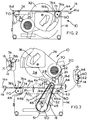
- a power tool 10 is a saw and has legs 12 supporting a frame 14.
- a table 16 is pivoted with respect to the frame through a pivot system 18 described further below.
- the saw assembly 20 comprises a pivot 22 (see also Figure 3) between a pivot member 24 and a saw housing 26.
- a spring 28 biases the saw housing 26 to an open position as shown in Figure 3.
- the saw housing 26 includes a motor 30 drivingly connected to a saw blade 32 (see Figure 2) under a lower guard 34.
- a handle 36 is operable to pivot the housing 26 up and down about pivot 22 to plunge the blade 32 into workpieces supported on the side 16a of the table 16.
- a fence 17 is used to position workpieces.
- the table 16 has a slot (not visible) into which the blade can be lowered.
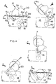
- the housing 26 When pivoted right down against the table 16, the housing 26 can be locked in position by means not shown. When locked in this position, as shown in drawing A of Figure 4, the table 16 is ready for pivoting to the bench saw mode shown in Figure 2. Here, the second side 16b is uppermost and the blade 32 protrudes right through the table 16. This mode is particularly useful for rip cutting of long workpieces moved relative to the blade over, but supported on the table 16.
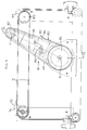
- the pivoting system 18 allowing flip over between the two modes of operation shown in Figures 2 and 3 comprises a first toothed wheel 40 which is fixed to the side 16a of the table through a bracket 42 secured to the table by bolts 44 (see Figure 1). Two such wheels 40 and brackets 42 are provided, at either edge of the table on the side 16a, but only one is shown in the drawings.
- a second wheel 50 is fixed in each side 13 of the frame 14.
- An intermediate member 46 is pivoted about the centre of each wheel 40,50 and serves to tension a belt 48 around the two wheels.
- a cover 52 extends over the wheels 40,50.
- the wheel 40 As the member 46 pivots around the axis 51 of the wheel 50, the wheel 40 is forced to roll inside the belt 48. Since the table 16 is rigidly connected to the wheel 40, the table pivots about pivot axis 41, being the axis of the wheel 40 in the member 46. Moreover the axis moves transversely with respect to itself between two positions indicated at 41a and 41b in the drawings.
- drawing D the saw assembly 20 is beginning to enter the frame 14 and in drawing E it is inside the frame with the table 16 completely inverted (i.e. with side 16b now uppermost).
- axis 41 has moved completely to its second position 41b.
- the second side 16b of the table is at the same level with respect to the frame 14 as the first side 16a was in the snip-off mode of drawing A.
- accessories connectable to the frame 14 can be arranged to be useful to both modes of operation of the saw without having to arrange for any change of height of the table.
- the axis 41 moves in an arc 41c between its two positions 41a, 41b and from either position the axis 41 first moves upwardly so that the table is always raised against gravity from either disposition. This ensures that release of the locks referred to further below does not precipitate movement of the table in an uncontrolled manner which might otherwise constitute a risk.
- a rear knob 60 having a hook 64 is rotatably mounted in the side of the frame 14 on a bolt 62, but it has no function in this position of the saw.
- a stop block 66a is fixed in the side 13 of the frame 14. The intermediate member 46 abuts the block 66a and through the connection of the member 46 to the back of the table 16, supports the table at its read edge 16d.
- Knob 60 is connected to a front knob 70 by a cable 71.
- knob 70 has a handle 72 by means of which it may be turned. Otherwise it is structurally the same as knob 60 and is rotably mounted in the side of the frame 14. It has a hook 74 which catches a catch ledge 76 on the table 16 and which has catch surfaces 76a and b. In the snip-off mode, it is catch 76a which is captured by the hook 74. Rotation of the handle 72 releases hook 74 from the catch.
- the front of the table is supported by the ledge 76 resting on the knob 70. Only one catch is necessary to hold the table 16 down, because the rear edge 16d, for example, cannot rise without the front edge 16c rising. In other words, since the front edge 16c is locked by hook 74, then the whole table is locked as well. In any event, the table is heavy at its rear edge with its burden of the saw assembly 20, and so it is unlikely to lift anyway.
- both knobs 60,70 are spring biased in an anti-clockwise direction (looking at Figure 3) although only knob 60 absolutely requires it given the cable 71 arrangement shown.
- Figures 1 and 3 show the intermediate member 46 to one side of the wheels 40,50 an alternative arrangement is shown in Figures 5 and 6.
- the wheels 40,50 are each constructed from two half-shells 40 a,b and 50a,b, with the member 46 disposed between the half-shells. This has the effect of reducing bending loads on the member 46, because it is supported by the wheels, at least at its most vulnerable areas near its pivots 41,51 to the wheels 40,50 respectively.
- Figure 5 also shows an adjustment mechanism 80 to tension the belt 48 which comprises a tensioner 82 having a curved surface 84 pressing the belt 48 and being connected to the member 46 by bolt and nut 86.
- the bolt passes through an eye 88 of the tensioner enabling its adjustment.
Landscapes
- Engineering & Computer Science (AREA)
- Mechanical Engineering (AREA)
- Life Sciences & Earth Sciences (AREA)
- Wood Science & Technology (AREA)
- Forests & Forestry (AREA)
- Workshop Equipment, Work Benches, Supports, Or Storage Means (AREA)
- Sawing (AREA)
- Machine Tool Units (AREA)
- Finish Polishing, Edge Sharpening, And Grinding By Specific Grinding Devices (AREA)
- Passenger Equipment (AREA)
- Electrical Discharge Machining, Electrochemical Machining, And Combined Machining (AREA)
- Gripping On Spindles (AREA)
- Surgical Instruments (AREA)
- Drilling Tools (AREA)
Applications Claiming Priority (2)
| Application Number | Priority Date | Filing Date | Title |
|---|---|---|---|
| GB9218363 | 1992-08-28 | ||
| GB929218363A GB9218363D0 (en) | 1992-08-28 | 1992-08-28 | Pivoting power tool with table |
Publications (3)
| Publication Number | Publication Date |
|---|---|
| EP0586172A2 true EP0586172A2 (de) | 1994-03-09 |
| EP0586172A3 EP0586172A3 (de) | 1994-03-16 |
| EP0586172B1 EP0586172B1 (de) | 1996-02-07 |
Family
ID=10721135
Family Applications (1)
| Application Number | Title | Priority Date | Filing Date |
|---|---|---|---|
| EP93306680A Expired - Lifetime EP0586172B1 (de) | 1992-08-28 | 1993-08-23 | Motorisiertes schwenkbares Werkzeug mit Tisch |
Country Status (13)
| Country | Link |
|---|---|
| US (1) | US5437319A (de) |
| EP (1) | EP0586172B1 (de) |
| JP (1) | JPH06155154A (de) |
| KR (1) | KR940003666A (de) |
| CN (1) | CN1083423A (de) |
| AT (1) | ATE133893T1 (de) |
| AU (1) | AU660840B2 (de) |
| BR (1) | BR9303133A (de) |
| CA (1) | CA2104186C (de) |
| DE (1) | DE69301513T2 (de) |
| GB (1) | GB9218363D0 (de) |
| PL (1) | PL300190A1 (de) |
| TW (1) | TW256802B (de) |
Cited By (5)
| Publication number | Priority date | Publication date | Assignee | Title |
|---|---|---|---|---|
| EP0780181A1 (de) | 1995-12-22 | 1997-06-25 | Black & Decker Inc. | Kappsägeschlitten |
| EP0780194A1 (de) | 1995-12-22 | 1997-06-25 | Black & Decker Inc. | Kappsägevorrichtung |
| EP1614511A1 (de) * | 2004-07-07 | 2006-01-11 | BLACK & DECKER INC. | Schutzabdeckung für eine Säge |
| EP1623802A1 (de) * | 2004-08-04 | 2006-02-08 | Makita Corporation | Eine zwischen einer Übertisch- und einer Untertischlage verschwenkbare Säge |
| EP1623800A1 (de) * | 2004-07-07 | 2006-02-08 | BLACK & DECKER INC. | Tischverriegelungsvorrichtung für Sägen |
Families Citing this family (42)
| Publication number | Priority date | Publication date | Assignee | Title |
|---|---|---|---|---|
| GB9316723D0 (en) * | 1993-08-12 | 1993-09-29 | Black & Decker Inc | A bevel saw angle indicator |
| US5863052A (en) * | 1994-10-27 | 1999-01-26 | Roman; Gregory S. | Collapsible carpentry work station and push cart combination |
| US6196534B1 (en) * | 1996-08-07 | 2001-03-06 | Black & Decker Inc. | Work bench including a vise |
| USD428426S (en) * | 1999-04-13 | 2000-07-18 | Ryobi North America, Inc. | Miter saw |
| USD423526S (en) * | 1999-04-13 | 2000-04-25 | Ryobi North America, Inc. | Miter saw |
| US6632429B1 (en) * | 1999-12-17 | 2003-10-14 | Joan M. Fallon | Methods for treating pervasive development disorders |
| US6360797B1 (en) * | 1999-12-28 | 2002-03-26 | One World Technologies, Inc. | Power tool and portable support assembly |
| US6687972B1 (en) | 2000-02-18 | 2004-02-10 | Mk Diamond Products, Inc. | Method of forming a portable cutting apparatus |
| US20070053895A1 (en) * | 2000-08-14 | 2007-03-08 | Fallon Joan M | Method of treating and diagnosing parkinsons disease and related dysautonomic disorders |
| US20020157512A1 (en) * | 2000-09-11 | 2002-10-31 | Fasske Wayne C. | Portable apparatus for shearing multi-walled workpieces |
| US8030002B2 (en) | 2000-11-16 | 2011-10-04 | Curemark Llc | Methods for diagnosing pervasive development disorders, dysautonomia and other neurological conditions |
| WO2002076683A1 (en) * | 2001-03-23 | 2002-10-03 | Shear, Llc | A portable apparatus for shearing multi-walled workpieces |
| US9027450B1 (en) | 2003-01-21 | 2015-05-12 | Roland Santa Ana | Work piece cutting apparatus |
| US6942229B2 (en) * | 2003-10-31 | 2005-09-13 | One World Technologies Limited | Collapsible stand for a bench-top power tool |
| US20050211235A1 (en) * | 2004-03-29 | 2005-09-29 | Governo Anthony J | Portable cutting appartus |
| JP2006044066A (ja) * | 2004-08-04 | 2006-02-16 | Makita Corp | フリップオーバーソー |
| JP2006044067A (ja) * | 2004-08-04 | 2006-02-16 | Makita Corp | フリップオーバーソー |
| TWI341781B (en) * | 2004-09-03 | 2011-05-11 | Black & Decker Inc | Trunnion assembly for saws |
| US20080058282A1 (en) | 2005-08-30 | 2008-03-06 | Fallon Joan M | Use of lactulose in the treatment of autism |
| GB0524383D0 (en) * | 2005-11-30 | 2006-01-04 | Sparrow Paul A | Vehicle or static sited modular foldaway quick-release powertool workbenches |
| US20070266835A1 (en) * | 2006-05-17 | 2007-11-22 | Wilson Kelce S | Reconfigurable saw table |
| US7752951B2 (en) * | 2006-09-18 | 2010-07-13 | Normand Ouellette | Convertible circular saw apparatus usable as either a miter saw or a table saw |
| USD574401S1 (en) * | 2006-12-21 | 2008-08-05 | Black & Decker Inc. | Miter saw |
| US8061395B1 (en) * | 2007-10-22 | 2011-11-22 | Atkinson Dennis W | Trailer drop-in work module |
| US8658163B2 (en) * | 2008-03-13 | 2014-02-25 | Curemark Llc | Compositions and use thereof for treating symptoms of preeclampsia |
| US8084025B2 (en) | 2008-04-18 | 2011-12-27 | Curemark Llc | Method for the treatment of the symptoms of drug and alcohol addiction |
| US9320780B2 (en) | 2008-06-26 | 2016-04-26 | Curemark Llc | Methods and compositions for the treatment of symptoms of Williams Syndrome |
| PL2318035T3 (pl) | 2008-07-01 | 2019-10-31 | Curemark Llc | Sposoby i kompozycje do leczenia objawów zaburzeń neurologicznych i zaburzeń zdrowia psychicznego |
| US10776453B2 (en) * | 2008-08-04 | 2020-09-15 | Galenagen, Llc | Systems and methods employing remote data gathering and monitoring for diagnosing, staging, and treatment of Parkinsons disease, movement and neurological disorders, and chronic pain |
| US20100092447A1 (en) | 2008-10-03 | 2010-04-15 | Fallon Joan M | Methods and compositions for the treatment of symptoms of prion diseases |
| CN102300989B (zh) | 2009-01-06 | 2015-12-09 | 柯尔朗恩有限责任公司 | 用于治疗或预防金黄色葡萄球菌感染以及用于根除或减少表面上金黄色葡萄球菌的组合物和方法 |
| KR20170005191A (ko) | 2009-01-06 | 2017-01-11 | 큐어론 엘엘씨 | 이. 콜라이에 의한 구강 감염의 치료 또는 예방을 위한 조성물 및 방법 |
| US9056050B2 (en) | 2009-04-13 | 2015-06-16 | Curemark Llc | Enzyme delivery systems and methods of preparation and use |
| US9511125B2 (en) | 2009-10-21 | 2016-12-06 | Curemark Llc | Methods and compositions for the treatment of influenza |
| US8980252B2 (en) | 2011-04-21 | 2015-03-17 | Curemark Llc | Methods of treatment of schizophrenia |
| US9403224B1 (en) * | 2011-06-30 | 2016-08-02 | Carlos Silva | Combined chop saw and work table and associated use thereof |
| US10350278B2 (en) | 2012-05-30 | 2019-07-16 | Curemark, Llc | Methods of treating Celiac disease |
| CN203141594U (zh) * | 2013-01-29 | 2013-08-21 | 何财柏 | 两用电锯 |
| AU2018250823A1 (en) | 2017-04-10 | 2019-10-17 | Curemark, Llc | Compositions for treating addiction |
| CN107931708A (zh) * | 2017-10-16 | 2018-04-20 | 安徽工程大学 | 一种金属复合材料制备专用切割装置 |
| CN109605493A (zh) * | 2018-11-09 | 2019-04-12 | 林格浪 | 一种便捷式木板切割装置 |
| US11541009B2 (en) | 2020-09-10 | 2023-01-03 | Curemark, Llc | Methods of prophylaxis of coronavirus infection and treatment of coronaviruses |
Family Cites Families (10)
| Publication number | Priority date | Publication date | Assignee | Title |
|---|---|---|---|---|
| US2577206A (en) * | 1948-04-14 | 1951-12-04 | Cleo D Gist | Woodworking machine with a swingably adjustable tool spindle |
| US2744550A (en) * | 1952-02-12 | 1956-05-08 | Reamstown Products Company | Multiple position woodworking machine |
| DE1117359B (de) * | 1958-04-16 | 1961-11-16 | Hans Deckel Dr Ing | Aufspanntisch |
| US3011533A (en) * | 1959-01-14 | 1961-12-05 | Double A Products Company | Combination power tool with adjustable tool spindle |
| US3229732A (en) * | 1963-02-25 | 1966-01-18 | Clary Corp | Wood component member cutting apparatus |
| US3570564A (en) * | 1968-01-03 | 1971-03-16 | Lutz Kg Maschf Eugen | Convertible circular bench saw and mitering saw |
| US4465114A (en) * | 1982-08-27 | 1984-08-14 | Schumacher Robert C | Woodworking bench |
| ES8605410A1 (es) * | 1985-02-13 | 1986-03-16 | Silos Ordonez Alberto | Maquina de uso multiple para trabajar la madera |
| DE3606524C1 (de) * | 1986-02-28 | 1987-04-16 | Lutz Eugen Gmbh & Co | Rasteinrichtung fuer eine Tisch- und Gehrungssaege |
| DE4019222C2 (de) * | 1990-06-15 | 1996-06-13 | Elektra Beckum Ag | Sägeeinrichtung mit einer um 180 Grad wendbar gelagerten Grundplatte |
-
1992
- 1992-08-28 GB GB929218363A patent/GB9218363D0/en active Pending
-
1993
- 1993-08-16 CA CA002104186A patent/CA2104186C/en not_active Expired - Fee Related
- 1993-08-17 TW TW082106605A patent/TW256802B/zh active
- 1993-08-23 EP EP93306680A patent/EP0586172B1/de not_active Expired - Lifetime
- 1993-08-23 AT AT93306680T patent/ATE133893T1/de not_active IP Right Cessation
- 1993-08-23 DE DE69301513T patent/DE69301513T2/de not_active Expired - Lifetime
- 1993-08-25 PL PL93300190A patent/PL300190A1/xx unknown
- 1993-08-25 US US08/111,700 patent/US5437319A/en not_active Expired - Lifetime
- 1993-08-27 KR KR1019930016853A patent/KR940003666A/ko not_active Withdrawn
- 1993-08-27 AU AU44915/93A patent/AU660840B2/en not_active Ceased
- 1993-08-27 BR BR9303133A patent/BR9303133A/pt unknown
- 1993-08-28 CN CN93116581A patent/CN1083423A/zh active Pending
- 1993-08-30 JP JP5214458A patent/JPH06155154A/ja not_active Withdrawn
Cited By (11)
| Publication number | Priority date | Publication date | Assignee | Title |
|---|---|---|---|---|
| EP0780181A1 (de) | 1995-12-22 | 1997-06-25 | Black & Decker Inc. | Kappsägeschlitten |
| EP0780194A1 (de) | 1995-12-22 | 1997-06-25 | Black & Decker Inc. | Kappsägevorrichtung |
| US5896798A (en) * | 1995-12-22 | 1999-04-27 | Garuglieri; Andrea | Chop/slide saw |
| EP1614511A1 (de) * | 2004-07-07 | 2006-01-11 | BLACK & DECKER INC. | Schutzabdeckung für eine Säge |
| EP1623800A1 (de) * | 2004-07-07 | 2006-02-08 | BLACK & DECKER INC. | Tischverriegelungsvorrichtung für Sägen |
| CN100439021C (zh) * | 2004-07-07 | 2008-12-03 | 布莱克和戴克公司 | 电动工具 |
| CN100553837C (zh) * | 2004-07-07 | 2009-10-28 | 布莱克和戴克公司 | 电动工具 |
| AU2005202832B2 (en) * | 2004-07-07 | 2010-05-13 | Black & Decker, Inc. | Table latch assembly for saws |
| AU2005202871B2 (en) * | 2004-07-07 | 2010-05-27 | Black & Decker, Inc. | Blade guard assembly for saws |
| EP1623802A1 (de) * | 2004-08-04 | 2006-02-08 | Makita Corporation | Eine zwischen einer Übertisch- und einer Untertischlage verschwenkbare Säge |
| DE202005021523U1 (de) | 2004-08-04 | 2008-06-12 | Makita Corp., Anjo | Schwenkbare Tischsäge |
Also Published As
| Publication number | Publication date |
|---|---|
| JPH06155154A (ja) | 1994-06-03 |
| TW256802B (de) | 1995-09-11 |
| GB9218363D0 (en) | 1992-10-14 |
| CA2104186C (en) | 2005-11-01 |
| US5437319A (en) | 1995-08-01 |
| AU4491593A (en) | 1994-03-03 |
| EP0586172B1 (de) | 1996-02-07 |
| EP0586172A3 (de) | 1994-03-16 |
| CA2104186A1 (en) | 1994-03-01 |
| DE69301513D1 (de) | 1996-03-21 |
| BR9303133A (pt) | 1994-03-22 |
| PL300190A1 (en) | 1994-03-07 |
| KR940003666A (ko) | 1994-03-12 |
| DE69301513T2 (de) | 1996-09-19 |
| AU660840B2 (en) | 1995-07-06 |
| ATE133893T1 (de) | 1996-02-15 |
| CN1083423A (zh) | 1994-03-09 |
Similar Documents
| Publication | Publication Date | Title |
|---|---|---|
| EP0586172B1 (de) | Motorisiertes schwenkbares Werkzeug mit Tisch | |
| US4962685A (en) | Production table saw | |
| EP0586174B1 (de) | Schwenkbarer Tisch mit Motorwerkzeug | |
| US5317944A (en) | Adjustable protecting guard apparatus for a blade of a table saw | |
| US5347902A (en) | Motorized miter box | |
| EP2593279B1 (de) | Tragbare tischsäge | |
| US5042348A (en) | Compound miter saw | |
| JPH0711921Y2 (ja) | 作業台の刃物位置設定装置 | |
| CA2036664C (en) | Portable circular saw | |
| US4276799A (en) | Power tool apparatus | |
| EP0023344B1 (de) | Höheneinstellmechanismus für eine Tischsäge u. dgl. | |
| CA1221296A (en) | Tool elevation and bevel adjustment for direct drive power tool | |
| CA2713686C (en) | Power tool cutting apparatus | |
| EP1577066B1 (de) | Schneidblatt- und Motorträger mit Höhe/Winkel-Einstellvorrichtung | |
| US5189937A (en) | Circular saw arrangement | |
| US3139124A (en) | Swingable mount for power saws | |
| US7600456B2 (en) | Modular guard system for a power saw | |
| US8245614B2 (en) | Guard assembly for table saw | |
| US4549455A (en) | Combination table saw | |
| US9027450B1 (en) | Work piece cutting apparatus | |
| US5896798A (en) | Chop/slide saw | |
| US3952622A (en) | Vice mounted multiple-use band saw with detachable work surface | |
| US3452629A (en) | Tilting band saw | |
| US4154144A (en) | Milling machine power feed | |
| AU701082B2 (en) | A workbench and various components therefor |
Legal Events
| Date | Code | Title | Description |
|---|---|---|---|
| PUAI | Public reference made under article 153(3) epc to a published international application that has entered the european phase |
Free format text: ORIGINAL CODE: 0009012 |
|
| PUAL | Search report despatched |
Free format text: ORIGINAL CODE: 0009013 |
|
| AK | Designated contracting states |
Kind code of ref document: A2 Designated state(s): AT CH DE ES FR GB IT LI NL SE |
|
| AK | Designated contracting states |
Kind code of ref document: A3 Designated state(s): AT CH DE ES FR GB IT LI NL SE |
|
| 17P | Request for examination filed |
Effective date: 19940429 |
|
| 17Q | First examination report despatched |
Effective date: 19950427 |
|
| GRAA | (expected) grant |
Free format text: ORIGINAL CODE: 0009210 |
|
| AK | Designated contracting states |
Kind code of ref document: B1 Designated state(s): AT CH DE ES FR GB IT LI NL SE |
|
| PG25 | Lapsed in a contracting state [announced via postgrant information from national office to epo] |
Ref country code: ES Free format text: THE PATENT HAS BEEN ANNULLED BY A DECISION OF A NATIONAL AUTHORITY Effective date: 19960207 Ref country code: AT Effective date: 19960207 |
|
| REF | Corresponds to: |
Ref document number: 133893 Country of ref document: AT Date of ref document: 19960215 Kind code of ref document: T |
|
| REF | Corresponds to: |
Ref document number: 69301513 Country of ref document: DE Date of ref document: 19960321 |
|
| REG | Reference to a national code |
Ref country code: CH Ref legal event code: NV Representative=s name: PATENTANWALTSBUREAU R. A. MASPOLI |
|
| ITF | It: translation for a ep patent filed | ||
| PG25 | Lapsed in a contracting state [announced via postgrant information from national office to epo] |
Ref country code: SE Effective date: 19960507 |
|
| ET | Fr: translation filed | ||
| PLBE | No opposition filed within time limit |
Free format text: ORIGINAL CODE: 0009261 |
|
| STAA | Information on the status of an ep patent application or granted ep patent |
Free format text: STATUS: NO OPPOSITION FILED WITHIN TIME LIMIT |
|
| 26N | No opposition filed | ||
| REG | Reference to a national code |
Ref country code: GB Ref legal event code: IF02 |
|
| PGFP | Annual fee paid to national office [announced via postgrant information from national office to epo] |
Ref country code: NL Payment date: 20060824 Year of fee payment: 14 |
|
| PG25 | Lapsed in a contracting state [announced via postgrant information from national office to epo] |
Ref country code: NL Free format text: LAPSE BECAUSE OF NON-PAYMENT OF DUE FEES Effective date: 20080301 |
|
| NLV4 | Nl: lapsed or anulled due to non-payment of the annual fee |
Effective date: 20080301 |
|
| PGFP | Annual fee paid to national office [announced via postgrant information from national office to epo] |
Ref country code: CH Payment date: 20080825 Year of fee payment: 16 |
|
| PGFP | Annual fee paid to national office [announced via postgrant information from national office to epo] |
Ref country code: IT Payment date: 20080828 Year of fee payment: 16 Ref country code: FR Payment date: 20080818 Year of fee payment: 16 |
|
| PGFP | Annual fee paid to national office [announced via postgrant information from national office to epo] |
Ref country code: GB Payment date: 20080827 Year of fee payment: 16 |
|
| REG | Reference to a national code |
Ref country code: CH Ref legal event code: PL |
|
| GBPC | Gb: european patent ceased through non-payment of renewal fee |
Effective date: 20090823 |
|
| PG25 | Lapsed in a contracting state [announced via postgrant information from national office to epo] |
Ref country code: LI Free format text: LAPSE BECAUSE OF NON-PAYMENT OF DUE FEES Effective date: 20090831 Ref country code: CH Free format text: LAPSE BECAUSE OF NON-PAYMENT OF DUE FEES Effective date: 20090831 |
|
| REG | Reference to a national code |
Ref country code: FR Ref legal event code: ST Effective date: 20100430 |
|
| PG25 | Lapsed in a contracting state [announced via postgrant information from national office to epo] |
Ref country code: FR Free format text: LAPSE BECAUSE OF NON-PAYMENT OF DUE FEES Effective date: 20090831 |
|
| PG25 | Lapsed in a contracting state [announced via postgrant information from national office to epo] |
Ref country code: GB Free format text: LAPSE BECAUSE OF NON-PAYMENT OF DUE FEES Effective date: 20090823 |
|
| PG25 | Lapsed in a contracting state [announced via postgrant information from national office to epo] |
Ref country code: IT Free format text: LAPSE BECAUSE OF NON-PAYMENT OF DUE FEES Effective date: 20090823 |
|
| PGFP | Annual fee paid to national office [announced via postgrant information from national office to epo] |
Ref country code: DE Payment date: 20110830 Year of fee payment: 19 |
|
| PG25 | Lapsed in a contracting state [announced via postgrant information from national office to epo] |
Ref country code: DE Free format text: LAPSE BECAUSE OF NON-PAYMENT OF DUE FEES Effective date: 20130301 |
|
| REG | Reference to a national code |
Ref country code: DE Ref legal event code: R119 Ref document number: 69301513 Country of ref document: DE Effective date: 20130301 |