EP0586325A2 - Verfahren und Gerät zum TIG-Schweissen - Google Patents
Verfahren und Gerät zum TIG-Schweissen Download PDFInfo
- Publication number
- EP0586325A2 EP0586325A2 EP93610045A EP93610045A EP0586325A2 EP 0586325 A2 EP0586325 A2 EP 0586325A2 EP 93610045 A EP93610045 A EP 93610045A EP 93610045 A EP93610045 A EP 93610045A EP 0586325 A2 EP0586325 A2 EP 0586325A2
- Authority
- EP
- European Patent Office
- Prior art keywords
- welding
- arc
- positive
- period
- positive period
- Prior art date
- Legal status (The legal status is an assumption and is not a legal conclusion. Google has not performed a legal analysis and makes no representation as to the accuracy of the status listed.)
- Granted
Links
Images


Classifications
-
- B—PERFORMING OPERATIONS; TRANSPORTING
- B23—MACHINE TOOLS; METAL-WORKING NOT OTHERWISE PROVIDED FOR
- B23K—SOLDERING OR UNSOLDERING; WELDING; CLADDING OR PLATING BY SOLDERING OR WELDING; CUTTING BY APPLYING HEAT LOCALLY, e.g. FLAME CUTTING; WORKING BY LASER BEAM
- B23K9/00—Arc welding or cutting
- B23K9/09—Arrangements or circuits for arc welding with pulsed current or voltage
- B23K9/091—Arrangements or circuits for arc welding with pulsed current or voltage characterised by the circuits
-
- B—PERFORMING OPERATIONS; TRANSPORTING
- B23—MACHINE TOOLS; METAL-WORKING NOT OTHERWISE PROVIDED FOR
- B23K—SOLDERING OR UNSOLDERING; WELDING; CLADDING OR PLATING BY SOLDERING OR WELDING; CUTTING BY APPLYING HEAT LOCALLY, e.g. FLAME CUTTING; WORKING BY LASER BEAM
- B23K9/00—Arc welding or cutting
- B23K9/06—Arrangements or circuits for starting the arc, e.g. by generating ignition voltage, or for stabilising the arc
- B23K9/073—Stabilising the arc
- B23K9/0738—Stabilising of the arc by automatic re-ignition means
Definitions
- the invention relates to a method for TIG welding of the kind disclosed in the preamble to claim 1.
- TIG arc welding with alternating current is used to a great extent for the welding of metals such as aluminium and aluminium alloys.
- the polarity of current and voltage changes traditionally with 50 or 60 Hz synchronously with the frequency of the power supply to which the welding equipment is connected.
- the positive half cycle i.e. when the welding electrode voltage is positive in relation to the workpiece, for cleaning the workpiece by removing the aluminium-oxide layer on the surface of the workpiece, and the negative half cycle is used to heat the workpiece so that a "weldpool" is formed.
- the positive half cycle approx. 1/3 of the power is dissipated in the workpiece and approx. 2/3 of the power is dissipated in the tunsten electrode.
- the negative half cycle approx. 2/3 of the power is dissipated in the workpiece and approx. 1/3 of the power is dissipated in the tungsten electrode.
- the arc When the polarity is changed, the arc must be re-ignited. This occurs easily when the change is from positive to negative polarity, in that the electrode is hot and easily emits electrons, whereas it is difficult to change from the negative polarity to positive polarity. This is partly due to the fact that the electrode is hotter than the weldpool, but also because pure aluminium does not easily emit electrons.
- the energy required for the emission of electrons from aluminium is very high, and since aluminium oxide is electrically insulating, such a current source must necessarily be equipped with a circuit which imparts a brief pulse with high voltage to the welding circuit in order to re-establish the positive half cycle.
- the object of the invention is therefore to present a welding method and welding apparatus with which it is possible to achieve optimum welding quality, which is of very great practical significance.
- the welding current source is arranged in such a manner that the polarity of the welding current is controlled from a control unit by means of one or more signals, so that it is possible to regulate the frequency of the AC balance, i.e. the relationship between the time for which the polarity of the tungten electrode is positive and the time for which it is negative.
- the control circuit according to the invention will thus not be operative.
- the period is shortened in that an immediate shift to the negative polarity takes place. The principle is thus that if an arc can not be established during the positive period, this is because there is no need for cleaning and thus there is no reason to wait before changing to negative polarity.
- the stabilizing effect and the herewith increased welding quality is achieved by ensuring a more constant supply of energy to the arc than is the case with the known welding processes.
- Claims 2-5 disclose advantageous methods of TIG welding with which the improved arc stability and optimum welding quality can be achieved.
- the invention also relates to a TIG welding machine as disclosed and characterized in claim 6 or 9.
- TIG welding machine as disclosed and characterized in claim 6 or 9.
- Claims 7, 8 and 10 disclose advantageous embodiments for the welding machine's electronic control circuit.
- FIG. 1 Uppermost in fig. 1 is shown the welding voltage as a function of the time, and lowermost the welding current as a function of the time, and as they appear in a known welding machine without use of the method according to the invention.
- the figure shows six voltage periods numbered 1-6 with corresponding current periods. In order to achieve ignition in the positive periods, each period starts with an ignition voltage pulse 7 which is higher than both the welding voltage and the no-load voltage of the welding current source.
- ignition voltage pulse 7 which is higher than both the welding voltage and the no-load voltage of the welding current source.
- Such means for the re-ignition of the arc in the positive periods are known, and therefore they will not be dealt with in more detail. It will be seen in the first three periods that correct re-ignition occurs both in the positive part and in the negative part of each period. The welding voltage and welding current are therefore completely normal and as desired.
- Fig. 2 shows welding voltage and welding current as a function of the time when use is made of the method according to the invention, e.g. during the use of one of the welding current sources described later.
- Fig. 2 shows the same six periods as in fig. 1, and it will be seen that no re-ignition occurs in the positive parts of the 4th and 5th periods, and for this reason the positive period is shortened so that the time for which the current is 0 is shortened.
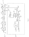
- the reference number 10 indicates an inverter-based welding machine of a known type which functions in accordance with the method which was described in connection with fig. 1.
- the welding machine or the welding current source 10 receives normal 3-phased alternating current 11 from a mains supply, and the power is fed to an AC/DC converter 12, normally a 3-phase rectifier. From here, the DC output power is fed to a DC/AC converter 13, the output voltage of which is shown as square-wave pulses, e.g. with a frequency in the order of 50 kHz.
- the output power is fed to a transformer 14 and further to an AC/DC converter 15. In this manner, a desired DC voltage level is achieved by using a transformer 14 of minimum size, and thus the usually very large and heavy welding transformers are avoided.
- the DC power is then fed to a DC/AC converter 16 which is configured as a controllable inverter coupling, the output frequency of which can be regulated, e.g. from 5 Hz to 500 Hz.
- the electronic control circuits and measuring circuits in the converters are normally arranged in such a way that the strength of the current and the frequency are constantly monitored, and thus the circuits can instantly register if there is no flow of welding current in the welding circuit 17 between the output 17'and 17'', where for example the output 17' is the tungsten electrode in the TIG welding arrangement and 17'' is the electrical conductor which leads to the workpiece.
- the welding current source is normally provided with means of regulation, whereby it is possible to adjust the relationship between the time for which the polarity of the tungsten electrode is positive and the time for which the polarity is negative, so that the welding machine operator himself can adjust the cleaning effect.
- a circuit 20 is added which, via the lead 21, senses whether or not a re-ignition has occurred in the positive period. If a re-ignition has occurred, the control circuit 20 does not have any influence on the welding process. On the other hand, if re-ignition has not occurred, the control circuit 20 will react and will transmit a signal via the lead 22. This signal will instantly ensure that the welding voltage changes from positive to negative potential, cf. the explanation in connection with fig. 2
- the control circuit 20 comprises an oscillator 29 with frequency adjustment elements 30, so that an adjustable saw-tooth voltage is fed to the comparator 28, to which there is also fed a balance signal from a balance regulation element 31. There is hereby generated the control voltage which ensures the welding voltage changes in the controllable inverter 16.
- the output signal from the comparator 28 is fed to a logical circuit 25, which forms part of a latch coupling 24, and also to a logical circuit 32.
- the lead 21 is connected via a comparator 23 to the other input of the latch coupling 24.
- the comparator 23 is coupled to a reference voltage which can be adjustable.
- the control circuit 20 functions as follows: When a signal is received at the latch coupling 24 via the lead 21 and the comparator 23, this indicates that no reignition has occurred in the positive period, and the logical circuit 32 immediately switches over so that a changeover of the welding voltage takes place via the lead 22. If there is no signal from the comparator 23, the latch coupling 24 is not triggered and the control signal from the comparator 28 passes via the lead 33 directly to the logical circuit 32. Consequently, there is no changeover of the welding voltage from positive to negative polarity until the welding current sequence has been as long as determined by the adjusting elements 30, 31.
- a programmable microprocessor is inserted in the welding machine 10, which is suitably programmed in an appropriate programming language so that the logical function diagram in fig. 4 is followed.
- Fig. 5 shows chronologically the changeover of the welding voltage, in that t pos indicates the period of time for which the voltage is positive and t neg indicates the period of time for which the voltage is negative.
- t pos 1 f ⁇ (100 - B) 100
- the electronic switch in the inverter coupling 16 is hereby changed over by means of the microprocesor following the same function as explained in connection with figs. 2 and 3 of the drawing.
- the fully-drawn line in fig. 5 shows the chronological sequence of the welding voltage when the welding takes place in a normal manner, i.e. with total re-ignition both in the positive and the negative periods
- the dotted line in fig. 5 shows the chronological sequence of the welding voltage when no re-ignition occurs in the positive period, and the changeover of the welding voltage takes place in accordance with the logical function diagram in fig. 4 or the control circuit 20 in fig. 3.
Landscapes
- Engineering & Computer Science (AREA)
- Physics & Mathematics (AREA)
- Plasma & Fusion (AREA)
- Mechanical Engineering (AREA)
- Arc Welding In General (AREA)
- Arc Welding Control (AREA)
Applications Claiming Priority (2)
| Application Number | Priority Date | Filing Date | Title |
|---|---|---|---|
| DK1073/92 | 1992-08-28 | ||
| DK107392A DK172238B1 (da) | 1992-08-28 | 1992-08-28 | Fremgangsmåde og apparat til TIG-svejsning |
Publications (3)
| Publication Number | Publication Date |
|---|---|
| EP0586325A2 true EP0586325A2 (de) | 1994-03-09 |
| EP0586325A3 EP0586325A3 (en) | 1994-08-10 |
| EP0586325B1 EP0586325B1 (de) | 1997-06-04 |
Family
ID=8100685
Family Applications (1)
| Application Number | Title | Priority Date | Filing Date |
|---|---|---|---|
| EP93610045A Expired - Lifetime EP0586325B1 (de) | 1992-08-28 | 1993-08-10 | Verfahren und Gerät zum TIG-Schweissen |
Country Status (5)
| Country | Link |
|---|---|
| US (1) | US5365035A (de) |
| EP (1) | EP0586325B1 (de) |
| AT (1) | ATE153891T1 (de) |
| DE (1) | DE69311234T2 (de) |
| DK (1) | DK172238B1 (de) |
Cited By (2)
| Publication number | Priority date | Publication date | Assignee | Title |
|---|---|---|---|---|
| EP2684634A1 (de) * | 2012-07-09 | 2014-01-15 | Cloos Innovations-GmbH | Wechselstrom-Metallschutzgas-Schweißverfahren mit kontinuierlich zugeführtem Schweißdraht |
| CN109551083A (zh) * | 2017-09-26 | 2019-04-02 | 株式会社达谊恒 | 交流非自耗电极电弧焊接控制方法 |
Families Citing this family (7)
| Publication number | Priority date | Publication date | Assignee | Title |
|---|---|---|---|---|
| DK172238B1 (da) * | 1992-08-28 | 1998-02-02 | Migatronic Svejsemask | Fremgangsmåde og apparat til TIG-svejsning |
| DE19720875A1 (de) * | 1997-05-17 | 1998-11-19 | Rehm Gmbh U Co Schweistechnik | Verfahren und Vorrichtung zur Steuerung des Schweißstromes beim WIG-Schweißen |
| US6087628A (en) * | 1997-06-16 | 2000-07-11 | Illinois Tool Works Inc. | Method and apparatus for controlling a welding power supply |
| US5990443A (en) * | 1998-03-12 | 1999-11-23 | Thermal Dynamics Corporation | Plasma torch pilot arc circuit |
| CN102470474B (zh) * | 2010-02-23 | 2015-07-08 | 松下电器产业株式会社 | 交流电弧焊接方法及交流电弧焊接装置 |
| US10052707B2 (en) * | 2014-04-04 | 2018-08-21 | Lincoln Global, Inc. | Method and system to use AC welding waveform and enhanced consumable to improve welding of galvanized workpiece |
| EP3825051A1 (de) | 2019-11-21 | 2021-05-26 | FRONIUS INTERNATIONAL GmbH | Verfahren und vorrichtung zum schweissen mit einer nichtabschmelzenden elektrode |
Family Cites Families (8)
| Publication number | Priority date | Publication date | Assignee | Title |
|---|---|---|---|---|
| US3895212A (en) * | 1972-05-10 | 1975-07-15 | Babcock & Wilcox Co | Fusion welding |
| GB1492311A (en) * | 1975-03-06 | 1977-11-16 | Atomic Energy Authority Uk | Electric arc-welding processes and apparatus therefor |
| US4038515A (en) * | 1975-05-08 | 1977-07-26 | Miller Electric Manufacturing Company | Asymmetrical a.c. welder |
| DE2658724A1 (de) * | 1976-12-24 | 1978-06-29 | Interatom | Stromquelle, insbesondere schweissstromquelle |
| DE3277803D1 (en) * | 1981-10-27 | 1988-01-21 | Fronius Schweissmasch | Electronic welding device |
| US4947021A (en) * | 1987-12-29 | 1990-08-07 | The Lincoln Electric Company | Method and apparatus for TIG welding |
| US4963715A (en) * | 1989-03-27 | 1990-10-16 | Venable Industries, Inc. | Variable polarity power supply for welding |
| DK172238B1 (da) * | 1992-08-28 | 1998-02-02 | Migatronic Svejsemask | Fremgangsmåde og apparat til TIG-svejsning |
-
1992
- 1992-08-28 DK DK107392A patent/DK172238B1/da not_active IP Right Cessation
-
1993
- 1993-08-10 AT AT93610045T patent/ATE153891T1/de not_active IP Right Cessation
- 1993-08-10 DE DE69311234T patent/DE69311234T2/de not_active Expired - Fee Related
- 1993-08-10 EP EP93610045A patent/EP0586325B1/de not_active Expired - Lifetime
- 1993-08-18 US US08/108,998 patent/US5365035A/en not_active Expired - Fee Related
Cited By (2)
| Publication number | Priority date | Publication date | Assignee | Title |
|---|---|---|---|---|
| EP2684634A1 (de) * | 2012-07-09 | 2014-01-15 | Cloos Innovations-GmbH | Wechselstrom-Metallschutzgas-Schweißverfahren mit kontinuierlich zugeführtem Schweißdraht |
| CN109551083A (zh) * | 2017-09-26 | 2019-04-02 | 株式会社达谊恒 | 交流非自耗电极电弧焊接控制方法 |
Also Published As
| Publication number | Publication date |
|---|---|
| US5365035A (en) | 1994-11-15 |
| DK107392A (da) | 1994-03-01 |
| ATE153891T1 (de) | 1997-06-15 |
| DE69311234T2 (de) | 1997-11-13 |
| DK172238B1 (da) | 1998-02-02 |
| EP0586325A3 (en) | 1994-08-10 |
| EP0586325B1 (de) | 1997-06-04 |
| DE69311234D1 (de) | 1997-07-10 |
| DK107392D0 (da) | 1992-08-28 |
Similar Documents
| Publication | Publication Date | Title |
|---|---|---|
| KR100281315B1 (ko) | 용접용 전원장치 및 그 제조방법 | |
| KR840002190B1 (ko) | 펄스아아크 용접장치 | |
| US6034350A (en) | Method and apparatus for initiating a welding arc using a background circuit | |
| US4092517A (en) | Electric arc welding processes and apparatus therefor | |
| EP0669182B1 (de) | Steuerverfahren vom Wiederstandschweissen mit unscharften Logik | |
| EP0947276B1 (de) | Verfahren und Vorrichtung zur Zündung eines Schweisslichtbogens | |
| US20080023457A1 (en) | Method and Apparatus For Pulse and Short Circuit Arc Welding | |
| US5365035A (en) | Method and apparatus for TIG welding | |
| EP0260963A2 (de) | Widerstandsschweissmaschine des Wechselrichtertyps | |
| EP0947278A2 (de) | Widerstandsschweissregeleinrichtung. | |
| US5760372A (en) | Arc welder | |
| RU2293000C2 (ru) | Двухступенчатая установка электродуговой сварки и способ электродуговой сварки (варианты) | |
| JPH03474A (ja) | 消耗電極式アーク溶接用電源の出力制御方法 | |
| JPH0747208B2 (ja) | 消耗電極式アーク溶接機 | |
| JP2854613B2 (ja) | 消耗電極式ガスシールドアーク溶接における交流アーク溶接方法およびその装置 | |
| JPS5886978A (ja) | ア−ク溶接装置 | |
| JP7522933B2 (ja) | アーク放電の点弧時にエネルギーを制限する方法及び装置 | |
| KR960004790B1 (ko) | 단락이행형 아크용접기의 출력제어장치 및 제어방법 | |
| JP3202828B2 (ja) | 消耗電極式ガスシールドアーク溶接の出力制御方法およびその溶接装置 | |
| GB2053762A (en) | Controlling gas-shielded consumable electrode arc welding in dip transfer mode | |
| JP2584140B2 (ja) | 交流tig溶接機 | |
| JP2711137B2 (ja) | 交流ティグ溶接装置 | |
| CN110744173A (zh) | 一种脉冲mig焊接电源 | |
| JPH07136764A (ja) | ホットワイヤtig溶接装置 | |
| JP2545252B2 (ja) | スポット溶接装置のケーブル損傷検出方法 |
Legal Events
| Date | Code | Title | Description |
|---|---|---|---|
| PUAI | Public reference made under article 153(3) epc to a published international application that has entered the european phase |
Free format text: ORIGINAL CODE: 0009012 |
|
| AK | Designated contracting states |
Kind code of ref document: A2 Designated state(s): AT BE CH DE ES FR GB IT LI NL SE |
|
| PUAL | Search report despatched |
Free format text: ORIGINAL CODE: 0009013 |
|
| AK | Designated contracting states |
Kind code of ref document: A3 Designated state(s): AT BE CH DE ES FR GB IT LI NL SE |
|
| 17P | Request for examination filed |
Effective date: 19941203 |
|
| 17Q | First examination report despatched |
Effective date: 19951121 |
|
| GRAG | Despatch of communication of intention to grant |
Free format text: ORIGINAL CODE: EPIDOS AGRA |
|
| GRAH | Despatch of communication of intention to grant a patent |
Free format text: ORIGINAL CODE: EPIDOS IGRA |
|
| GRAH | Despatch of communication of intention to grant a patent |
Free format text: ORIGINAL CODE: EPIDOS IGRA |
|
| GRAA | (expected) grant |
Free format text: ORIGINAL CODE: 0009210 |
|
| AK | Designated contracting states |
Kind code of ref document: B1 Designated state(s): AT BE CH DE ES FR GB IT LI NL SE |
|
| PG25 | Lapsed in a contracting state [announced via postgrant information from national office to epo] |
Ref country code: NL Free format text: LAPSE BECAUSE OF FAILURE TO SUBMIT A TRANSLATION OF THE DESCRIPTION OR TO PAY THE FEE WITHIN THE PRESCRIBED TIME-LIMIT Effective date: 19970604 Ref country code: LI Effective date: 19970604 Ref country code: ES Free format text: THE PATENT HAS BEEN ANNULLED BY A DECISION OF A NATIONAL AUTHORITY Effective date: 19970604 Ref country code: CH Effective date: 19970604 Ref country code: BE Effective date: 19970604 Ref country code: AT Effective date: 19970604 |
|
| REF | Corresponds to: |
Ref document number: 153891 Country of ref document: AT Date of ref document: 19970615 Kind code of ref document: T |
|
| REG | Reference to a national code |
Ref country code: CH Ref legal event code: EP |
|
| REF | Corresponds to: |
Ref document number: 69311234 Country of ref document: DE Date of ref document: 19970710 |
|
| ET | Fr: translation filed | ||
| ITF | It: translation for a ep patent filed | ||
| PG25 | Lapsed in a contracting state [announced via postgrant information from national office to epo] |
Ref country code: SE Effective date: 19970904 |
|
| NLV1 | Nl: lapsed or annulled due to failure to fulfill the requirements of art. 29p and 29m of the patents act | ||
| REG | Reference to a national code |
Ref country code: CH Ref legal event code: PL |
|
| PLBE | No opposition filed within time limit |
Free format text: ORIGINAL CODE: 0009261 |
|
| STAA | Information on the status of an ep patent application or granted ep patent |
Free format text: STATUS: NO OPPOSITION FILED WITHIN TIME LIMIT |
|
| 26N | No opposition filed | ||
| REG | Reference to a national code |
Ref country code: GB Ref legal event code: IF02 |
|
| PGFP | Annual fee paid to national office [announced via postgrant information from national office to epo] |
Ref country code: GB Payment date: 20040728 Year of fee payment: 12 |
|
| PGFP | Annual fee paid to national office [announced via postgrant information from national office to epo] |
Ref country code: FR Payment date: 20040830 Year of fee payment: 12 |
|
| PG25 | Lapsed in a contracting state [announced via postgrant information from national office to epo] |
Ref country code: IT Free format text: LAPSE BECAUSE OF NON-PAYMENT OF DUE FEES Effective date: 20050810 Ref country code: GB Free format text: LAPSE BECAUSE OF NON-PAYMENT OF DUE FEES Effective date: 20050810 |
|
| GBPC | Gb: european patent ceased through non-payment of renewal fee |
Effective date: 20050810 |
|
| PG25 | Lapsed in a contracting state [announced via postgrant information from national office to epo] |
Ref country code: FR Free format text: LAPSE BECAUSE OF NON-PAYMENT OF DUE FEES Effective date: 20060428 |
|
| REG | Reference to a national code |
Ref country code: FR Ref legal event code: ST Effective date: 20060428 |
|
| PGFP | Annual fee paid to national office [announced via postgrant information from national office to epo] |
Ref country code: DE Payment date: 20070927 Year of fee payment: 15 |
|
| PG25 | Lapsed in a contracting state [announced via postgrant information from national office to epo] |
Ref country code: DE Free format text: LAPSE BECAUSE OF NON-PAYMENT OF DUE FEES Effective date: 20090303 |