EP0586728B1 - Zellenradschleuse - Google Patents
Zellenradschleuse Download PDFInfo
- Publication number
- EP0586728B1 EP0586728B1 EP92115382A EP92115382A EP0586728B1 EP 0586728 B1 EP0586728 B1 EP 0586728B1 EP 92115382 A EP92115382 A EP 92115382A EP 92115382 A EP92115382 A EP 92115382A EP 0586728 B1 EP0586728 B1 EP 0586728B1
- Authority
- EP
- European Patent Office
- Prior art keywords
- rotor
- casing
- sleeve
- rotation
- distributor
- Prior art date
- Legal status (The legal status is an assumption and is not a legal conclusion. Google has not performed a legal analysis and makes no representation as to the accuracy of the status listed.)
- Expired - Lifetime
Links
Images

Classifications
-
- B—PERFORMING OPERATIONS; TRANSPORTING
- B65—CONVEYING; PACKING; STORING; HANDLING THIN OR FILAMENTARY MATERIAL
- B65G—TRANSPORT OR STORAGE DEVICES, e.g. CONVEYORS FOR LOADING OR TIPPING, SHOP CONVEYOR SYSTEMS OR PNEUMATIC TUBE CONVEYORS
- B65G53/00—Conveying materials in bulk through troughs, pipes or tubes by floating the materials or by flow of gas, liquid or foam
- B65G53/34—Details
- B65G53/40—Feeding or discharging devices
- B65G53/46—Gates or sluices, e.g. rotary wheels
-
- B—PERFORMING OPERATIONS; TRANSPORTING
- B65—CONVEYING; PACKING; STORING; HANDLING THIN OR FILAMENTARY MATERIAL
- B65G—TRANSPORT OR STORAGE DEVICES, e.g. CONVEYORS FOR LOADING OR TIPPING, SHOP CONVEYOR SYSTEMS OR PNEUMATIC TUBE CONVEYORS
- B65G53/00—Conveying materials in bulk through troughs, pipes or tubes by floating the materials or by flow of gas, liquid or foam
- B65G53/34—Details
- B65G53/40—Feeding or discharging devices
- B65G53/46—Gates or sluices, e.g. rotary wheels
- B65G53/4608—Turnable elements, e.g. rotary wheels with pockets or passages for material
- B65G53/4625—Turnable elements, e.g. rotary wheels with pockets or passages for material with axis of turning perpendicular to flow
- B65G53/4633—Turnable elements, e.g. rotary wheels with pockets or passages for material with axis of turning perpendicular to flow the element having pockets, rotated from charging position to discharging position, i.e. discrete flow
Definitions
- the present invention relates to a device for feeding or discharging, in particular continuously, powdery products, and more particularly relates to a rotary distributor having an improved seal.
- Patent FR 2,012,300 describes a chute distributor for feeding and unloading finely divided products into a tank.
- the rotary distributor described comprises a rotor formed with at least one cell and supported by rotation means, such as journals, mounted on a casing provided with tubular sleeves for supplying and discharging the product, each cell being arranged so as to be in communication, while the rotor is rotating, with said supply and unloading sleeves.
- the interior of the dispenser is sealed against the external atmosphere by means of fixed supply and unloading sleeves, as well as by at least one cable gland.
- An object of the present invention is the production of a rotary distributor, by implementing a new sealing principle which makes it possible to facilitate and improve the sealing of said distributor to the external atmosphere.
- the rotary distributor comprises two sealing elements each consisting of an annular wear ring, the face of which bears against the supply or discharge sleeve is flat, and the face of which is in friction permanent on the rotor is semi-cylindrical in the direction of the axis of rotation of the rotor.
- An advantage of the dispenser according to the present invention is to ensure a perfect seal with the outside and therefore to allow constant isolation of the pulverulent products from the outside atmosphere, this from their introduction into the reservoir until their unloading. Another advantage is to allow the introduction and unloading of the pulverulent products without significant differential pressure (3-10 bars), in installations working under a pressure of 6-7 bars or under a vapor pressure at high temperature, of the 'order of 200 ° C, this with a very low leakage rate. Another advantage is that the dispenser is easily removable, which can facilitate its maintenance. Another advantage is the possibility of adjusting the friction force of each of the sealing elements on the rotor as a function of the operating pressure.
- the rotary distributor according to the present invention is more particularly usable in the context of food applications, for example applicable to granules or pulverulent products.
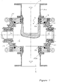
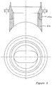
- the rotary distributor represented in FIGS. 1 and 2 comprises a cylindrical rotor 1 which comprises at least one cell 2.
- the rotor can comprise one to three cells and can rotate, preferably, at a slow speed of the order of 5- 100 revolutions / minute.
- the rotor is disposed in a casing 3 which receives two end flanges 10 and 11. These flanges are coupled to means for guiding in rotation 16, which may consist of bearings, or rings, self-lubricating.
- the cylindrical rotor 1 is mounted inside the casing 3 and is guided in rotation relative to said casing by said self-lubricating bearings.
- the rotation of the rotor relative to the housing can be complete or only partial, for example pendulum. The rotation can be ensured by a motor, not shown in the figures.
- These two sleeves are therefore mobile and their position can be adjusted and fixed.
- the two sealing elements 6a and 6b are mounted in permanent friction on the rotor. Their longitudinal axes are perpendicular to the axis of rotation of the rotor, and the force of their friction on the rotor can be adjusted using adjustment means 8,9, such as a screw and a compression spring.
- the casing can be made of stainless steel, for example of the Z 2 CN 18-10 type, stabilized in temperature.
- the two end flanges can be made of stainless steel.
- the self-lubricating bearings can be made of polyimide (Kinel), or graphite, or even nitrided steel.
- the rotor can be made of stainless steel, for example of the same type as the casing, and its outer surface can be stellitized or nitrided and then rectified.
- the rotor cells can be teflon-coated.
- the casing can also include internal channels, making it possible to heat or cool the rotary distributor.
- the internal bore of said casing, along the longitudinal axis of rotation of the rotor, is preferably made so as to allow a certain play, which can be variable, of the order of a few 1/10 mm, said play being determined in function, for example the rotation of the rotor, and / or the temperature at which the distributor is used.
- the casing may include two bores perpendicular to the longitudinal axis of rotation of the rotor, said bores receiving the supply or unloading sleeves.
- the two end flanges can be coupled or fixed, for example bolted, on the distributor housing.
- the casing may include vent orifices allowing the pressures to be balanced during the feeding or unloading of the pulverulent product into the cells of the rotor.
- the vent orifices are produced in the casing and consist of an exhaust ring 13, a compression spring 14 and an exhaust flange 15.
- the sealing elements are mounted inside the casing, around the entire circumference of the cells of the rotor, so as to bear on the rotor and on the supply or unloading sleeves and to allow a perfect seal between the rotor. , more precisely the cells, and the supply and discharge sleeves with respect to the external atmosphere. It is therefore possible, using the dispenser according to the invention, to isolate, in a constant manner or not, each of the sleeves, in an alternative manner.
- the sealing elements consist of two annular wear rings, the face of which bears against the supply or discharge sleeve is flat and the face of which is in constant friction on the rotor is semi-cylindrical shape in the direction of the axis of rotation, or longitudinal direction, of the rotor.
- the wear rings can be made of unloaded white PTFE, or polyimide.
- the sealing elements can be rings, or rings, of square or oval section.
- the means for adjusting the friction force of the sealing elements on the rotor, as a function of the operating pressure, may consist of a set of calibrated screws and springs.
- the adjustment means are mounted so that the sealing elements are movable in friction and that the force applied to the rotor remains constant.
- the compensated connection produced by the sealing elements therefore seals the dispenser to the outside atmosphere.
Landscapes
- Engineering & Computer Science (AREA)
- Mechanical Engineering (AREA)
- Filling Or Emptying Of Bunkers, Hoppers, And Tanks (AREA)
- Body Structure For Vehicles (AREA)
- Centrifugal Separators (AREA)
- Vehicle Body Suspensions (AREA)
- Multiple-Way Valves (AREA)
- Taps Or Cocks (AREA)
- Air Transport Of Granular Materials (AREA)
- Threshing Machine Elements (AREA)
- Investigating Or Analysing Biological Materials (AREA)
Claims (4)
- Zellenradaufgeber, umfassend:- ein eine Kammer enthaltendes Gehäuse (3) mit einer Eintrittsöffnung und einer Austrittsöffnung,- einen Rotor (1) in der Kammer, der mindestens eine Zelle (2) aufweist und bezüglich des Gehäuses drehbeweglich ist, wobei jede Zelle so angeordnet ist, daß sie nacheinander nach Drehung dieses Rotors mit der Eintrittsöffnung und dann mit der Austrittsöffnung in Verbindung ist,- einen in der Eintrittsöffnung verschiebbar angeordneten Eintrittsstutzen (4),- Einrichtungen (8, 9) zum Einstellen der Stellung des Eintrittsstutzens (4) in der Kammer und der Kraft der Reibung an dem Rotor und- einen in der Austrittsöffnung angeordnete Austrittsstutzen (5),dadurch gekennzeichnet,
daß der Aufgeber Einrichtungen (8, 9) zur Einstellung der Stellung des Austrittsstutzens (5) in der Kammer und der Kraft der genannten Reibung besitzt,
daß jeder Stutzen (4, 5) aus einem Kupplungsflansch (12a, 12b) und einem ringförmigen Dichtungselement (6a, 6b) besteht, wobei eines der Elemente (6a) zwischen dem Kupplungsflansch (12a) des Eintrittsstutzens, dem Gehäuse und dem Rotor und das andere Element (6b) zwischen dem Kupplungsflansch (12b) des Austrittsstutzens, dem Gehäuse und dem Rotor angeordnet ist, diese ringförmigen Dichtungselemente ständig an dem Rotor reiben und die Längsachsen dieser Elemente zur Drehachse des Rotors senkrecht sind. - Aufgeber nach Anspruch 1, in dem jede Einstelleinrichtung eine aus Schrauben und tarierten Federn bestehende Einheit umfaßt, wobei die Einstelleinrichtungen so angeordnet sind, daß die Dichtungselemente unter Reibung beweglich sind und daß die auf den Rotor ausgeübte Kraft konstant bleibt.
- Aufgeber nach Anspruch 1 oder 2, in dem jedes Dichtungselement aus einem Verschleißring besteht, dessen auf dem Stutzen aufliegende Auflagefläche eben ist und dessen ständig auf dem Rotor reibende Fläche von in der Richtung der Drehachse des Rotors allgemein halbzylindrischer Form ist.
- Aufgeber nach einem der vorhergehenden Ansprüche, in dem das Gehäuse Belüftungsöffnungen (13) besitzt, die den Ausgleich der Drücke bei der Drehung des Rotors gestatten.
Priority Applications (8)
| Application Number | Priority Date | Filing Date | Title |
|---|---|---|---|
| AT92115382T ATE146758T1 (de) | 1992-09-09 | 1992-09-09 | Zellenradschleuse |
| DE69216229T DE69216229T2 (de) | 1992-09-09 | 1992-09-09 | Zellenradschleuse |
| EP92115382A EP0586728B1 (de) | 1992-09-09 | 1992-09-09 | Zellenradschleuse |
| US08/104,815 US5405062A (en) | 1992-09-09 | 1993-08-10 | Rotary product supply and discharge distributors |
| CA002103873A CA2103873A1 (en) | 1992-09-09 | 1993-08-11 | Rotating distributor |
| AU44707/93A AU658324B2 (en) | 1992-09-09 | 1993-08-17 | Rotating distributor |
| KR1019930017913A KR940006900A (ko) | 1992-09-09 | 1993-09-07 | 회전 배전기 |
| JP5223046A JPH06174113A (ja) | 1992-09-09 | 1993-09-08 | 回転分配装置 |
Applications Claiming Priority (1)
| Application Number | Priority Date | Filing Date | Title |
|---|---|---|---|
| EP92115382A EP0586728B1 (de) | 1992-09-09 | 1992-09-09 | Zellenradschleuse |
Publications (2)
| Publication Number | Publication Date |
|---|---|
| EP0586728A1 EP0586728A1 (de) | 1994-03-16 |
| EP0586728B1 true EP0586728B1 (de) | 1996-12-27 |
Family
ID=8209984
Family Applications (1)
| Application Number | Title | Priority Date | Filing Date |
|---|---|---|---|
| EP92115382A Expired - Lifetime EP0586728B1 (de) | 1992-09-09 | 1992-09-09 | Zellenradschleuse |
Country Status (8)
| Country | Link |
|---|---|
| US (1) | US5405062A (de) |
| EP (1) | EP0586728B1 (de) |
| JP (1) | JPH06174113A (de) |
| KR (1) | KR940006900A (de) |
| AT (1) | ATE146758T1 (de) |
| AU (1) | AU658324B2 (de) |
| CA (1) | CA2103873A1 (de) |
| DE (1) | DE69216229T2 (de) |
Families Citing this family (8)
| Publication number | Priority date | Publication date | Assignee | Title |
|---|---|---|---|---|
| DE19738122A1 (de) * | 1997-09-01 | 1999-03-11 | Waeschle Maschf Gmbh | Zellenradschleuse zum Dosieren von Schüttgut |
| CA2496008C (en) * | 2005-02-03 | 2007-12-04 | Boguslaw Wiecek | Aligned and axially loaded pig injector valve |
| DE202010012138U1 (de) * | 2010-09-02 | 2011-12-12 | Hermann Linder | Zellenradschleuse |
| RU2520798C1 (ru) * | 2012-12-12 | 2014-06-27 | Открытое акционерное общество "Корпорация "Московский институт теплотехники" | Узел пары заслонка и седло регулятора расхода горячего газа |
| WO2016144874A1 (en) | 2015-03-06 | 2016-09-15 | Cold Jet, Llc | Particle feeder |
| CN105947705A (zh) * | 2016-07-12 | 2016-09-21 | 陈勇 | 排出大颗粒物体的倒仓装置 |
| DE102017004104A1 (de) * | 2017-04-28 | 2018-10-31 | Rombold & Gfröhrer GmbH & Co. KG | Zellenradschleuse |
| FR3080901B1 (fr) * | 2018-05-04 | 2021-02-12 | Liebherr Aerospace Toulouse Sas | Vanne de regulation d'un flux de fluide et systeme de prelevement d'air d'un aeronef equipe d'une telle vanne |
Family Cites Families (14)
| Publication number | Priority date | Publication date | Assignee | Title |
|---|---|---|---|---|
| US2399472A (en) * | 1944-01-03 | 1946-04-30 | Joaquin J De La Roza Sr | Rotating valve |
| US2538320A (en) * | 1948-01-29 | 1951-01-16 | Allen Sherman Hoff Co | Rotary valve |
| BE656887A (de) * | 1963-12-12 | |||
| GB1118520A (en) * | 1967-06-20 | 1968-07-03 | Maharaj Krishen Mehta | Dispensing apparatus for use in encapsulating powders |
| SE327888B (de) * | 1968-07-04 | 1970-08-31 | Defibrator Ab | |
| US3888460A (en) * | 1974-03-18 | 1975-06-10 | Sigmon Corp | Ball valve compression seat |
| US3895776A (en) * | 1974-03-26 | 1975-07-22 | Pipeline Equipment Co | Valve with a spherical closure-member |
| GB2024158A (en) * | 1977-09-08 | 1980-01-09 | Ici Ltd | Metering device |
| JPS57161244A (en) * | 1981-03-31 | 1982-10-04 | Sanko Kinzoku Kogyo Kk | Heat insulating and lighting wall |
| US4449194A (en) * | 1981-09-25 | 1984-05-15 | Motorola Inc. | Multiple point, discrete cosine processor |
| DE3145781A1 (de) * | 1981-11-19 | 1983-05-26 | MD-Verwaltungsgesellschaft Nicolaus & Co-GmbH & Co KG, 8000 München | Zellenschleuse und verfahren zum betreiben der zellenschleuse |
| GB8311860D0 (en) * | 1983-04-29 | 1983-06-02 | Dp Eng Yorks Ltd | Material spraying/conveying |
| DE3724100C1 (de) * | 1987-07-21 | 1988-12-22 | B & S Metalpraecis Gmbh | Kugelhahn |
| US5163656A (en) * | 1991-01-14 | 1992-11-17 | Sigmon James W | Vaneless rotary airlock valve |
-
1992
- 1992-09-09 AT AT92115382T patent/ATE146758T1/de not_active IP Right Cessation
- 1992-09-09 EP EP92115382A patent/EP0586728B1/de not_active Expired - Lifetime
- 1992-09-09 DE DE69216229T patent/DE69216229T2/de not_active Expired - Fee Related
-
1993
- 1993-08-10 US US08/104,815 patent/US5405062A/en not_active Expired - Fee Related
- 1993-08-11 CA CA002103873A patent/CA2103873A1/en not_active Abandoned
- 1993-08-17 AU AU44707/93A patent/AU658324B2/en not_active Ceased
- 1993-09-07 KR KR1019930017913A patent/KR940006900A/ko not_active Withdrawn
- 1993-09-08 JP JP5223046A patent/JPH06174113A/ja not_active Withdrawn
Also Published As
| Publication number | Publication date |
|---|---|
| CA2103873A1 (en) | 1994-03-10 |
| KR940006900A (ko) | 1994-04-26 |
| US5405062A (en) | 1995-04-11 |
| ATE146758T1 (de) | 1997-01-15 |
| AU658324B2 (en) | 1995-04-06 |
| AU4470793A (en) | 1994-03-17 |
| DE69216229D1 (de) | 1997-02-06 |
| DE69216229T2 (de) | 1997-04-17 |
| EP0586728A1 (de) | 1994-03-16 |
| JPH06174113A (ja) | 1994-06-24 |
Similar Documents
| Publication | Publication Date | Title |
|---|---|---|
| EP0586728B1 (de) | Zellenradschleuse | |
| FR2636099A1 (fr) | Compresseur de fluide, systeme de refrigeration et procede d'equilibrage axial de la pression d'un arbre d'entrainement de compresseur hermetique | |
| EP0742840A1 (de) | Vorrichtung zum verteilen von schuettgut | |
| FR2613019A1 (fr) | Garniture d'etancheite d'arbre pour machines remplies de gaz | |
| FR2524064A1 (fr) | Dispositif de graissage et de refroidissement pour palier inter-arbres d'une turbomachine | |
| FR2486820A1 (fr) | Induit de moteur electrique utilise directement en organe melangeur et/ou propulseur pour fluides | |
| FR2624488A1 (fr) | Sas a roue cellulaire | |
| FR2544380A1 (fr) | Dispositif de controle de charges de poussee d'une turbine en porte-a-faux | |
| CH615842A5 (de) | ||
| EP1399597B1 (de) | Vorrichtung zum beschicken eines schachtofens | |
| FR2752444A1 (fr) | Pompe a vide de type a palettes | |
| EP1840034B1 (de) | Vorrichtung zum Einspritzen einer Flüssigkeit in sich in Bewegung befindlichen Behältern | |
| EP1034310B1 (de) | Verfahren zur kühlung einer beschickungsanlage eines schachtofens | |
| EP0063062A1 (de) | Dichtung für Kreiselmaschine mit hydraulischer Flüssigkeit | |
| FR2549177A1 (fr) | Systeme pneumatique d'embrayage | |
| FR2619430A1 (fr) | Dispositif d'accouplement et de freinage pouvant etre commute par un fluide compressible, notamment pneumatique | |
| EP0018266A1 (de) | Zentrifugalpumpe für Flüssigkeitsumlauf | |
| FR2550771A1 (fr) | Dispositif pour le chargement dose de matieres en vrac | |
| FR2913543A1 (fr) | Module conduteur de courant et alternateur | |
| JPH08104415A (ja) | スクリューフィーダ | |
| FR2747747A1 (fr) | Galet de pressage pour presse a granuler et presse a granuler equipee de tels galets | |
| LU88172A1 (fr) | Dispositif de répartition de matières poudreuses | |
| FR2854004A1 (fr) | Machine electrique a refroidissement et essieu moteur equipe d'une telle machine | |
| FR3047789A1 (fr) | Systeme d'etancheite ameliore pour carter et palier de machine hydraulique | |
| FR2519082A1 (fr) | Piston assemble a tete |
Legal Events
| Date | Code | Title | Description |
|---|---|---|---|
| PUAI | Public reference made under article 153(3) epc to a published international application that has entered the european phase |
Free format text: ORIGINAL CODE: 0009012 |
|
| AK | Designated contracting states |
Kind code of ref document: A1 Designated state(s): AT BE CH DE DK ES FR GB GR IE IT LI LU NL PT SE |
|
| RBV | Designated contracting states (corrected) |
Designated state(s): AT BE CH DE DK ES FR GB GR IT LI LU NL PT SE |
|
| 17P | Request for examination filed |
Effective date: 19940916 |
|
| 17Q | First examination report despatched |
Effective date: 19960122 |
|
| GRAG | Despatch of communication of intention to grant |
Free format text: ORIGINAL CODE: EPIDOS AGRA |
|
| GRAG | Despatch of communication of intention to grant |
Free format text: ORIGINAL CODE: EPIDOS AGRA |
|
| GRAH | Despatch of communication of intention to grant a patent |
Free format text: ORIGINAL CODE: EPIDOS IGRA |
|
| GRAH | Despatch of communication of intention to grant a patent |
Free format text: ORIGINAL CODE: EPIDOS IGRA |
|
| GRAA | (expected) grant |
Free format text: ORIGINAL CODE: 0009210 |
|
| AK | Designated contracting states |
Kind code of ref document: B1 Designated state(s): AT BE CH DE DK ES FR GB GR IT LI LU NL PT SE |
|
| PG25 | Lapsed in a contracting state [announced via postgrant information from national office to epo] |
Ref country code: ES Free format text: THE PATENT HAS BEEN ANNULLED BY A DECISION OF A NATIONAL AUTHORITY Effective date: 19961227 Ref country code: IT Free format text: LAPSE BECAUSE OF FAILURE TO SUBMIT A TRANSLATION OF THE DESCRIPTION OR TO PAY THE FEE WITHIN THE PRE;WARNING: LAPSES OF ITALIAN PATENTS WITH EFFECTIVE DATE BEFORE 2007 MAY HAVE OCCURRED AT ANY TIME BEFORE 2007. THE CORRECT EFFECTIVE DATE MAY BE DIFFERENT FROM THE ONE RECORDED.SCRIBED TIME-LIMIT Effective date: 19961227 Ref country code: NL Free format text: LAPSE BECAUSE OF FAILURE TO SUBMIT A TRANSLATION OF THE DESCRIPTION OR TO PAY THE FEE WITHIN THE PRESCRIBED TIME-LIMIT Effective date: 19961227 Ref country code: DK Effective date: 19961227 Ref country code: GR Free format text: LAPSE BECAUSE OF FAILURE TO SUBMIT A TRANSLATION OF THE DESCRIPTION OR TO PAY THE FEE WITHIN THE PRESCRIBED TIME-LIMIT Effective date: 19961227 |
|
| REF | Corresponds to: |
Ref document number: 146758 Country of ref document: AT Date of ref document: 19970115 Kind code of ref document: T |
|
| REF | Corresponds to: |
Ref document number: 69216229 Country of ref document: DE Date of ref document: 19970206 |
|
| PG25 | Lapsed in a contracting state [announced via postgrant information from national office to epo] |
Ref country code: PT Effective date: 19970327 Ref country code: SE Effective date: 19970327 |
|
| GBT | Gb: translation of ep patent filed (gb section 77(6)(a)/1977) |
Effective date: 19970401 |
|
| NLV1 | Nl: lapsed or annulled due to failure to fulfill the requirements of art. 29p and 29m of the patents act | ||
| PG25 | Lapsed in a contracting state [announced via postgrant information from national office to epo] |
Ref country code: AT Free format text: LAPSE BECAUSE OF NON-PAYMENT OF DUE FEES Effective date: 19970909 |
|
| PG25 | Lapsed in a contracting state [announced via postgrant information from national office to epo] |
Ref country code: LU Free format text: LAPSE BECAUSE OF NON-PAYMENT OF DUE FEES Effective date: 19970930 Ref country code: BE Free format text: LAPSE BECAUSE OF NON-PAYMENT OF DUE FEES Effective date: 19970930 |
|
| PLBE | No opposition filed within time limit |
Free format text: ORIGINAL CODE: 0009261 |
|
| 26N | No opposition filed | ||
| BERE | Be: lapsed |
Owner name: SOC. DES PRODUITS NESTLE S.A. Effective date: 19970930 |
|
| PGFP | Annual fee paid to national office [announced via postgrant information from national office to epo] |
Ref country code: GB Payment date: 19980902 Year of fee payment: 7 |
|
| PGFP | Annual fee paid to national office [announced via postgrant information from national office to epo] |
Ref country code: FR Payment date: 19980909 Year of fee payment: 7 |
|
| PGFP | Annual fee paid to national office [announced via postgrant information from national office to epo] |
Ref country code: DE Payment date: 19980921 Year of fee payment: 7 |
|
| PGFP | Annual fee paid to national office [announced via postgrant information from national office to epo] |
Ref country code: CH Payment date: 19980929 Year of fee payment: 7 |
|
| PG25 | Lapsed in a contracting state [announced via postgrant information from national office to epo] |
Ref country code: GB Free format text: LAPSE BECAUSE OF NON-PAYMENT OF DUE FEES Effective date: 19990909 |
|
| PG25 | Lapsed in a contracting state [announced via postgrant information from national office to epo] |
Ref country code: LI Free format text: LAPSE BECAUSE OF NON-PAYMENT OF DUE FEES Effective date: 19990930 Ref country code: CH Free format text: LAPSE BECAUSE OF NON-PAYMENT OF DUE FEES Effective date: 19990930 |
|
| GBPC | Gb: european patent ceased through non-payment of renewal fee |
Effective date: 19990909 |
|
| REG | Reference to a national code |
Ref country code: CH Ref legal event code: PL |
|
| PG25 | Lapsed in a contracting state [announced via postgrant information from national office to epo] |
Ref country code: FR Free format text: LAPSE BECAUSE OF NON-PAYMENT OF DUE FEES Effective date: 20000531 |
|
| PG25 | Lapsed in a contracting state [announced via postgrant information from national office to epo] |
Ref country code: DE Free format text: LAPSE BECAUSE OF NON-PAYMENT OF DUE FEES Effective date: 20000701 |
|
| REG | Reference to a national code |
Ref country code: FR Ref legal event code: ST |