EP0586801A1 - Chaussure de ski - Google Patents
Chaussure de ski Download PDFInfo
- Publication number
- EP0586801A1 EP0586801A1 EP93109588A EP93109588A EP0586801A1 EP 0586801 A1 EP0586801 A1 EP 0586801A1 EP 93109588 A EP93109588 A EP 93109588A EP 93109588 A EP93109588 A EP 93109588A EP 0586801 A1 EP0586801 A1 EP 0586801A1
- Authority
- EP
- European Patent Office
- Prior art keywords
- lower shell
- ski boot
- instep
- tensioning device
- shaft part
- Prior art date
- Legal status (The legal status is an assumption and is not a legal conclusion. Google has not performed a legal analysis and makes no representation as to the accuracy of the status listed.)
- Withdrawn
Links
- 238000005452 bending Methods 0.000 claims abstract description 4
- 210000004744 fore-foot Anatomy 0.000 claims description 10
- 239000013013 elastic material Substances 0.000 claims 1
- 210000002683 foot Anatomy 0.000 description 10
- 229910000831 Steel Inorganic materials 0.000 description 6
- 239000010959 steel Substances 0.000 description 6
- 230000007704 transition Effects 0.000 description 5
- 230000005540 biological transmission Effects 0.000 description 3
- 210000003423 ankle Anatomy 0.000 description 2
- 206010053648 Vascular occlusion Diseases 0.000 description 1
- 230000006978 adaptation Effects 0.000 description 1
- 239000000872 buffer Substances 0.000 description 1
- 238000006073 displacement reaction Methods 0.000 description 1
- 239000000463 material Substances 0.000 description 1
- 238000007789 sealing Methods 0.000 description 1
Images


Classifications
-
- A—HUMAN NECESSITIES
- A43—FOOTWEAR
- A43B—CHARACTERISTIC FEATURES OF FOOTWEAR; PARTS OF FOOTWEAR
- A43B5/00—Footwear for sporting purposes
- A43B5/04—Ski or like boots
- A43B5/0427—Ski or like boots characterised by type or construction details
Definitions
- the invention relates to a ski boot according to the preamble of claim 1.
- a shaft is articulated on a lower shell by means of rivets, which shaft is divided into a cuff and a tailgate.
- the lower shell is provided with a central longitudinal slit in the forefoot and instep area, the closing flaps of which are connected to each other via a first tensioning device.
- the cuff has an incision that begins at the lower transverse edge and rises upwards. In order to improve the sealing of the shaft with respect to the lower shell in this ski boot, this incision is covered by a cover part which is provided with a second tensioning device.
- a third tensioning device connects the tailgate to the cuff.
- the first tensioning device is used to adapt the shoe to the volume of the forefoot.
- the other two tensioning devices serve to adapt the shoe to the circumference of the leg in the area of the upper.
- This known ski boot has the disadvantage that the pivoting angle of the cuff relative to the foot shell is increased, but that it is not possible to adapt the transition from the lower shell to the shaft with one of the tensioning devices mentioned, since with the three tensioning devices mentioned the ski boot on the one hand Volume of the forefoot and on the other hand to be adjusted to the circumference of the leg.
- the object which is to be achieved with the present invention is to provide a ski boot which can be adjusted not only to the volume of the forefoot and the circumference of the leg with the aid of the tensioning devices, but also in which the transition from the lower shell to Adjust the shaft.
- ski boot has the features in the characterizing part of claim 1 in addition to the features in the preamble of claim 1.
- this arrangement of the instep saddle enables a further adjustment in the transition area between the foot and the lower leg, regardless of the size adjustment of the shoe in the area of the forefoot and in the area of the lower leg. in the transition area between the lower shell or foot shell and the shaft.
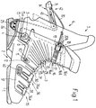
- a two-part shaft 3 is pivotally articulated about two lateral connecting bolts 4, only one of which is visible, on a lower shell 2 provided with a sole 1 in the ankle and heel region.
- This two-part shaft 3 has a front shaft part 5 and a rear shaft part 6.
- the connecting bolts 4 form a common articulation axis for the front shaft part 5 and the rear shaft part 6 on the lower shell 2, which runs approximately at right angles to the longitudinal direction of the shoe and approximately parallel to the sole 1.
- the front shaft part 5 is designed as a tongue part.
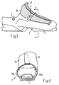
- the connecting bolts 4 protrude through a hole 7 in the lower shell 2 (see also FIG. 2), an elongated hole 8 in the front shaft part 5 (see also FIGS.
- the front shaft part 5 points to its a bore 10 on both lateral front lower end regions.
- the lower shell 2 has an elongated hole 11 in the corresponding area (see also FIG. 2).
- a pin 12 is passed through this bore 10 and the elongated hole 11. Thanks to the two approximately parallel elongated holes, namely the elongated hole 8 in the front shaft part 5 and the elongated hole 11 in the lower shell 2, the two-part shaft 3 can not only be pivoted relative to the lower shell 2, but the front shaft part 5 can also be translational, in one with respect to one Vertical to the sole 1 forwardly inclined direction, to be moved relative to the lower shell 2.
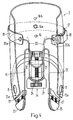
- the connecting pin 4 has at its two ends, in a manner known per se, on heads which are not described in more detail. Serves for translational displacement of the front shaft part 5 a cable 13 which is fastened with its two ends 13a to the front shaft part 5 below the elongated hole 8 according to FIGS. 1 and 4 and which is passed through a tensioning lever 14.
- a steel band 15 is fastened to the upper end region of the front shaft part 5 approximately in the middle by means of a screw 16.
- the steel band 15 can be fastened to the front shaft part 5 in three different positions one above the other with the aid of this screw 16. These three positions are indicated by the reference numerals 16a, 16b and 16c, the steel strip 15 being in its lowest position 16a in FIG. 1 and in its middle position 16b in FIG. 4.
- a ratchet band 17 having teeth is connected to the steel band 15. This ratchet strap 17 is in engagement with a latch 18, which is mounted in a holder 19.
- Another cable 20 is fastened with its one end 20a to the end of the steel band 15 remote from the ratchet band 17 and with its other end 20b to the bracket 19 supporting the latching pawl 18, and also, like the cable 13, through the tensioning lever 14.
- the bracket 19 with the latch 18 is slidable along the ratchet belt (or toothed belt) 17.
- the further cable 20 is passed through a housing 21 of the tensioning lever 14 mounted on the rear shaft part 6 and the cable 13 is passed through a slide 22 which can be displaced in the tensioning lever 7 (see FIGS. 1 and 4).
- the carriage 22 can be displaced in the longitudinal direction of the housing 21 with the aid of a screw 23 which is rotatably mounted in the housing 21 and which carries an adjusting wheel 24.
- the tension of the cable 13 can be changed and thus changed the tensile force that the cable 13 exerts on the front shaft part 5.
- the cable 13 is guided over two deflection pieces 25 on the shoulder 26 which can be removed from the lower shell 2.
- Each deflection piece 25 is elastically supported in the shoulder 26 by means of springs 27 (see also FIG. 4).
- the cable 13 with the tensioning lever 14 forms a tensioning device for the front shaft part 5, the lower part of which, which covers the lower shell 2 in the transition region between the foot and lower leg, is also referred to as the instep saddle 28.
- the front shaft part 5 has a number of undulating elevations 29 which run transversely to the longitudinal direction of the shoe.
- the lower shell 2 or foot shell also has a stop bar 30 running over the instep, which, by interacting with a front edge 31 of the front shaft part 5, limits the swiveling of the front shaft part 5 in relation to the lower shell 2 to the front and enables a force transmission when the leg is moved.
- the lower shell 2 has relatively rigid side walls 32a and 32b (FIG. 3) on both sides. Less rigid, ie relatively soft, overlapping tabs 33 and 34 are fastened to these side walls 32a and 32b. These flaps 33, 34 cover the driver's foot in the forefoot and instep area. The coverage of these tabs can be changed with the aid of a further tensioning device, hereinafter referred to as the first tensioning device 35, ie the tabs 33, 34 can be more or less contracted according to the foot volume.
- This first tensioning device 35 has a pair of buckles 36, wherein, as can be seen from FIG. 5, the two buckles 36a have a common operating lever 37.
- Each of these buckles 36a consists of two parts 38a and 38b, which are connected to one another via a threaded bolt 38c.
- One part 38a of each buckle 36a is articulated on the actuating lever 37.
- the other part 38b of the buckle 36a is attached to a tab 33.
- the operating lever 37 with the buckle parts 38a is attached to the other tab 34.
- the width of the buckles 36a can be adjusted with the aid of the threaded bolts 38c.
- the actuating lever 37 has a spring tongue 39, by means of which the opening angle of the lower shell 2 is elastically limited, ie the overlap of the tabs 33 and 34 cannot be reduced as far as desired with the buckles 36a open.
- the skier can fasten the buckles 36a without bending with the help of the ski pole tip.
- the ski pole tip is pressed into a recessed closing recess 40 of the actuating lever 37.
- the two buckles 36a form the first tensioning device 35, which is located in the forefoot and instep area of the ski boot and, as said, serves to pull together the flaps 33 and 34.
- a third tensioning device 45 is formed by the tensioning lever 14 and the cable 13 articulated on the slide 22.
- the front shaft part 5 and the rear shaft part 6 are designed somewhat differently than in the first exemplary embodiment according to FIGS. 1-6. Both the front shaft part 5 and the rear shaft part 6 are pivoted about the connecting bolts 4 on the lower shell 2. In contrast to the first The exemplary embodiment according to FIGS. 1-6 is located in the second exemplary embodiment according to FIG. 7 in the area of the connecting bolts 4 of the rear shaft part 6 under the front shaft part 5 provided with an elongated hole 8.
- the two-part shaft 3 with the front shaft part 5 and the rear shaft part 6 is open the lower shell 2 is not only pivotally articulated, but the front shaft part 5 can also be moved translationally, since here too, as in the exemplary embodiment according to FIGS 5 and the other slot 11 is in the lower shell 2.
- a tensioning lever 41 is articulated in the region above the heel on the rear shaft part 6 and in turn serves to move the front shaft part 5 with respect to the lower shell 2 with the aid of a cable 13.
- the cable 13 is also guided via a deflection piece (not shown) on the shoulder 26.
- the shaft is formed by a sleeve 46 instead of by a front shaft part and a rear shaft part, which is articulated on the lower shell 2 in the ankle area via connecting bolts 47.
- This cuff 46 surrounds the lower leg and has two overlapping tabs 48a and 48b on its front. These tabs 48a, 48b can be pulled together or closed with the aid of a corresponding second tensioning device 43, namely two buckles 49.
- a separate instep saddle 50 is arranged between the cuff 46 and the lower shell 2, which engages over the lower shell 2 and which can be tensioned in the direction of the heel with the aid of a buckle 51 and a cable 52, forming the third tensioning device 45.
- the lower shell 2 is otherwise constructed exactly the same as in the second exemplary embodiment according to FIG. 7.
- the first tensioning device 35 is also constructed in the same way as in the second exemplary embodiment according to FIG. 7.
- Two individual buckles 44 are used to pull the lower shell 2 together, by means of which an adjustment is made is possible with different foot volumes.
- the aforementioned buckles 49 on the cuff 46 allow adaptation to the circumference of the lower leg.
- the pivoting of the cuff 46 towards the tip of the shoe is elastically cushioned with the help of the separate instep saddle 50.
- the instep saddle 50 also transmits the forward movement of the shaft, i.e. the cuff 46, over the lower shell 2 on the ski. This power transmission from the lower leg to the ski is essential.
- a stop bar 53 is arranged on the collar 46 and a stop bar 30 is arranged on the lower shell 2.
- the upper and lower edges 54 of the separate instep saddle 50 are pressed onto these stop strips 53 and 30.
- the valleys present in the instep saddle 28, 50 between the undulating elevations 29 in the instep saddle 28, 50 can be equipped with rubber bodies 55 with which the flexurally elastic properties in the area of the instep saddle 28, 50 can be influenced.
- the cable 52 is fastened to the buckle 51 with its two ends 52a.
- a deflection, not shown, for the cable 52 is attached on the other side of the lower shell 2, a deflection, not shown, for the cable 52 is attached.
- This cable 52 runs in valleys between the elevations 29 and through cable guides 56 in the separate instep saddle 50 (FIG. 9).
- the structure of the described exemplary embodiments of the ski boot according to the invention is as follows:
- the first clamping device 35 serves to adapt the lower shell 2 to the foot volume.
- the second tensioning device 42 serves to adapt the shaft 3 or the sleeve 46 to the leg circumference.
- the third tensioning device 45 is used to make the ski boot adaptable in the area of the instep bend via the instep saddle 28 and 50, ie to create a balance between different foot volume and different circumference of the lower leg.
- the lower shell 2 encloses the forefoot to the instep with flaps 33 and 34 and is designed in the rear area similarly to that of a rear entry shoe, ie the lower shell 2 only encloses the heel there.
- the lower shell 2 has a stop bar 18 behind the tabs 33, 34 and behind the first tensioning device 35.
- This stop bar 30 thus forms a power transmission element.
- the instep saddle 28, 50 can be elastically deformed transversely to the longitudinal axis of the ski boot in order to improve its bending characteristic when the shaft moves forward in the longitudinal direction of the shoe with the aid of the wave-shaped elevations 29. Rubber bodies 55 can be arranged between these undulating elevations.
- the deflection piece 25 of the third tensioning device 45 can be exchangeable, as shown in FIG. 1, in order to be able to use buffers of different elasticity.
- the second and third tensioning devices 42, 45 can be coupled to one another (FIG. 1) or they may be independent of one another (FIGS. 7 and 8).
Landscapes
- Health & Medical Sciences (AREA)
- General Health & Medical Sciences (AREA)
- Physical Education & Sports Medicine (AREA)
- Footwear And Its Accessory, Manufacturing Method And Apparatuses (AREA)
Applications Claiming Priority (2)
| Application Number | Priority Date | Filing Date | Title |
|---|---|---|---|
| CH287892 | 1992-09-10 | ||
| CH2878/92 | 1992-09-10 |
Publications (1)
| Publication Number | Publication Date |
|---|---|
| EP0586801A1 true EP0586801A1 (fr) | 1994-03-16 |
Family
ID=4243611
Family Applications (1)
| Application Number | Title | Priority Date | Filing Date |
|---|---|---|---|
| EP93109588A Withdrawn EP0586801A1 (fr) | 1992-09-10 | 1993-06-16 | Chaussure de ski |
Country Status (2)
| Country | Link |
|---|---|
| EP (1) | EP0586801A1 (fr) |
| JP (1) | JPH06169801A (fr) |
Cited By (5)
| Publication number | Priority date | Publication date | Assignee | Title |
|---|---|---|---|---|
| DE4444299A1 (de) * | 1994-12-13 | 1996-06-20 | Kneissl Dachstein Sportartikel | Skischuh |
| EP0752215A3 (fr) * | 1995-07-07 | 1997-07-09 | Roces Srl | Chaussure de sport |
| EP1208758A3 (fr) * | 2000-11-20 | 2002-08-14 | Kneissl & friends Ges.m.b.H. | Chaussure de surf et de ski |
| DE102009005190A1 (de) * | 2009-01-20 | 2010-07-22 | Protecnology Gmbh | Schuh mit einer zwischen Sohle und Schaft wirkenden Zugelementanordnung |
| FR3050619A1 (fr) * | 2016-04-28 | 2017-11-03 | Pierre Gignoux | Tensionneur pour serrage de chaussure |
Citations (3)
| Publication number | Priority date | Publication date | Assignee | Title |
|---|---|---|---|---|
| EP0053340A2 (fr) * | 1980-11-28 | 1982-06-09 | Raichle Sportschuh AG | Chaussure de sport, en particulier chaussure de ski |
| EP0419922A2 (fr) * | 1989-09-26 | 1991-04-03 | Raichle Sportschuh AG | Chaussure de ski |
| EP0470539A2 (fr) * | 1990-08-10 | 1992-02-12 | HTM SPORT S.p.A. | Chaussure de ski |
Family Cites Families (2)
| Publication number | Priority date | Publication date | Assignee | Title |
|---|---|---|---|---|
| US4281468A (en) * | 1979-08-16 | 1981-08-04 | Comfort Products, Inc. | Ski boot having a corrugated front portion |
| CH674300A5 (fr) * | 1987-11-20 | 1990-05-31 | Raichle Sportschuh Ag |
-
1993
- 1993-06-16 EP EP93109588A patent/EP0586801A1/fr not_active Withdrawn
- 1993-09-10 JP JP22591293A patent/JPH06169801A/ja active Pending
Patent Citations (3)
| Publication number | Priority date | Publication date | Assignee | Title |
|---|---|---|---|---|
| EP0053340A2 (fr) * | 1980-11-28 | 1982-06-09 | Raichle Sportschuh AG | Chaussure de sport, en particulier chaussure de ski |
| EP0419922A2 (fr) * | 1989-09-26 | 1991-04-03 | Raichle Sportschuh AG | Chaussure de ski |
| EP0470539A2 (fr) * | 1990-08-10 | 1992-02-12 | HTM SPORT S.p.A. | Chaussure de ski |
Cited By (5)
| Publication number | Priority date | Publication date | Assignee | Title |
|---|---|---|---|---|
| DE4444299A1 (de) * | 1994-12-13 | 1996-06-20 | Kneissl Dachstein Sportartikel | Skischuh |
| EP0752215A3 (fr) * | 1995-07-07 | 1997-07-09 | Roces Srl | Chaussure de sport |
| EP1208758A3 (fr) * | 2000-11-20 | 2002-08-14 | Kneissl & friends Ges.m.b.H. | Chaussure de surf et de ski |
| DE102009005190A1 (de) * | 2009-01-20 | 2010-07-22 | Protecnology Gmbh | Schuh mit einer zwischen Sohle und Schaft wirkenden Zugelementanordnung |
| FR3050619A1 (fr) * | 2016-04-28 | 2017-11-03 | Pierre Gignoux | Tensionneur pour serrage de chaussure |
Also Published As
| Publication number | Publication date |
|---|---|
| JPH06169801A (ja) | 1994-06-21 |
Similar Documents
| Publication | Publication Date | Title |
|---|---|---|
| EP0321714B1 (fr) | Chaussure de ski | |
| DE4435113C1 (de) | Snowboardbindung | |
| DE19642887C2 (de) | Bindung für Sportgeräte | |
| DE3153702C2 (de) | Skibindung | |
| DE19653162C1 (de) | Snowboardbindung | |
| DE3236259C2 (de) | Skistiefel | |
| EP0316540B1 (fr) | Chaussure de sport, en particulier chaussure de ski | |
| DE60009019T2 (de) | Schuh mit hohem Schaft und Schnürverschluss | |
| DE60318809T2 (de) | Bindung mit verlagerter Energie | |
| AT397193B (de) | Skischuh | |
| DE2709694C2 (de) | Skistiefel | |
| CH650387A5 (de) | Sportschuh, insbesondere skischuh. | |
| CH577282A5 (en) | Ski boot with hinged rear ankle support - has simple fastening and tightening mechanism with interconnected tension members | |
| EP0259896B1 (fr) | Chaussure de sport, en particulier chaussure de ski | |
| DE69100203T2 (de) | Skischuhe mit schwenkbarem Vorderschaft. | |
| DE69303554T2 (de) | Vorrichtung zum Festklemmen des Oberteils eines Skistiefels | |
| DE4010118A1 (de) | Bindungsvorrichtung eines paares von schuhen eines skilaeufers auf einem gleitbrett auf schnee | |
| AT523145B1 (de) | Schuh, insbesondere Einsatzstiefel, mit einem Schuh-Schnürsystem | |
| DE102008006267B3 (de) | Snowboardbindung | |
| EP0567895A1 (fr) | Chaussure de ski | |
| AT401216B (de) | Skischuh | |
| DE2708329A1 (de) | Selbstausloesende sicherheitsskibindung | |
| AT396863B (de) | Skischuh | |
| EP0594554A1 (fr) | Chaussure de ski | |
| AT526739B1 (de) | Skischuh |
Legal Events
| Date | Code | Title | Description |
|---|---|---|---|
| PUAI | Public reference made under article 153(3) epc to a published international application that has entered the european phase |
Free format text: ORIGINAL CODE: 0009012 |
|
| 17P | Request for examination filed |
Effective date: 19931123 |
|
| AK | Designated contracting states |
Kind code of ref document: A1 Designated state(s): AT CH DE FR IT LI |
|
| 17Q | First examination report despatched |
Effective date: 19941219 |
|
| STAA | Information on the status of an ep patent application or granted ep patent |
Free format text: STATUS: THE APPLICATION IS DEEMED TO BE WITHDRAWN |
|
| 18D | Application deemed to be withdrawn |
Effective date: 19950503 |