EP0586868A2 - Dispositif d'entraînement d'un corps rotatif pour un appareil de formation d'images - Google Patents
Dispositif d'entraînement d'un corps rotatif pour un appareil de formation d'images Download PDFInfo
- Publication number
- EP0586868A2 EP0586868A2 EP93112199A EP93112199A EP0586868A2 EP 0586868 A2 EP0586868 A2 EP 0586868A2 EP 93112199 A EP93112199 A EP 93112199A EP 93112199 A EP93112199 A EP 93112199A EP 0586868 A2 EP0586868 A2 EP 0586868A2
- Authority
- EP
- European Patent Office
- Prior art keywords
- rotational
- driving
- photoreceptor
- roller
- driving device
- Prior art date
- Legal status (The legal status is an assumption and is not a legal conclusion. Google has not performed a legal analysis and makes no representation as to the accuracy of the status listed.)
- Granted
Links
Images






Classifications
-
- G—PHYSICS
- G03—PHOTOGRAPHY; CINEMATOGRAPHY; ANALOGOUS TECHNIQUES USING WAVES OTHER THAN OPTICAL WAVES; ELECTROGRAPHY; HOLOGRAPHY
- G03G—ELECTROGRAPHY; ELECTROPHOTOGRAPHY; MAGNETOGRAPHY
- G03G15/00—Apparatus for electrographic processes using a charge pattern
- G03G15/75—Details relating to xerographic drum, band or plate, e.g. replacing, testing
- G03G15/757—Drive mechanisms for photosensitive medium, e.g. gears
-
- G—PHYSICS
- G03—PHOTOGRAPHY; CINEMATOGRAPHY; ANALOGOUS TECHNIQUES USING WAVES OTHER THAN OPTICAL WAVES; ELECTROGRAPHY; HOLOGRAPHY
- G03G—ELECTROGRAPHY; ELECTROPHOTOGRAPHY; MAGNETOGRAPHY
- G03G15/00—Apparatus for electrographic processes using a charge pattern
- G03G15/75—Details relating to xerographic drum, band or plate, e.g. replacing, testing
- G03G15/751—Details relating to xerographic drum, band or plate, e.g. replacing, testing relating to drum
-
- Y—GENERAL TAGGING OF NEW TECHNOLOGICAL DEVELOPMENTS; GENERAL TAGGING OF CROSS-SECTIONAL TECHNOLOGIES SPANNING OVER SEVERAL SECTIONS OF THE IPC; TECHNICAL SUBJECTS COVERED BY FORMER USPC CROSS-REFERENCE ART COLLECTIONS [XRACs] AND DIGESTS
- Y10—TECHNICAL SUBJECTS COVERED BY FORMER USPC
- Y10T—TECHNICAL SUBJECTS COVERED BY FORMER US CLASSIFICATION
- Y10T74/00—Machine element or mechanism
- Y10T74/19—Gearing
- Y10T74/19623—Backlash take-up
Definitions
- the present invention relates to an image forming output apparatus such as a digital color copying apparatus, a digital color printer, and the like to which an electrophotographic process is applied.
- an image is formed in the following manner: a rotating cylindrical photoreceptor or a belt-shaped photoreceptor is rotated and electrostatic latent images are formed thereon successively; black toner and other color toners, in the case of color image formation, are adhered to the electrostatic latent images formed as described above for development; and they are transferred onto a recording sheet, thus, the image is obtained.
- the photoreceptor drum in the image output apparatus and a driving roller for the belt-shaped photoreceptor are referred to as a rotational body.
- the main consideration is that the objects driven by the driving device are appropriately located in the allowable space, while satisfying the values of the line speed or number of revolutions introduced from the product specification. That is, the following are main concerns: the method by which the driving power is transmitted from a driving power source to a driven object; and mechanical elements for power transmission.
- a bearing of a drive shaft of the photoreceptor is replaced with one made of sintered metal; a flywheel is connected with the drive shaft of the photoreceptor; a brake, in which a spring is combined with a friction material, is provided on the rotary shaft of the photoreceptor drum; the accuracy of a gear is enhanced; or a helical gear with various kinds of torsion angles is provided.
- the main factor of the rotational fluctuation of the driving system is the following: the rotational fluctuation per one rotation of the rotating shaft of a motor is large, and absolute values of fluctuation components per one rotation of a gear and per one tooth of a gear are large; and fluctuation components and their higher harmonic wave components cause a resonance phenomenon in relation to the proper oscillation frequency of the driving system.
- Fig. 14 shows the power spectrum of speed fluctuation of conventional apparatuses.
- fluctuation components of a gear according to the line speed proper to the apparatus are 176 Hz in the case of a gear directly coupled to the motor, 64 Hz in the case of a second shaft, and 25 Hz in the case of a gear directly coupled to a drum, and in this case, a higher harmonic wave component of 50 Hz is shown.
- a component of a rotation of the gear directly coupled to the motor is 22 Hz, and its higher harmonic wave component of 44 Hz is shown in the drawing.
- Fig. 15 shows an example in which a transfer function for obtaining numerically the proper oscillation frequency of the driving system was measured.
- the measurement was conducted in the following way: an output of an impact excitation hammer, and an output of a piezoelectric type pick-up sensor, provided to one end of a photoreceptor drum in order to measure the fluctuation of the acceleration in the rotation direction, were connected with a dual channel type FFT analyser; and a Fourier spectrum ratio was obtained. From Fig. 15, the following can be found: a peak of the proper oscillation frequency is near 45 Hz; and high level areas of the transfer function are spread to cover the range of 30 to 60 Hz.
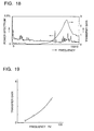
- Fig. 16 shows superimposition of the fluctuation component spectrum and the transfer function.
- the driving system it can be found from the drawing that a peak of the transfer function and the position of a frequency area, to which the fluctuation component and its second harmonics belong, are overlapped. That is, it is found that the driving system amplifies the fluctuation components (resonance is caused).
- a driving device for a rotational body was constituted as follows, with the transmission of the fluctuation component in the driving power transmission system, and the concept of the transfer function, resonance and proper oscillation frequency as well as a method to reduce the transmitted fluctuation, all taken into consideration.
- the proper oscillation frequency is expressed by the following equation.
- K indicates the torsional rigidity of the driving system
- I indicates its moment of inertia.
- the value of w can be changed by changing the value of K or I.
- the value of w may either be larger or smaller with respect to the fluctuation component of the driving system.
- the value of K is increased or the value of I is decreased.
- the value of I is increased or the value of K is decreased.
- Fig. 17 and Fig. 18 show the power spectrum of the rotational fluctuation and the actually measured value of the transfer function of the driving system in the case where the proper oscillation frequency is changed to a larger value and a smaller value by changing the structure of the driving system, wherein data are overlapped in the same manner as that in Fig. 16.
- Fig. 19 shows the comparison of peak values of the transfer function of the foregoing three driving systems.
- the value of K which is the torsional rigidity of the driving system, is decreased.
- the transfer function is decreased together with a change of the number of the proper oscillation in the case where the structure is changed in order to reduce the torsional rigidity K of the driving system so that the proper oscillation frequency is changed to a lower frequency side, wherein the proper oscillation frequency is changed in order to prevent the resonance. It is considered that the foregoing effect can be obtained in the following manner: when the structure is changed in order to change the proper oscillation frequency, the attenuation coefficient is increased due to the change to the flexible structure; and the structure is changed so that the rotational fluctuation is absorbed in the driving system itself.
- an image with high quality can not be obtained when the rotational body is not rotated constantly at a predetermined speed.
- the rotational speed is changed, distance between scanning lines of the laser beam is different at each position, so that ununiform image density is generated.
- colors, generally yellow, magenta, cyan, and black toners are superimposed, and therefore the color toner balance is lost and the color reproducibility is lowered.
- the first embodiment of the present invention is constituted as follows: the rotational body is connected with a driving shaft at a position which is far from the driving transmission system; a load having large inertia is provided in the rotational body so that the proper oscillation frequency of the rotational body is lowered; and a rotational member having rotational resistance is brought into contact with a non-image portion, that is, the portion which is not concerned with image formation on the rotational body.
- the proper oscillation frequency can be separated from the frequency of the fluctuation component, and the resonance of the driving system of the rotational body can be prevented so that the speed fluctuation of the rotational body is decreased, due to the following reasons: the effective length of the driving shaft is long because the driving shaft is connected with the rotational body at a position which is far from the driving transmission system; rigidity K of a portion beyond the drive gear is actually decreased; moment of inertia I is increased because a load providing large inertia is provided to the rotational body, and therefore the proper oscillation frequency is decreased; and thereby the proper oscillation frequency of the driving system of the rotational body shown by Equation 1 is decreased.
- rigidity K of the driving system of the rotational body is practically lowered, therefore the structure can be made flexible, the transfer gain of the driving system of the rotational body is decreased, and thereby a speed fluctuation level of the rotational body can be decreased. Further, since the rotational member having rotational resistance is in contact with the non-image portion of the rotational body, the speed fluctuation of the rotational body can be rapidly absorbed, and thereby the quality of outputted images can be greatly improved. Further, the device can be made smaller, the cost is decreased, and the reliability of the entire system can be increased.
- the second embodiment of the present invention is constituted in the following manner: in order to rapidly absorb the speed fluctuation caused by the impulsive force described above, to maintain the speed constant, and thereby to improve the image quality, a rotational member having rotational resistance is caused to be in contact with the non-image portion, that is, a corner portion which is not directly concerned with image formation, or the side surface of the rotational body so that sliding resistance is given to the rotational body.
- the third embodiment of the present invention is constituted in the following manner: in order to rapidly absorb the speed fluctuation caused by the foregoing impulsive force, to maintain the constant speed, and thereby to improve the image quality, a blade made of rubber or a pad made of non woven fabric is caused to be in contact with non-image portion of the rotational body, that is, a corner portion which is not directly concerned with image formation, or the side surface of the rotational body so that sliding resistance is given to the rotational body.
- the stabilization time for impulsive load variation such as pressure contact or release of a cleaning blade can be reduced, and the oscillation can be rapidly absorbed.
- the speed fluctuation of the rotational body caused when the load is varied is decreased, and the image quality can be greatly improved.
- the apparatus can be made compact, the cost can be lowered, and further, reliability of the entire system can be increased.
- Fig. 12 shows the entire structure of an electrophotographic image output apparatus using a rotational body of the present invention.
- a photoreceptor drum 2 used for the rotational body, a developing section 3, and a driving mechanism, by which the photoreceptor drum 2 is driven, are provided in an electrophotographic output apparatus 31.
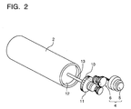
- the photoreceptor drum 2 and its driving mechanism 4 are shown in Fig. 2.
- the driving mechanism 4 is composed of a driving motor 5 and a gear group 6 connected therewith.
- a final gear 10 of the gear group 6 is connected with a driving gear 11 of the photoreceptor drum 2.
- the photoreceptor drum 2 is composed of a cylindrical aluminum member, on the side of which organic light-sensitive material is coated, and flanges 12a and 12b are provided on both ends of the member as shown in Fig. 1.
- a drive shaft 13 is provided through the center of flanges 12a and 12b.
- the flange 12b which is far from the driving gear 11, is fixed to the drive shaft 13 by a pin 15, and the flange 12a provided near the drive gear 11 is rotatably provided on the drive shaft 13.
- the drive shaft 13 is rotatably supported by a bearing 21, and the drive gear 11 is provided on the shaft end, and engaged with the final gear 10.
- Inertia members 8 are respectively provided to both flanges 12a and 12b inside the photoreceptor drum 2.
- the inertial members 8 are structured as follows: the inertial member 8 is made of steel material, stainless steel, brass material or the like; the material is formed into a ring; and rings are superimposed. The larger its specific gravity is, the more compact the inertial member 8 can be formed. Preferably, a ratio of moment of inertia 11 of the photoreceptor drum 2 to moment of inertia 12 of the inertial member 8 is within the range of 0.05 to 0.4.
- a rotational member 18 is shown in Fig. 3.
- the rotational member 18 is composed of a support shaft 19 and a roller 20 which is rotatably provided on the support shaft 19, and a high viscosity oil is coated therebetween.
- the roller 20 is composed of a metallic inner cylinder 23 and an outer cylinder 22 which is made of rubber and by which the outside of the inner cylinder 23 is covered.
- the rotating member 18 is structured as follows: the roller 20 is in contact with a corner, that is, a portion which is not concerned with image formation, of the photoreceptor drum 2; and the support shaft 19 is provided so that it is in parallel with the drive shaft 13 of the photoreceptor drum 2. Accordingly, when the photoreceptor drum 2 is rotated, the roller 20 having viscous friction with the support shaft 19 is rotated, and thereby, the photoreceptor drum 2 is subjected to rotational resistance while being rotated.
- Equation 2 shows that when an attenuation coefficient ? is increased, the transfer function G(s) is decreased.
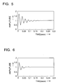
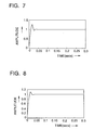
- Figs. 5 to 8 show the difference between attenuation conditions when the attenuation coefficient is changed.
- An axis of ordinates in each drawing indicates an amplitude, and an axis of abscissas indicates time.
- the attenuation coefficients are 10 % in Fig. 5, 20 % in Fig. 6, 40 % in Fig. 7, and 60 % in Fig. 8.
- the attenuation coefficient ? is preferably within 20 to 60 %.
- the flange 12b which is far from the drive gear 11, is connected with the drive shaft 13, the inertial member 8 is provided inside the photoreceptor drum 2, and the rotational member 18 is in contact with the photoreceptor drum 2. Therefore, moment of inertia I of the driving system composed of the photoreceptor drum 2, the drive shaft 13 and the drive gear 11, is increased. Further, the distance from the drive gear 11 to the inertial member 8 is increased, and the rigidity K of the driving system is practically decreased, so that the proper oscillation frequency of the driving system is lowered.
- the proper oscillation frequency can be separated from the frequency of the fluctuation component in relation to the frequency of the fluctuation component generated in the driving mechanism 4; the resonance of the photoreceptor drum 2 can be prevented; the photoreceptor drum can be smoothly rotated without any speed fluctuation; and thereby, the image quality can be greatly improved.
- the following effects can be obtained: since rigidity K is practically decreased, the transfer gain of the photoreceptor drum 2 is lowered; therefore, the speed fluctuation which is caused by the final gear 10 is easily attenuated; the rotational speed fluctuation of the photoreceptor drum 2 can be lowered; since the rotational member 18 is in contact with the photoreceptor drum 2, the attenuation coefficient ? of the photoreceptor drum 2 is increased; even when an instantaneous speed fluctuation is caused, for example, when the cleaning blade is pressed onto the photoreceptor drum 2, the speed fluctuation is rapidly attenuated, the speed is returned to the original one, and the rotational speed fluctuation can be minimized. Consequently, the image quality can be greatly improved.
- Fig. 4 shows another example of the photoreceptor drum 2.
- the flanges 12a and 12b are composed of members having a heavy inertial load, and the flange 12a is rotatably provided on the drive shaft 13.
- moment of inertia I of the driving system is increased, the inertial load of the the flange itself may be increased as described above. In this way, as described above, the speed fluctuation is decreased, the image quality can be improved, assembling processes can be simplified, and the number of parts can be decreased, so that the cost can be lowered.
- the inertial member 8 may be structured in the following way: metallic plates in the form of thin plate are laminated; and they are fixed to flanges 12a and 12b.
- the inertial member 8 is structured as described above, the following effects can be obtained: moment of inertia I of the photoreceptor drum 2 is increased; rigidity K is decreased and the proper oscillation frequency is decreased; as a result of that, the proper oscillation frequency can be separated from the frequency of the fluctuation component in the frequency area; the resonance can be prevented; the speed fluctuation of the photoreceptor drum 2 is decreased; and thereby, the image quality is greatly improved. Further, when the number of metallic plates are adjusted, moment of inertia I can be easily adjusted.
- Rotational resistance of the rotational member 18 can be appropriately set by selecting the viscosity of oil which is poured into a gap between the roller 20 and the support shaft 19.
- Fig. 9 shows another example of the rotational member 18.
- a groove 24 is formed along the circumference inside the inner cylinder 23, and a high viscosity oil is filled in the groove 24.
- FIG. 10 Yet another example is shown in Fig. 10.
- the groove 24 is provided in the inner cylinder 23 in the same manner as that of the rotational member 18 shown in Fig. 9, and baffle plates 27 are provided on the support shaft 19 at four locations as shown in Fig. 11, and protruded towards the groove 24.
- the baffle plates 27 provided on the support shaft 18 prevent the viscous oil from being moved with the roller 20, and thereby larger resistance can be obtained. Accordingly, the attenuation coefficient ?
- the baffle plates 27 may also be provided on the roller 20 side.
- the flange 12a is slidably provided on the driving shaft 13, however a sliding bearing or a ball bearing may be provided on the portion.
- a sliding bearing or a ball bearing may be provided on the portion.
- the rotational body is the photoreceptor drum 2.
- the photoreceptor drum 2 does not necessarily need to be the rotational body of the present invention.
- the photoreceptor drum 2 may be replaced with a belt-shaped photoreceptor 25 driven by a driving roller 26 to which the rotational body of the present invention is applied in an image output apparatus.
- a rotational member 18 or a sliding member 50 which will be described later, may be provided in the apparatus.
- the driving roller 26 can be rotated without any speed fluctuation. Accordingly, the photoreceptor 25 can be conveyed at a constant speed, and therefore, the image quality can be greatly improved.
- the flange 12b which is far from the driving gear 11, is fixed to the driving shaft 13 so that rigidity K is practically decreased; and the inertial member 8 is provided to the rotational body of the photoreceptor drum 2 or the like so that moment of inertia I of the rotational body driving system is increased, the proper oscillation frequency is lowered so that it does not match with the frequency of the speed fluctuation which is transmitted to the rotational body driving system. Accordingly, the following effects can be obtained: the resonance of the photoreceptor drum 2 or driving roller 26 can be prevented; the photoreceptor drum 2 or the photoreceptor 25 can be rotated or conveyed at a constant speed without any speed fluctuation; and thereby, the image quality can be greatly improved.
- the transfer gain of the photoreceptor drum 2 or the driving roller 26 is lowered, the speed fluctuation is hardly transmitted, the speed fluctuation of the photoreceptor drum 2 or the photoreceptor 25 can be decreased, and when the rotational member 18 is contacted with the non-image portion of the photoreceptor drum 2, the attenuation coefficient ? of the photoreceptor drum 2 or the driving roller 26 can be increased, the instantaneous speed fluctuation caused by operations of the cleaning blade or the like, can be stabilized in a small period of time, and therefore the image quality is greatly improved. Further, the mechanism can be made compact, and thereby the apparatus can be made compact, so that the cost can be lowered. Further, reliability of the entire system is greatly increased.
- the rotational body driving device of the present invention in the rotational body driving system comprising the driving shaft, which is connected with the driving motor and driven thereby, and the rotational body which is connected with the driving shaft and rotated at a constant speed, when the flange which is far from the driving gear provided on the driving shaft, is fixed to the driving shaft, the inertial load is provided inside the rotational body, and further the sliding member is contacted with the non-image portion of the rotational body, the following effects can be obtained; the driving system can be set so that the proper oscillation frequency of the driving system is lowered, the frequency of the fluctuation component, which is generated by the driving motor and the rotation of the gear connected with the motor, does not match with the proper oscillation frequency; the resonance of the rotational body can be prevented; and the rotational body can be rotated without any speed fluctuation.
- the rigidity is practically decreased; thereby the transfer gain of the rotational body driving system can be lowered; the transmission of the fluctuation can be prevented; the speed fluctuation of the rotational body can be decreased; attenuation coefficient ? of the rotational body driving system can be increased when the rotational member is contacted with the rotational body; the instantaneous speed fluctuation can be stabilized in a short period of time; and therefore the image quality can be greatly improved.
- an uneven image which is called jittering or an uneven pitch, which is generated particularly in the subsidiary scanning direction of the writing system, is decreased, and therefore the image quality can be greatly improved.
- the apparatus the mechanism of which is complicated, and the size of which is large in the conventional technology, can be made simple and compact, and thereby the cost can be lowered. Further, since the mechanism is made simple, the reliability of the entire system can be greatly improved.
- Fig. 20 is a sectional view of the photoreceptor drum 2 according to another example.
- the photoreceptor drum 2 is made of a cylindrical aluminum material, on the side of which an organic photosensitive material is coated, and on both ends of which flanges 12 are fixed.
- a driving shaft 13 is provided in the center of the flange 12.
- the driving shaft 13 is rotatably supported by a bearing 21.
- the driving gear 11 is provided on one end of the shaft, and engaged with the final gear 10.
- the rotational member 18, shown in Fig. 3, Figs. 9, 10 and 11, is provided on the side of the flange 12, that is, on the wall of the image output apparatus 31.
- the roller 20 having viscous material between the support shaft 19 and the roller itself is made to be in contact with the photoreceptor drum 2 to rotate together with it, the attenuation coefficient ? of the photoreceptor drum 2 is increased. Therefore, for example, even when the instantaneous speed fluctuation is caused in the case where the cleaning blade touches the photoreceptor drum 2, the speed fluctuation can be rapidly attenuated and the speed can return to the original one, and the the fluctuation of the rotational speed can be minimized. Accordingly, the instantaneous speed fluctuation can be rapidly attenuated, the photoreceptor drum 2 can be smoothly rotated at a constant speed, and thereby the image quality can be greatly improved.
- the rotational body driving device of the present invention when a roller having high viscous material between a support shaft and the roller itself is made to be in contact with a non-image forming portion of the rotational body to rotate together with it, the attenuation coefficient of the rotational body can be increased, and the rotational body can be constantly rotated at a predetermined speed irrespective of the speed fluctuation caused by the contact of a cleaning blade to the photoreceptor, or the like.
- Fig. 21 is a sectional view of the photoreceptor drum 2 of another example.
- the photoreceptor drum 2 is made of a cylindrical aluminum material, on the side of which an organic photosensitive material is coated, and on both ends of which flanges 12 are fixed.
- a driving shaft 13 is provided in the center of the flange 12.
- the driving shaft 13 is rotatably supported by a bearing 21.
- the driving gear 11 is provided on one end of the shaft, and engaged with the final gear 10.
- a sliding member 50 is provided on the side of the flange 12, that is, on a wall of the image output apparatus 31.
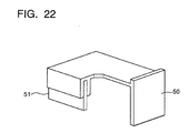
- the sliding member 50 is provided with a blade 51 made of silicone rubber on the end of the member as shown in Fig. 22, and the blade 51 is in contact with a corner of the photoreceptor drum 2, that is, a portion which is out of the image formation area.
- the sliding member 50 gives sliding resistance onto the photoreceptor drum 2 when the blade 51 is in contact with it.
- the sliding resistance can be appropriately set by adjusting the pressing force of the blade 51 or its material.
- the attenuation coefficient ? of the photoreceptor drum 2 is increased; even when the instantaneous speed fluctuation is generated, for example, in the case where the cleaning blade touches the photoreceptor drum 2, the speed fluctuation can be rapidly attenuated so that the speed can return to the original speed; and the fluctuation of the rotational speed can be minimized. Accordingly, the instantaneous speed fluctuation can be rapidly attenuated, and thereby, the image quality can be greatly improved.
- the sliding member 50 is not directly in contact with the surface of the photoreceptor drum 2, but it keeps contact with the flange 12 on the side.
- the attenuation coefficient ? of the photoreceptor drum 2 can be increased, and the instantaneous speed fluctuation caused by the contact of the cleaning blade to the photoreceptor or the like, can be rapidly attenuated, so that the rotational speed can be maintained constant.
- the material of the cleaning blade 51 provided on the tip of the sliding member 50 is not limited to silicone rubber, but urethane rubber, polyurethane rubber, and other high polymer material or elastic material may be used. Further, as another example, a blade 51 provided on the tip of the sliding member 50 may be replaced with a pad made of flocked fabric member, non woven fabric member, or other fabric member.
- the attenuation coefficient ? of the photoreceptor drum 2 or the driving roller 26 can be increased, the instantaneous speed fluctuation caused by operations of the cleaning blade or the like, can be stabilized in a small period of time, and therefore the image quality is greatly improved. Further, the mechanism can be made compact, and thereby the apparatus can be made compact, so that the cost can be lowered. Further, reliability of the entire system is greatly increased.
- the rotational body driving device of the present invention when a sliding member composed of a blade or pad is brought into contact with a non-image forming portion of the rotational body to increase the attenuation coefficient of the rotational body, the rotational body can be constantly rotated at a predetermined speed irrespective of the speed fluctuation caused by the contact of a cleaning blade to the photoreceptor, or the like.
- an uneven image which is called jittering or an uneven pitch, which is generated particularly in the subsidiary scanning direction of the writing system, is decreased, and therefore the image quality can be greatly improved.
- the apparatus the mechanism of which is complicated, and the size of which is large in the conventional technology, can be made simple and compact, and thereby the cost can be lowered. Further, since the mechanism is made simple, the reliability of the entire system can be greatly improved.
Landscapes
- Physics & Mathematics (AREA)
- General Physics & Mathematics (AREA)
- Discharging, Photosensitive Material Shape In Electrophotography (AREA)
- Electrophotography Configuration And Component (AREA)
Applications Claiming Priority (6)
| Application Number | Priority Date | Filing Date | Title |
|---|---|---|---|
| JP269408/92 | 1992-09-11 | ||
| JP26940892A JP3258393B2 (ja) | 1992-09-11 | 1992-09-11 | 画像出力機器 |
| JP269410/92 | 1992-09-11 | ||
| JP26941092A JPH0695558A (ja) | 1992-09-11 | 1992-09-11 | 回転体の駆動装置 |
| JP4271111A JPH0695569A (ja) | 1992-09-14 | 1992-09-14 | 回転体の駆動装置 |
| JP271111/92 | 1992-09-14 |
Publications (3)
| Publication Number | Publication Date |
|---|---|
| EP0586868A2 true EP0586868A2 (fr) | 1994-03-16 |
| EP0586868A3 EP0586868A3 (en) | 1994-08-17 |
| EP0586868B1 EP0586868B1 (fr) | 1998-03-18 |
Family
ID=27335722
Family Applications (1)
| Application Number | Title | Priority Date | Filing Date |
|---|---|---|---|
| EP93112199A Expired - Lifetime EP0586868B1 (fr) | 1992-09-11 | 1993-07-29 | Dispositif d'entraínement du tambour ou ruban photorecepteur rotatif pour un appareil de formation d'images |
Country Status (3)
| Country | Link |
|---|---|
| US (1) | US5323211A (fr) |
| EP (1) | EP0586868B1 (fr) |
| DE (1) | DE69317493T2 (fr) |
Cited By (1)
| Publication number | Priority date | Publication date | Assignee | Title |
|---|---|---|---|---|
| EP0586869A3 (fr) * | 1992-09-11 | 1995-04-12 | Konishiroku Photo Ind | Photorécepteur pour un appareil à copier. |
Families Citing this family (10)
| Publication number | Priority date | Publication date | Assignee | Title |
|---|---|---|---|---|
| US5420664A (en) * | 1992-09-02 | 1995-05-30 | Konica Corporation | Driving apparatus for a rotary body in use with an image forming apparatus |
| JPH07271130A (ja) * | 1994-03-29 | 1995-10-20 | Tec Corp | 画像形成装置 |
| US5461464A (en) * | 1994-11-03 | 1995-10-24 | Xerox Corporation | Photoreceptor assembly |
| JPH09185291A (ja) * | 1996-01-08 | 1997-07-15 | Fuji Xerox Co Ltd | 電子写真感光体の支持方法および駆動方法並びに画像 形成装置 |
| JPH10339354A (ja) * | 1997-06-09 | 1998-12-22 | Matsushita Electric Ind Co Ltd | 動吸振器及び動吸振器を用いたディスク記録再生装置 |
| US6138941A (en) * | 1998-01-28 | 2000-10-31 | Fuji Photo Film Co., Ltd. | Flange for hollow article |
| JP3635618B2 (ja) * | 1999-02-12 | 2005-04-06 | 株式会社リコー | 画像形成装置 |
| JP4066593B2 (ja) * | 2000-06-22 | 2008-03-26 | コニカミノルタホールディングス株式会社 | 回転安定装置、回転駆動機構、画像形成装置及び画像読取装置 |
| JP4465202B2 (ja) * | 2004-02-06 | 2010-05-19 | Hoya株式会社 | モータの制振取付構造 |
| JP5403289B2 (ja) | 2011-03-31 | 2014-01-29 | コニカミノルタ株式会社 | 像担持体駆動装置及びこれを備えた画像形成装置 |
Family Cites Families (7)
| Publication number | Priority date | Publication date | Assignee | Title |
|---|---|---|---|---|
| US4120576A (en) * | 1977-04-04 | 1978-10-17 | Xerox Corporation | Drum support apparatus |
| JPS57151955A (en) * | 1981-03-17 | 1982-09-20 | Fuji Xerox Co Ltd | Driving mechanism for image formation member |
| JPS5823036A (ja) * | 1981-08-05 | 1983-02-10 | Fuji Xerox Co Ltd | 複写機の感光ドラム制動装置 |
| JPS61179560U (fr) * | 1985-04-27 | 1986-11-08 | ||
| JP2713896B2 (ja) * | 1987-01-19 | 1998-02-16 | キヤノン株式会社 | 多色画像形成装置 |
| JP2553509Y2 (ja) * | 1990-10-15 | 1997-11-05 | 旭光学工業株式会社 | 感光体ドラムの回転ムラ防止構造 |
| US5218405A (en) * | 1992-06-29 | 1993-06-08 | Xerox Corporation | Photoreceptor drum runout control apparatus |
-
1993
- 1993-05-03 US US08/057,089 patent/US5323211A/en not_active Expired - Fee Related
- 1993-07-29 EP EP93112199A patent/EP0586868B1/fr not_active Expired - Lifetime
- 1993-07-29 DE DE69317493T patent/DE69317493T2/de not_active Expired - Fee Related
Cited By (1)
| Publication number | Priority date | Publication date | Assignee | Title |
|---|---|---|---|---|
| EP0586869A3 (fr) * | 1992-09-11 | 1995-04-12 | Konishiroku Photo Ind | Photorécepteur pour un appareil à copier. |
Also Published As
| Publication number | Publication date |
|---|---|
| EP0586868A3 (en) | 1994-08-17 |
| EP0586868B1 (fr) | 1998-03-18 |
| DE69317493T2 (de) | 1998-08-20 |
| US5323211A (en) | 1994-06-21 |
| DE69317493D1 (de) | 1998-04-23 |
Similar Documents
| Publication | Publication Date | Title |
|---|---|---|
| EP0585897B1 (fr) | Appareil d'entrainement pour faire tourner un corps rotatif pour l'emploi dans un appareil de formation d'images | |
| US5323211A (en) | Driving device of rotational body for use in image forming apparatus | |
| US5528348A (en) | Damping device for rotating members | |
| KR100765757B1 (ko) | 진동저감부재를 포함하는 화상형성장치 | |
| EP0867777B1 (fr) | Appareil d'entraînement d'un corps rotatif et appareil de formation d'images l'utilisant | |
| EP0586869B1 (fr) | Dispositif d'entraînement pour un photorécepteur | |
| US6456807B1 (en) | Rotation stabilizing device | |
| EP0896258B1 (fr) | Appareil de formation d'images | |
| JPH09222826A (ja) | 画像形成装置用の回転体駆動装置 | |
| EP0675413B1 (fr) | Appareil pour fabrication d'image | |
| EP0903641A1 (fr) | Dispositif d'entraínement pour un élément porteur d'images | |
| JP3364514B2 (ja) | 画像出力機器における回転体の駆動装置 | |
| EP0824229B1 (fr) | Appareil de formation d'images | |
| JP3258720B2 (ja) | 画像出力機器 | |
| JP3258393B2 (ja) | 画像出力機器 | |
| JP3258721B2 (ja) | 画像出力機器 | |
| JP3258719B2 (ja) | 画像出力機器 | |
| JP4289174B2 (ja) | 回転体の駆動装置及び画像形成装置 | |
| JP3258717B2 (ja) | 画像出力機器 | |
| JPH06133122A (ja) | 画像形成出力装置 | |
| JP3258388B2 (ja) | 画像出力機器 | |
| JP2005249109A (ja) | 回転体の駆動装置及び画像形成装置 | |
| JP3258722B2 (ja) | 画像出力機器 | |
| JPH0695558A (ja) | 回転体の駆動装置 | |
| JPH09292796A (ja) | 画像形成装置の感光体の制振装置 |
Legal Events
| Date | Code | Title | Description |
|---|---|---|---|
| PUAI | Public reference made under article 153(3) epc to a published international application that has entered the european phase |
Free format text: ORIGINAL CODE: 0009012 |
|
| AK | Designated contracting states |
Kind code of ref document: A2 Designated state(s): DE FR GB IT NL |
|
| PUAL | Search report despatched |
Free format text: ORIGINAL CODE: 0009013 |
|
| AK | Designated contracting states |
Kind code of ref document: A3 Designated state(s): DE FR GB IT NL |
|
| 17P | Request for examination filed |
Effective date: 19950217 |
|
| 17Q | First examination report despatched |
Effective date: 19960531 |
|
| GRAG | Despatch of communication of intention to grant |
Free format text: ORIGINAL CODE: EPIDOS AGRA |
|
| GRAG | Despatch of communication of intention to grant |
Free format text: ORIGINAL CODE: EPIDOS AGRA |
|
| GRAH | Despatch of communication of intention to grant a patent |
Free format text: ORIGINAL CODE: EPIDOS IGRA |
|
| GRAH | Despatch of communication of intention to grant a patent |
Free format text: ORIGINAL CODE: EPIDOS IGRA |
|
| GRAA | (expected) grant |
Free format text: ORIGINAL CODE: 0009210 |
|
| AK | Designated contracting states |
Kind code of ref document: B1 Designated state(s): DE GB |
|
| REF | Corresponds to: |
Ref document number: 69317493 Country of ref document: DE Date of ref document: 19980423 |
|
| PGFP | Annual fee paid to national office [announced via postgrant information from national office to epo] |
Ref country code: GB Payment date: 19980720 Year of fee payment: 6 |
|
| PGFP | Annual fee paid to national office [announced via postgrant information from national office to epo] |
Ref country code: DE Payment date: 19980810 Year of fee payment: 6 |
|
| EN | Fr: translation not filed | ||
| PLBE | No opposition filed within time limit |
Free format text: ORIGINAL CODE: 0009261 |
|
| 26N | No opposition filed | ||
| PG25 | Lapsed in a contracting state [announced via postgrant information from national office to epo] |
Ref country code: GB Free format text: LAPSE BECAUSE OF NON-PAYMENT OF DUE FEES Effective date: 19990729 |
|
| GBPC | Gb: european patent ceased through non-payment of renewal fee |
Effective date: 19990729 |
|
| PG25 | Lapsed in a contracting state [announced via postgrant information from national office to epo] |
Ref country code: DE Free format text: LAPSE BECAUSE OF NON-PAYMENT OF DUE FEES Effective date: 20000503 |