EP0587079A2 - Outil à frappe hydraulique - Google Patents
Outil à frappe hydraulique Download PDFInfo
- Publication number
- EP0587079A2 EP0587079A2 EP93114199A EP93114199A EP0587079A2 EP 0587079 A2 EP0587079 A2 EP 0587079A2 EP 93114199 A EP93114199 A EP 93114199A EP 93114199 A EP93114199 A EP 93114199A EP 0587079 A2 EP0587079 A2 EP 0587079A2
- Authority
- EP
- European Patent Office
- Prior art keywords
- pressure
- working
- piston
- cylinder
- compressed gas
- Prior art date
- Legal status (The legal status is an assumption and is not a legal conclusion. Google has not performed a legal analysis and makes no representation as to the accuracy of the status listed.)
- Withdrawn
Links
Images

Classifications
-
- B—PERFORMING OPERATIONS; TRANSPORTING
- B25—HAND TOOLS; PORTABLE POWER-DRIVEN TOOLS; MANIPULATORS
- B25D—PERCUSSIVE TOOLS
- B25D9/00—Portable percussive tools with fluid-pressure drive, i.e. driven directly by fluids, e.g. having several percussive tool bits operated simultaneously
- B25D9/14—Control devices for the reciprocating piston
- B25D9/145—Control devices for the reciprocating piston for hydraulically actuated hammers having an accumulator
Definitions
- the invention relates to a hydraulic impact device, the type specified in the preamble of claim 1.
- DE-AS-2 461 633 describes a hydraulic impact device with a working piston movable in a working cylinder and a control piston movable in a control cylinder.
- the control piston is reversed depending on the position of the working piston and it in turn controls the working piston in such a way that it alternates between working strokes and return strokes.
- the pressure line leading to the impact device contains a pressure-dependent opening valve and a compressed gas reservoir. The valve only allows the pressure to be supplied when the pressure in the compressed gas storage has reached a limit value. It is thereby achieved that the striking device remains inactive as long as the pressure in the compressed gas store has not built up.
- the working piston contains several control grooves, which are connected to a control line for reversing the control piston. By selectively blocking control grooves, the changeover position at which the return stroke of the working piston begins can be changed.
- the preamble of claim 1 is based on a hydraulic impact device according to DE-OS 30 23 538.
- the rear cylinder space of the working cylinder is connected to a compressed gas store.
- the control valve is only switched depending on the position of the working piston in the working cylinder.
- the pilot valve does not affect the function of the control valve.
- the known hydraulic impact devices have the disadvantage that the individual impact energy of the working piston depends on the delivery pressure and on the delivery capacity of the pressure unit. If the delivery of the pressure unit is small, the stroke is delayed until the compressed gas storage is charged, but part of the available energy is already used for the return stroke of the working piston and the working piston is controlled solely depending on the path. With a small delivery quantity, the working piston receives a lower impact energy than with a large delivery quantity.
- the impact energy can be changed manually by closing certain ring grooves, but such an adjustment requires difficult considerations, so that it is often omitted in practice.
- the invention has for its object to provide a hydraulic impact device that delivers blows with constant impact energy regardless of the delivery rate of the hydraulic source.
- the rear end of the working cylinder is connected to a compressed gas store.
- the impact device has a pilot valve which only initiates the working stroke when the pressure in the compressed gas storage has reached an upper limit.
- the reversal of the control valve for carrying out the working stroke is therefore not dependent on the path or the respective position of the working piston, but rather on the pressure in the compressed gas accumulator.
- the pilot valve is designed in such a way that such a drop in the pressure of the compressed gas reservoir below the upper limit value does not lead to a changeover again. Rather, the pilot valve has a hysteresis behavior.
- a particular advantage is that the strikes are applied with constant impact energy, regardless of the size of the delivery pressure and delivery capacity of the pressure source. If the delivery capacity is low, the working piston carries out the return stroke slowly and the working stroke is only exerted when the required pressure has been built up is. When the compressed gas reservoir is discharged, the pressure in the compressed gas reservoir supports the striking movement of the working piston. This pressure support is retained even if the pressure falls below the upper limit again.
- the hydraulic impact device can be connected to pressure sources with different delivery capacities without the need for adjustment or adjustment to the respective pressure source. With high delivery capacity or high delivery pressure, a high impact frequency automatically arises and with low delivery pressure or low delivery capacity, a low impact frequency arises, whereby the individual impact energy remains the same in any case.
- the pilot valve performs the changeover depending on the pressure and thus regulates or keeps the impact energy constant.
- the impact device can be connected to a supply source with a high delivery performance, for example of 100 kW, in which case the strikes are carried out with a high impact frequency.
- the same impact device can also be connected to a supply source of low power, for example of 10 kW. In this case, the pressure build-up takes longer, but the single strike is carried out with the same impact energy as in the case of a supply source of high power.
- a supply source of high power for example of 10 kW.
- the pressure build-up takes longer, but the single strike is carried out with the same impact energy as in the case of a supply source of high power.
- the delivery capacity only the number of blows varies, but not the individual blows energy.
- the hydraulic impact device according to the invention can be used, for example, in propulsion devices which propel themselves in the ground, the housing being supported in the ground and a ram tip producing a ground channel into which the housing is pulled.
- Other areas of application are rock breakers for Smashing rocky rock, as well as ramming with a ram tip that is driven into the ground.
- Sheet piling can also be driven into the ground with the impact device.
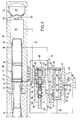
- the impact device has a working cylinder 10 in which a working piston 11 is displaceable.
- the working piston 11 strikes an anvil 12. It is provided with an annular first working surface 13 facing the anvil 12, which delimits the front cylinder space 14 of the working cylinder 10, and an oppositely directed second working surface 15, which delimits the rear cylinder space 16 of the working cylinder.
- the cylinder space 14 is sealed by seals 17 which surround the working piston 11, and the cylinder space 16 is sealed by a seal 8 which surrounds the working piston.
- the first work surface 13 is larger than that of the second work surface 15.
- the rear end of the working piston 11 facing away from the anvil 12 moves in a space 19 which is sealed off from the rear cylinder space 16 by the seal 18 and which is also sealed off from the environment.
- the rear end of the piston forms a third working surface 20 which moves in the space 19.
- the space 19 is in constant communication with a compressed gas store 21.
- the compressed gas store 21 contains a liquid space 22 and a gas space 23, which are separated from one another by a flexible membrane 24.
- the liquid space 22 communicates with the space 19.
- the compressed gas reservoir 21 is structurally combined with the working cylinder 10 or integrated into it.
- the movement of the working cylinder 11 is controlled by the control valve 25, which is connected to a pressure source 26 and is supplied via a pressure line 27.
- a further compressed gas store 28 and a pressure valve 29, which is connected to the tank 30, are connected to the pressure line 27.
- the pressure valve 29 is a pressure relief valve that connects the pressure line 27 to the tank 30 when the pressure of the pressure source 26 becomes too high.
- the control valve 25 has a control cylinder 31 in which a control piston 32 is displaceable.
- the control piston 32 has a first control surface 33 and a second control surface 34 which is opposite thereto and which is larger than the first control surface.
- the control piston 32 is provided with a through bore 35 which is constantly connected to a return line 36 leading to the tank 30.
- the through hole 35 is constantly connected to two annular grooves 37 and 38 of the control piston.
- the control surface 33 delimits an annular space 39 which is connected to the space 14 of the working cylinder 10 via a first control line 40.
- the control surface 34 delimits an annular space 70 which is connected to the pilot valve 42 via a control line 41.
- the control cylinder 31 contains an annular groove 43, which is connected via a line 44 to the space 16 of the working cylinder 10, an annular groove 74 which is permanently connected to the pressure line 27, and an annular groove 45, which is connected via a line 46 to an annular groove 47 Control cylinder 10 is connected.
- the lines 44 and 46 serve to move the control piston 11, and the control lines 40, 41 serve to move the control piston 32.
- the control piston 32 also contains an annular groove 48 which connects the annular groove 74 connected to the pressure line 27 in one position (FIG. 1) to the annular groove 43 and in the other position (FIG. 2) to the annular groove 45.
- the pilot valve 42 has a pilot cylinder 50 in which a pilot piston 51 is displaceable.
- the pilot piston 51 is hollow.
- a bore 52 leads into one end of the pilot cylinder 50 and leads to the front end of the control cylinder via a line 53 31 is connected and is continuously connected to the return line 36 via the through hole 35. Therefore, the interior of the pilot piston 51 is constantly depressurized.
- the pilot piston 51 is biased towards the one end (to the right) by a spring device 54, which here consists of a helical spring.
- the spring device 54 is supported by an abutment 55 which is axially displaceable in the pilot cylinder 50.
- the abutment 55 is connected to a screw 56 which can be rotated relative to the pilot cylinder 50 and thereby axially displaces the abutment 55 in order to adjust the preload of the spring device 54.
- the pilot cylinder 50 contains a cylinder surface 57 of larger diameter and a cylinder surface 58 of smaller diameter.
- Two annular grooves 59 and 60 are formed in the cylindrical surface 57, of which the annular groove 59 is connected to the control line 41 and of which the annular groove 60 is connected to a line 61 leading into the space 19 of the working cylinder 10. 1, the pilot cylinder 51 connects the two annular grooves 59 and 60.
- the cylinder surface 58 contains two annular grooves 62 and 63, of which the annular groove 62 is permanently connected to the line 41, while the annular groove 63 is connected to the line 53 connected and constantly depressurized.
- Line 53 is connected to line 61 via a check valve 64, which is only permeable in the direction of line 61.
- the hydraulic impact device works as follows: In Fig. 1 the beginning of the working stroke is shown. The rear end of the working piston 11 has penetrated into the space 19 and reduced its volume. As a result, liquid has been displaced from the space 19 into the compressed gas store 21, the gas contained in the space 23 having been compressed. The pressure in the space 19 is the same as in the compressed gas storage 21. This pressure is supplied via line 61 to the pilot valve 42. The pressure initially acts only in the annular groove 60 and there it presses against the first control surface 66 of the pilot piston 51. When the pressure acting on the first control surface 66 reaches an upper limit value, the pressure force exceeds the force of the spring device 54 and the pilot piston 51 becomes in the (left) end position shown in Fig. 1 pressed. In this position, the pilot piston connects the annular groove 60 to the annular groove 59, so that the pressure of the compressed gas accumulator 21 reaches the space 40 of the control valve 25 via the line 41.
- the pilot piston 42 is provided with a second working surface 67 which acts in the same direction as the working surface 66. This working surface 67 is exposed to the pressure of the annular groove 62, which is connected to the line 41 via a line 68. If the pilot piston 51 is displaced into the left end position under the effect of the pressure acting on the working surface 66, the pressure of the compressed gas reservoir 21 also acts on the second working surface 67 via line 68, so that the forces of both working surfaces 66 and 67 add up. This prevents the pilot piston 51 from leaving the end position immediately when the pressure of the compressed gas accumulator 21 drops below the upper limit.
- the pressure acting on the working surface 34 of the control piston 32 drives the control piston according to FIG. 1 into its left end position, the force acting on the working surface 33 being overcome because the surface of the working surface 34 is larger than that of the working surface 33
- Pressure line 27 is now transmitted via the ring grooves 74 and 48 to the ring groove 43 and thus via line 44 into the space 16 of the working cylinder 10.
- the space 14 of the working cylinder is depressurized.
- the stroke of the working cylinder is carried out by the pressure acting on the working surface 15 and the pressure acting on the working surface 20 with high energy.
- the compressed gas reservoir 21 discharges and the pressure prevailing in the space 19 decreases.
- control valve 25 After the control piston 32 has been switched after reaching the front end position of the working piston 11, the control valve 25 connects the annular groove 47 via the line 46 to the pressure line 27, while at the same time the space 16 is depressurized via line 44. This results in the return stroke of the working piston 11, with liquid being displaced from the space 19 into the compressed gas reservoir 21.
- the pilot piston 51 When the pressure in the compressed gas accumulator reaches the upper limit determined by the setting of the pilot valve 42, the pilot piston 51 is shifted again from the position shown in FIG. 2 to the position according to FIG. 1 under the effect of the pressure acting on the first working surface 66
- the pressure-dependent switching pilot valve 42 then effects the reversal of the control valve 25, which in turn initiates the working stroke of the working piston 11.
Landscapes
- Physics & Mathematics (AREA)
- Fluid Mechanics (AREA)
- Engineering & Computer Science (AREA)
- Mechanical Engineering (AREA)
- Fluid-Pressure Circuits (AREA)
Applications Claiming Priority (2)
| Application Number | Priority Date | Filing Date | Title |
|---|---|---|---|
| DE4229590 | 1992-09-04 | ||
| DE19924229590 DE4229590C2 (de) | 1992-09-04 | 1992-09-04 | Hydraulisches Schlaggerät mit Vorsteuerventil |
Publications (2)
| Publication Number | Publication Date |
|---|---|
| EP0587079A2 true EP0587079A2 (fr) | 1994-03-16 |
| EP0587079A3 EP0587079A3 (en) | 1994-06-08 |
Family
ID=6467248
Family Applications (1)
| Application Number | Title | Priority Date | Filing Date |
|---|---|---|---|
| EP19930114199 Withdrawn EP0587079A3 (en) | 1992-09-04 | 1993-09-04 | Hydraulic impact tool |
Country Status (2)
| Country | Link |
|---|---|
| EP (1) | EP0587079A3 (fr) |
| DE (1) | DE4229590C2 (fr) |
Cited By (3)
| Publication number | Priority date | Publication date | Assignee | Title |
|---|---|---|---|---|
| EP0827813A3 (fr) * | 1996-09-10 | 2000-04-12 | Krupp Berco Bautechnik GmbH | Dispositif hydraulique à percussion avec inversion automatique de la course du piston |
| US9308635B2 (en) | 2013-01-28 | 2016-04-12 | Caterpillar Inc. | Variable volume accumulator |
| CN114000822A (zh) * | 2021-10-23 | 2022-02-01 | 江西沃斯德凿岩液压有限公司 | 凿岩机的冲击机构 |
Families Citing this family (3)
| Publication number | Priority date | Publication date | Assignee | Title |
|---|---|---|---|---|
| DE10003415B4 (de) * | 2000-01-27 | 2005-06-16 | Carl Freudenberg Kg | Hydraulikhammer mit einem Druckgasspeicher |
| JP7210452B2 (ja) * | 2017-07-24 | 2023-01-23 | 古河ロックドリル株式会社 | 液圧式打撃装置 |
| CN108547822B (zh) * | 2018-05-18 | 2020-08-18 | 蠡县虓志燃气有限公司 | 一种用于天然气压缩站的自动换向阀 |
Family Cites Families (3)
| Publication number | Priority date | Publication date | Assignee | Title |
|---|---|---|---|---|
| GB1356022A (en) * | 1971-02-10 | 1974-06-12 | Dobson Park Ind | Impact tools or apparatus |
| DE2461633C2 (de) * | 1974-12-27 | 1982-05-06 | Ing. Günter Klemm, Spezialunternehmen für Bohrtechnik, 5962 Drolshagen | Hydraulische Schlagvorrichtung |
| FI72908C (fi) * | 1979-06-29 | 1987-08-10 | Rammer Oy | Hydraulisk slagmaskin. |
-
1992
- 1992-09-04 DE DE19924229590 patent/DE4229590C2/de not_active Expired - Fee Related
-
1993
- 1993-09-04 EP EP19930114199 patent/EP0587079A3/de not_active Withdrawn
Cited By (3)
| Publication number | Priority date | Publication date | Assignee | Title |
|---|---|---|---|---|
| EP0827813A3 (fr) * | 1996-09-10 | 2000-04-12 | Krupp Berco Bautechnik GmbH | Dispositif hydraulique à percussion avec inversion automatique de la course du piston |
| US9308635B2 (en) | 2013-01-28 | 2016-04-12 | Caterpillar Inc. | Variable volume accumulator |
| CN114000822A (zh) * | 2021-10-23 | 2022-02-01 | 江西沃斯德凿岩液压有限公司 | 凿岩机的冲击机构 |
Also Published As
| Publication number | Publication date |
|---|---|
| DE4229590A1 (de) | 1994-03-10 |
| DE4229590C2 (de) | 1996-06-20 |
| EP0587079A3 (en) | 1994-06-08 |
Similar Documents
| Publication | Publication Date | Title |
|---|---|---|
| DE2635191C3 (de) | Hydraulische Gesteins-Schlagbohrmaschine | |
| EP0283734B1 (fr) | Appareil de forage à percussion à tête de frappe mobile | |
| DE2512731C2 (fr) | ||
| DE2707790A1 (de) | Vorrichtung zum uebertragen von schlaegen auf ein langgestrecktes bauelement | |
| DE102017005548B4 (de) | Bohrkopf | |
| DE3882971T3 (de) | Hydraulische Schlagvorrichtung. | |
| DE3518892C1 (de) | Hydraulische Schlagbohrvorrichtung | |
| EP0273139B1 (fr) | Mouton de forage | |
| DE2147935B2 (de) | Schlagwerkzeug | |
| DE4229590C2 (de) | Hydraulisches Schlaggerät mit Vorsteuerventil | |
| DE2461633C2 (de) | Hydraulische Schlagvorrichtung | |
| DE3523219C1 (de) | Hydraulischer Bagger | |
| EP0672506B1 (fr) | Marteau à percussion hydraulique | |
| CH633989A5 (de) | Vorrichtung zum eintreiben von bolzen und naegeln mittels druckluft. | |
| EP0441172A2 (fr) | Mouton de forage | |
| DE2107510B2 (de) | Hydraulisches schlagwerkzeug | |
| DE19545708A1 (de) | Verfahren zur Beeinflussung des Betriebsverhaltens eines fluidbetriebenen Schlagwerks und zur Durchführung des Verfahrens geeignetes Schlagwerk | |
| DE3590888C2 (de) | Stossvorrichtung | |
| DE2360821C3 (de) | Steuereinrichtung für hydraulische Pressen mit mehreren Presskolben | |
| CH621731A5 (fr) | ||
| DE2346519A1 (de) | Hydraulisch betriebene schlagvorrichtung | |
| CH689872A5 (de) | Hydraulischer Schlaghammer. | |
| DE4424080C1 (de) | Hydraulischer Schlaghammer | |
| DE102014011403A1 (de) | Rammbohrgerät | |
| DE1243118B (de) | Steuerung fuer hydraulisch betriebene Schlagvorrichtungen, insbesondere fuer handgefuehrte Schlagwerkzeuge mit in einer Fuehrung laengsverschieblich gelagertem Einsteckwerkzeug |
Legal Events
| Date | Code | Title | Description |
|---|---|---|---|
| PUAI | Public reference made under article 153(3) epc to a published international application that has entered the european phase |
Free format text: ORIGINAL CODE: 0009012 |
|
| AK | Designated contracting states |
Kind code of ref document: A2 Designated state(s): AT CH DE ES FR GB IT LI NL |
|
| PUAL | Search report despatched |
Free format text: ORIGINAL CODE: 0009013 |
|
| AK | Designated contracting states |
Kind code of ref document: A3 Designated state(s): AT CH DE ES FR GB IT LI NL |
|
| 17P | Request for examination filed |
Effective date: 19941125 |
|
| 17Q | First examination report despatched |
Effective date: 19960222 |
|
| 18D | Application deemed to be withdrawn |
Effective date: 19960703 |