EP0587185A2 - Kontinuierliche Dispergiervorrichtung - Google Patents
Kontinuierliche Dispergiervorrichtung Download PDFInfo
- Publication number
- EP0587185A2 EP0587185A2 EP19930114601 EP93114601A EP0587185A2 EP 0587185 A2 EP0587185 A2 EP 0587185A2 EP 19930114601 EP19930114601 EP 19930114601 EP 93114601 A EP93114601 A EP 93114601A EP 0587185 A2 EP0587185 A2 EP 0587185A2
- Authority
- EP
- European Patent Office
- Prior art keywords
- vessel
- dispersing apparatus
- rotating shaft
- continuous dispersing
- chambers
- Prior art date
- Legal status (The legal status is an assumption and is not a legal conclusion. Google has not performed a legal analysis and makes no representation as to the accuracy of the status listed.)
- Granted
Links
Images

Classifications
-
- B—PERFORMING OPERATIONS; TRANSPORTING
- B02—CRUSHING, PULVERISING, OR DISINTEGRATING; PREPARATORY TREATMENT OF GRAIN FOR MILLING
- B02C—CRUSHING, PULVERISING, OR DISINTEGRATING IN GENERAL; MILLING GRAIN
- B02C17/00—Disintegrating by tumbling mills, i.e. mills having a container charged with the material to be disintegrated with or without special disintegrating members such as pebbles or balls
- B02C17/16—Mills in which a fixed container houses stirring means tumbling the charge
-
- B—PERFORMING OPERATIONS; TRANSPORTING
- B01—PHYSICAL OR CHEMICAL PROCESSES OR APPARATUS IN GENERAL
- B01F—MIXING, e.g. DISSOLVING, EMULSIFYING OR DISPERSING
- B01F27/00—Mixers with rotary stirring devices in fixed receptacles; Kneaders
- B01F27/60—Mixers with rotary stirring devices in fixed receptacles; Kneaders with stirrers rotating about a horizontal or inclined axis
-
- B—PERFORMING OPERATIONS; TRANSPORTING
- B01—PHYSICAL OR CHEMICAL PROCESSES OR APPARATUS IN GENERAL
- B01F—MIXING, e.g. DISSOLVING, EMULSIFYING OR DISPERSING
- B01F33/00—Other mixers; Mixing plants; Combinations of mixers
- B01F33/25—Mixers with loose mixing elements, e.g. loose balls in a receptacle
- B01F33/251—Mixers with loose mixing elements, e.g. loose balls in a receptacle using balls as loose mixing element
Definitions
- the invention relates to a continuous dispersing apparatus in which stirring vanes in a vessel disperse pulverized media.
- a mill base which is formed by dispersing a powdered pigment in a varnish, a solvent or the like at a high concentration.
- a powdered pigment composed of secondary particles formed by agglutinating primary particles of the pigment is pulverized and dispersed in a varnish to produce fine particles not containing coarse particles. Such process is employed to improve the tinting strength of the printing ink and the paint.
- Dispersing apparatuses such as a sand mill, a grain mill, a ball mill and the like are known.
- Dispersing apparatuses capable of preparing printing ink, etc. continuously are designed to continuously supply a mill base material from a material supply inlet that communicates with a vessel, a dispersing process is performed in the vessel, and thereafter the dispersed mill base is discharged continuously from a discharge outlet.
- the supplied mill base material is not dispersed uniformly in the vessel, so-called "short-pass" occurs whereby mill base containing coarse pigment particles is discharged from the discharge outlet.
- the problem of short pass can be prevented to a certain degree by increasing the rate of loading of pulverized media.
- too high a rate of loading of the media induces choking, which results in an uneven distribution of the media on the discharge outlet side, thereby leading to unstable operation of the apparatus.
- the apparatus is operated at a rate of loading of the pulverized media of about 75 to 80%.
- an object of the invention is to provide an economically advantageous continuous dispersing apparatus with high pulverizing and dispersing efficiency.
- the invention is applied to a continuous dispersing apparatus that comprises a vessel for containing pulverized media; a supply inlet and a discharge outlet formed at respective ends of the vessel, a rotating disc mounted on a rotating shaft passing through the vessel, a partition defining a gap which prevents the passage of the pulverized media while passing dispersed material, wherein the partition divides the vessel into a plurality of chambers, each chamber having at least one stirring means mounted on the rotating shaft.
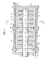
- a continuous dispersing apparatus of the invention has a vessel 10 and a rotating shaft 15 that passes through the vessel 10 via at least one end surface of the vessel 10. While a cylindrical-shaped vessel 10 is shown in the drawings, the section of the vessel may be rectangular, hexagonal, octagonal, or conical. While the capacity of the vessel depends on the size of pulverized media 20, a capacity of 0.5 liters or more may be practically usable.
- Stirring vanes 16 formed by a plurality of coaxially mounted pins are mounted on the rotating shaft 15. While the pin may be circular in section, it may also take other sectional forms such as a rectangular, hexagonal, or octagonal.
- the stirring vane 16 may be formed of a pair of pins mounted in symmetrical form, or four to eight pins may be mounted coaxially in symmetrical form.
- the stirring vane 16 may also be a flat disc or conical disc having holes such as to allow the pulverized media 20 to pass therethrough.
- the distance between the top of the stirring vane 16 and the inner surface of the vessel 10 is preferably at least three times the diameter of the pulverized media.
- the inside of the rotating shaft 15 is a cooling water path 15a so that cooling water can circulate therethrough.
- the rotating shaft is rotated by a rotational power source (not shown) at a peripheral speed of 8 to 12 m/sec.
- the outside of the vessel 10 is a cooling water flow path 17.
- the pulverized media 20 are made of spherical, flat, or amorphous steel, ceramic, stone, or the like.
- a spherical medium may have an average grain size of 0.3 to 3 mm.
- the rate of loading of the pulverized media 20 is from 70 to 95%, or preferably from 85 to 90%.
- a partition 13 includes a rotating disc 13a mounted on the rotating shaft 15, and a ring-like plate 13b fixed to the inner wall of the vessel 10.
- a slit-like gap 14 is formed between the disc 13a and the plate 13b.
- the width of the slit does not allow a dispersed material to pass therethrough, but allows the pulverized media 20 to pass therethrough. If the average size of a spherical pulverized medium 20 is 1.5 mm, the width of the slit is set to about 0.3 to 0.4 mm.
- the vessel 10 is divided into a first chamber 10a and a second chamber 10b by the partition 13. While two chambers are formed by the partition 13 as shown in Fig. 1, the number of chambers may be larger than two. It is preferable to arrange two to six stirring vanes along the length of the rotating shaft 15 in each chamber.
- the gap 14 may be slit-like, or may be in the form of a plurality of small holes.
- the gap 14 is preferably formed close to the inner wall of the vessel 10. The reason for this is as follows. When the rotating vanes 16 rotate, the pulverized media 20 are distributed in the vicinity of the inner wall of the vessel 10 by centrifugal force. Therefore, while the material to be dispersed which is near the vessel 10 is distributed by the pulverized media 20 efficiently, the material to be dispersed which is near the rotating shaft 15 is dispersed poorly. Thus, the material that has been dispersed satisfactorily must be transferred to the next chamber efficiently.
- the partition 13 includes the disc 13a releasably fixed to the rotating shaft 15 and the ring-like plate 13b fixed to the inner wall of the vessel.
- the radius of the disc 13a is larger than the radius of gyration of the stirring vane 16 so that a dispersing apparatus can be obtained which is easy to disassemble and maintain.
- a material supply inlet 11 for supplying the material to be dispersed is formed at one end of the vessel 10, when the material comprises a powder pigment and a varnish or a solvent or the like, so that the material can be supplied continuously from the material supply inlet 11.
- the material dispersed in the chambers 10a and 10b of the vessel 10 is designed to be discharged continuously from a discharge outlet 12 through a slit 19 of a partition 18 that is of the same design as the partition 13.
- Pulverized media of varying grain sizes may be loaded into the respective chambers in the dispersing apparatus of the invention. That is, pulverized media having a relatively large grain size may be loaded in the first chamber, and pulverized media having a smaller grain size loaded in the next chamber. Such an arrangement contributes to efficient dispersing.
- the conventional dispersing apparatus is designed so that its vessel is formed of a single chamber, the pulverized media are subjected to density distribution by the centrifugal force of the rotating vanes so as to cause the material dispersed by the pulverized media of small density to be discharged from the discharge outlet as insufficiently dispersed.
- the vessel is divided into two or more chambers. Therefore, the material to be dispersed undergoes a pulverizing and dispersing process in the first chamber, and only the dispersed material is allowed to pass through the partition thereafter so that the transfer distance of the dispersed material is long, is pulverized and dispersed sufficiently.
- the conventional continuous dispersing apparatus supplies the material to be dispersed continuously, a stream of the dispersed material is produced within the vessel, thereby tending to distribute the pulverized media locally on the discharge outlet side by the transfer force.
- the invention which is characterized by dividing the vessel by the partition, such a disadvantage is reduced.
- the conventional upper limit of the rate of loading of the pulverized media which is about 85%, can be improved to about 90% or more by the dispersing apparatus of the invention.
- the invention can improve the productivity of producing a printing ink mill basis by about 50% over the productivity of the conventional dispersing apparatus of the same capacity.
Landscapes
- Chemical & Material Sciences (AREA)
- Chemical Kinetics & Catalysis (AREA)
- Engineering & Computer Science (AREA)
- Food Science & Technology (AREA)
- Mixers Of The Rotary Stirring Type (AREA)
- Crushing And Grinding (AREA)
Applications Claiming Priority (4)
| Application Number | Priority Date | Filing Date | Title |
|---|---|---|---|
| JP26940192 | 1992-09-11 | ||
| JP269401/92 | 1992-09-11 | ||
| JP5058829A JPH06134271A (ja) | 1992-09-11 | 1993-03-18 | 連続式分散装置 |
| JP58829/93 | 1993-03-18 |
Publications (3)
| Publication Number | Publication Date |
|---|---|
| EP0587185A2 true EP0587185A2 (de) | 1994-03-16 |
| EP0587185A3 EP0587185A3 (en) | 1994-09-28 |
| EP0587185B1 EP0587185B1 (de) | 1997-07-02 |
Family
ID=26399838
Family Applications (1)
| Application Number | Title | Priority Date | Filing Date |
|---|---|---|---|
| EP93114601A Expired - Lifetime EP0587185B1 (de) | 1992-09-11 | 1993-09-10 | Kontinuierliche Dispergiervorrichtung |
Country Status (3)
| Country | Link |
|---|---|
| EP (1) | EP0587185B1 (de) |
| JP (1) | JPH06134271A (de) |
| DE (1) | DE69311862T2 (de) |
Cited By (6)
| Publication number | Priority date | Publication date | Assignee | Title |
|---|---|---|---|---|
| WO1998022220A1 (en) * | 1996-11-22 | 1998-05-28 | Toyo Ink Manufacturing Co., Ltd. | Dispersing apparatus |
| CN106310989A (zh) * | 2016-11-18 | 2017-01-11 | 安陆鲸鱼嘴电子科技有限公司 | 一种便于乳膏剂出料的乳化设备 |
| CN108176306A (zh) * | 2018-01-05 | 2018-06-19 | 刘楚楚 | 一种油漆密闭搅拌设备 |
| CN112024058A (zh) * | 2020-09-16 | 2020-12-04 | 郴州市东卓矿山设备有限公司 | 干式磨机 |
| CN112535976A (zh) * | 2020-11-17 | 2021-03-23 | 湖南省方圆磨料磨具有限公司 | 一种制造砂轮用的混料设备 |
| CN112755843A (zh) * | 2020-12-24 | 2021-05-07 | 广东赛安特新材料有限公司 | 一种搅拌乳化设备 |
Families Citing this family (6)
| Publication number | Priority date | Publication date | Assignee | Title |
|---|---|---|---|---|
| JP2002204969A (ja) * | 2001-01-10 | 2002-07-23 | Inoue Seisakusho:Kk | パイプラインビ−ズミル |
| JP2007229578A (ja) * | 2006-02-28 | 2007-09-13 | Toray Ind Inc | ペースト分散装置およびペーストの製造方法 |
| KR100921190B1 (ko) * | 2009-02-25 | 2009-10-13 | 베스트화학기계공업(주) | 그라인딩 효율성을 개선한 탑 밀 |
| CN107755018A (zh) * | 2017-11-23 | 2018-03-06 | 恩平市弘彩数码科技有限公司 | 一种纳米研磨机缝隙分离器 |
| KR102663295B1 (ko) * | 2021-09-27 | 2024-05-29 | 주식회사 이앤에이치 | 입자 이동 부재를 포함하는 나노 버블 발생기 |
| GB2634870A (en) * | 2023-10-12 | 2025-04-30 | Wortley Anthony | A nanobubble generator and a method of generating nanobubbles |
Family Cites Families (7)
| Publication number | Priority date | Publication date | Assignee | Title |
|---|---|---|---|---|
| US3149789A (en) * | 1960-10-28 | 1964-09-22 | Szegvari Andrew | Continuous process of grinding particulate material |
| US3698647A (en) * | 1970-12-08 | 1972-10-17 | Ferrox Iron Ltd | Process for grinding particulate solids |
| US4106116A (en) * | 1977-01-07 | 1978-08-08 | Mackay Malcolm H | Dispersing apparatus |
| JPS5946663B2 (ja) * | 1982-03-08 | 1984-11-14 | 大日本塗料株式会社 | 練合分散機 |
| JPS5946664B2 (ja) * | 1982-03-24 | 1984-11-14 | 大日本塗料株式会社 | 練合分散機 |
| AU1097583A (en) * | 1983-02-03 | 1984-08-09 | Union Process International Inc. | Comminuting mill |
| DE3431553A1 (de) * | 1984-08-28 | 1986-03-13 | Draiswerke Gmbh, 6800 Mannheim | Ruehrwerksmuehle |
-
1993
- 1993-03-18 JP JP5058829A patent/JPH06134271A/ja active Pending
- 1993-09-10 DE DE69311862T patent/DE69311862T2/de not_active Expired - Fee Related
- 1993-09-10 EP EP93114601A patent/EP0587185B1/de not_active Expired - Lifetime
Cited By (7)
| Publication number | Priority date | Publication date | Assignee | Title |
|---|---|---|---|---|
| WO1998022220A1 (en) * | 1996-11-22 | 1998-05-28 | Toyo Ink Manufacturing Co., Ltd. | Dispersing apparatus |
| US6029920A (en) * | 1996-11-22 | 2000-02-29 | Toyo Ink Manufacturing Co., Ltd. | Dispersing apparatus |
| CN106310989A (zh) * | 2016-11-18 | 2017-01-11 | 安陆鲸鱼嘴电子科技有限公司 | 一种便于乳膏剂出料的乳化设备 |
| CN108176306A (zh) * | 2018-01-05 | 2018-06-19 | 刘楚楚 | 一种油漆密闭搅拌设备 |
| CN112024058A (zh) * | 2020-09-16 | 2020-12-04 | 郴州市东卓矿山设备有限公司 | 干式磨机 |
| CN112535976A (zh) * | 2020-11-17 | 2021-03-23 | 湖南省方圆磨料磨具有限公司 | 一种制造砂轮用的混料设备 |
| CN112755843A (zh) * | 2020-12-24 | 2021-05-07 | 广东赛安特新材料有限公司 | 一种搅拌乳化设备 |
Also Published As
| Publication number | Publication date |
|---|---|
| EP0587185A3 (en) | 1994-09-28 |
| EP0587185B1 (de) | 1997-07-02 |
| DE69311862D1 (de) | 1997-08-07 |
| JPH06134271A (ja) | 1994-05-17 |
| DE69311862T2 (de) | 1998-01-02 |
Similar Documents
| Publication | Publication Date | Title |
|---|---|---|
| EP0587185A2 (de) | Kontinuierliche Dispergiervorrichtung | |
| US4979686A (en) | High speed dry grinder | |
| US6789756B2 (en) | Vortex mill for controlled milling of particulate solids | |
| US3559895A (en) | Apparatus for and method of comminuting solid materials | |
| JPS6243731B2 (de) | ||
| US7883041B2 (en) | Media mixing mill | |
| JP3095937B2 (ja) | 流動層噴流粉砕法および流動層噴流粉砕装置 | |
| KR20130118886A (ko) | 교반 볼 분쇄기 | |
| EP0129384A2 (de) | Rotorscheiben für Sandmühle | |
| JP2000237563A (ja) | 連続式分散装置 | |
| EP0379588B1 (de) | Vorrichtung und verfahren zum mahlen und pulverisieren | |
| US6029920A (en) | Dispersing apparatus | |
| US7455252B2 (en) | Powder particle disintegrating and sizing apparatus | |
| US5524830A (en) | Continuous dispersing apparatus | |
| JP2003144950A (ja) | 粉砕機 | |
| JPH02303560A (ja) | 微粉用空気分級機 | |
| CA1256414A (en) | Vertical grinding mill | |
| CN1136472A (zh) | 分散研磨机 | |
| JPH04193360A (ja) | 乾式媒体ミル | |
| JPH11114439A (ja) | 粉砕機 | |
| JPH0910611A (ja) | 分散機 | |
| JP3084026B1 (ja) | 縦型撹拌乾燥装置 | |
| JPH08318145A (ja) | 連続式分散装置 | |
| JPH06218296A (ja) | 攪拌ミルを有する粉砕装置 | |
| JPH09103665A (ja) | 分散装置 |
Legal Events
| Date | Code | Title | Description |
|---|---|---|---|
| PUAI | Public reference made under article 153(3) epc to a published international application that has entered the european phase |
Free format text: ORIGINAL CODE: 0009012 |
|
| AK | Designated contracting states |
Kind code of ref document: A2 Designated state(s): DE FR GB |
|
| RIN1 | Information on inventor provided before grant (corrected) |
Inventor name: KANAI, KOUICHI C/O TOYO INK MANUFACTURING CO. LTD Inventor name: YOSHIDA, FUMIO C/O TOYO INK MANUFACTURING CO. LTD Inventor name: MIZOGUCHI, NAOJI C/O TOYO INK MANUFACTURING CO.LT Inventor name: MURASE, YASUHIKO C/O TOYO INK MANUFACTURING CO.LTD |
|
| PUAL | Search report despatched |
Free format text: ORIGINAL CODE: 0009013 |
|
| AK | Designated contracting states |
Kind code of ref document: A3 Designated state(s): DE FR GB |
|
| 17P | Request for examination filed |
Effective date: 19941115 |
|
| 17Q | First examination report despatched |
Effective date: 19951220 |
|
| GRAG | Despatch of communication of intention to grant |
Free format text: ORIGINAL CODE: EPIDOS AGRA |
|
| GRAH | Despatch of communication of intention to grant a patent |
Free format text: ORIGINAL CODE: EPIDOS IGRA |
|
| GRAH | Despatch of communication of intention to grant a patent |
Free format text: ORIGINAL CODE: EPIDOS IGRA |
|
| GRAA | (expected) grant |
Free format text: ORIGINAL CODE: 0009210 |
|
| AK | Designated contracting states |
Kind code of ref document: B1 Designated state(s): DE FR GB |
|
| REF | Corresponds to: |
Ref document number: 69311862 Country of ref document: DE Date of ref document: 19970807 |
|
| ET | Fr: translation filed | ||
| PLBE | No opposition filed within time limit |
Free format text: ORIGINAL CODE: 0009261 |
|
| 26N | No opposition filed | ||
| REG | Reference to a national code |
Ref country code: GB Ref legal event code: IF02 |
|
| PGFP | Annual fee paid to national office [announced via postgrant information from national office to epo] |
Ref country code: DE Payment date: 20070906 Year of fee payment: 15 |
|
| PGFP | Annual fee paid to national office [announced via postgrant information from national office to epo] |
Ref country code: GB Payment date: 20070905 Year of fee payment: 15 |
|
| PGFP | Annual fee paid to national office [announced via postgrant information from national office to epo] |
Ref country code: FR Payment date: 20070914 Year of fee payment: 15 |
|
| GBPC | Gb: european patent ceased through non-payment of renewal fee |
Effective date: 20080910 |
|
| REG | Reference to a national code |
Ref country code: FR Ref legal event code: ST Effective date: 20090529 |
|
| PG25 | Lapsed in a contracting state [announced via postgrant information from national office to epo] |
Ref country code: DE Free format text: LAPSE BECAUSE OF NON-PAYMENT OF DUE FEES Effective date: 20090401 |
|
| PG25 | Lapsed in a contracting state [announced via postgrant information from national office to epo] |
Ref country code: FR Free format text: LAPSE BECAUSE OF NON-PAYMENT OF DUE FEES Effective date: 20080930 |
|
| PG25 | Lapsed in a contracting state [announced via postgrant information from national office to epo] |
Ref country code: GB Free format text: LAPSE BECAUSE OF NON-PAYMENT OF DUE FEES Effective date: 20080910 |