EP0587363A2 - Condenseur pour turbine à vapeur et méthode d'opération d'un tel condenseur - Google Patents
Condenseur pour turbine à vapeur et méthode d'opération d'un tel condenseur Download PDFInfo
- Publication number
- EP0587363A2 EP0587363A2 EP93306870A EP93306870A EP0587363A2 EP 0587363 A2 EP0587363 A2 EP 0587363A2 EP 93306870 A EP93306870 A EP 93306870A EP 93306870 A EP93306870 A EP 93306870A EP 0587363 A2 EP0587363 A2 EP 0587363A2
- Authority
- EP
- European Patent Office
- Prior art keywords
- condenser
- steam
- drain
- condensate
- tube bundle
- Prior art date
- Legal status (The legal status is an assumption and is not a legal conclusion. Google has not performed a legal analysis and makes no representation as to the accuracy of the status listed.)
- Granted
Links
Images


Classifications
-
- F—MECHANICAL ENGINEERING; LIGHTING; HEATING; WEAPONS; BLASTING
- F28—HEAT EXCHANGE IN GENERAL
- F28B—STEAM OR VAPOUR CONDENSERS
- F28B9/00—Auxiliary systems, arrangements, or devices
- F28B9/08—Auxiliary systems, arrangements, or devices for collecting and removing condensate
-
- F—MECHANICAL ENGINEERING; LIGHTING; HEATING; WEAPONS; BLASTING
- F01—MACHINES OR ENGINES IN GENERAL; ENGINE PLANTS IN GENERAL; STEAM ENGINES
- F01K—STEAM ENGINE PLANTS; STEAM ACCUMULATORS; ENGINE PLANTS NOT OTHERWISE PROVIDED FOR; ENGINES USING SPECIAL WORKING FLUIDS OR CYCLES
- F01K9/00—Plants characterised by condensers arranged or modified to co-operate with the engines
Definitions
- This invention relates to a method of operating a main steam condenser of a steam turbine which is driven by steam from a boiler.
- the condensate in the main condenser is fed to the boiler.
- the invention also relates to a condenser for condensing the driving steam of such a turbine.
- a main steam condenser having an isolatable condenser hot well unit is known from JP-A-2-95704 and is illustrated in Fig. 8 accompanying this application.
- This condenser includes a tube bundle 28 in a tube bundle unit 2 comprising condensing tubes for cooling and condensing the steam turbine exhaust steam with sea water or the like, and a hot well unit 3 for storing the condensate, isolated by a condenser partition 7 having a shut-off valve 4.
- the shut-off valve 4 disposed in the partition 7 is opened in normal running so that the water condensed in the tube bundle unit is stored in the hot well unit until it is fed to the boiler.
- the shut-off valve 4 When the operation of the condenser is interrupted, the shut-off valve 4 is closed to leave only the tube bundle unit 2 opened to the atmosphere so that the condensate in the hot well unit is prevented from having its quality deteriorated by oxygen or the like dissolved therein during the interruption.
- the drain stored in the tube bundle unit during the interruption is discharged to outside via a drain pipe 9 having a valve 10 and the vacuum in the tube bundle unit is raised by an air extractor 17 in line 18.
- the shut-off valve 4 is opened to connect the tube bundle unit 2 and the hot well unit 3 when their pressures are substantially equalized to each other.
- the partition-type condenser of this construction is being widely adopted in a combined cycle plant for the DSS operation (daily start-stop) in which it is started and stopped every day so that it may be used a daytime power source.
- the plant can be started for a short time and with economy of power.
- the drain accumulated on the condenser partition 7 while the condenser operation is interrupted can be discharged to the outside of the condenser, but no consideration is made for the treatment of the drain which is generated at the start-up of the plant.
- the drain generated during the stop period when the condenser is opened to the atmosphere contains much oxygen, so that it cannot be mixed with the condensate in the hot well unit. Therefore, it is correct to discharge this drain which is accumulated on the condenser partition during the stop period of the condenser, to the outside of the condenser.
- the drain generated at the initial stage of the plant start-up has low quality, but in a later period has a high quality. Thus, it is effective for economical plant running to recover those two kinds of drains to the condenser, but this has not been considered in the prior art.
- the drain accumulated in the condenser tube bundle unit 2 at the start may be mixed directly into the hot well unit 3 by opening the shut-off valve at an early stage after the start.
- the drain at this stage contains much oxygen, the quality of the condensate water after the mixing highly departs from the.required value for the boiler supply water so that hot well condensate 29 has to be de-aerated.
- gland seal steam discharged from the steam gland may be condensed in a gland steam condenser 15 shown in the prior art example of Fig. 8. Steam is fed to this condenser 15 via line 21.
- the heat exchange is effected in condenser 15 by main steam condensate from the hot well 3, which may be recirculated directly to the hot well via line 16.
- the destination of gland steam condensate from the condenser 15 is not mentioned.
- JP-A-4-112903 shows a turbine steam condenser system in which the gland steam condensate is returned directly into the hot well. There is no partition in this case between the hot well and the tube bundle unit. This method is disadvantageous.
- the present inventors have now appreciated that initially at start-up of the turbine, the gland steam has a high oxygen content, so that its condensate is unsuitable to be fed into the main steam condensate, for re-feeding to the boiler.
- US-A-5095706 shows a partition between the hot well and the tube bundle unit, like JP-A-2-95704.
- An object of the present invention is to provide a condenser for a steam turbine and a method of its operation, which make it possible to run the plant economically and to minimize the time period for starting the condenser while recovering the drain to the condenser at start-up.
- Another object of the invention is to make it possible to recover, at least partly, the gland seal steam, without deteriorating the quality of the circulating water.
- a method of operating a main steam condenser of a steam turbine driven by a boiler and having a gland steam condenser in which, after start-up of the turbine, the gland steam condensate is fed from said gland steam condenser into the main condenser condensate.
- the method is characterized by the step of, for at least part of the start-up period of the turbine, preventing the gland steam condensate from entering the main condenser condensate to be fed to the boiler. In this way deterioration of the quality of the main condensate is avoided or minimized during start-up.
- the gland steam condensate may be discharged from the circulating flows of water, i.e. outside the condenser system.
- the gland steam condensate is fed to the main condenser and stored in a reservoir thereof separate from the hot well, and undergoes de-aeration before being fed into the main condenser condensate to be fed to the boiler.
- the invention provides a method of operating a main condenser of a steam turbine driven by steam from a boiler, which main condenser has a tube bundle and a hot well, comprising the steps of:
- the drain having a relatively high oxygen content in the de-aeration region may be de-aerated by maintaining the de-aeration region at substantially the same pressure as a space containing the tube bundle.
- the drain having a relatively high oxygen content may be at least partly condensate from a gland steam condenser.
- the invention also provides a method of operating a main condenser of a steam turbine driven by steam from a boiler and having a gland steam condenser, the main condenser having a tube bundle for condensation of steam from the steam turbine and a hot well for accumulation of drain from said tube bundle, in which condensate from the gland steam condenser is fed to the main condenser.
- the method is characterized by the step of, during a start-up period of the turbine, storing the condensate from the gland steam condenser in a reservoir separated from the hot well, until the oxygen content of said condensate flowing from the gland steam condenser has fallen below a predetermined level.
- the invention provides a condenser for condensing the driving steam of a steam turbine, having:
- the latter means (f) for selectively establishing flow and pressure isolating preferably comprises a conduit for flow of drain from the drain region to the hot well by-passing the reservoir and valve means for closing the conduit.
- the reservoir is preferably arranged above the hot well and separated from the drain region by a partition.
- the reservoir is preferably connected to the drain region by an air flow passage for maintaining the reservoir and the drain region at substantially equal pressures.
- the condenser For re-introducing the drain in the reservoir to the circulatory flow, the condenser preferably has a conduit for flow of drain from the reservoir to the hot well and valve means for controlling flow therein. Alternatively, means are provided for controlledly feeding a flow of drain from the reservoir to the steam generator.
- the invention also provides a condenser for condensing the driving steam of a steam turbine, having:
- the invention can provide a condenser for a steam turbine having a main steam condenser for condensing driving steam of the turbine, a gland steam condenser for condensing gland steam from a steam gland of the turbine, and means for selectively (i) feeding steam condensate from the gland steam condenser into the main condenser condensate and (ii) preventing gland steam condensate from entering the main condenser condensate.
- the invention further provides a condenser for a steam turbine driven by steam from a boiler, which condenser has a tube bundle for condensation of driving steam of the turbine, a drain region below the tube bundle, a hot well for accumulation of condensate from the tube bundle, a de-aeration region separated from the hot well for storing a body of drain formed by condensation of steam, means for establishing a flow of drain from the tube bundle to the hot well by-passing the de-aeration region, and means for feeding the body of drain from the de-aeration region to one of said hot well and said boiler.
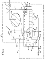
- the turbine exhaust steam is introduced from the steam turbine (not shown) via an exhaust conduit (not shown) into a main steam condenser 1 from above and is cooled and condensed into condensate by sea water in a cooling tube bundle 28.
- the condensate is stored, in an amount corresponding to about five minutes of its rated flow rate considering load fluctuations, in a hot well 29 and is fed by a condensed water feeder 13 through a boiler water supply line 14, a gland steam condenser 15 and a change-over valve 26 to a steam generator such as a waste heat recovery boiler HRSG.
- the steam generated by this steam generator is fed to the aforementioned turbine. In ordinary or normal running mode, the steam and the water circulate by this route.
- the main condenser 1 is partitioned into a tube bundle unit 2 and a hot well unit 3 by means of a partition 7, and these are connected by a down-comer 6 having a shut-off unit or valve 4.
- the shut-off unit 4 is closed, when the plant is to be stopped, so that the vacuum in the tube bundle unit 2 can be broken to stop the plant while the hot well unit 3 is kept under vacuum.
- the hot well unit 3 is kept out of contact with the air during a stop period so that the hot well 29 keeps the condensate in a satisfactory quality for the running operation.
- a drain shut-off valve 10 is left open, and the drain present in the tube bundle unit 2 during the stop is discharged from above the partition 7 via a drain pipe 9.
- cooling water is fed first into the cooling tube bundle 28 by a cooling water feeder (not shown).
- the vacuum in the condenser 1 is then established.
- a turbine steam gland unit (not shown) must be sealed to prevent ambient air from flowing into the condenser 1 via the turbine gland.
- gland seal steam passing from the turbine gland is introduced via a gland steam line 21 into the gland steam condenser 15 so that the gland seal steam is cooled and condensed.
- the condensate water reserved in the condenser hot well 29 is used for cooling and condensing in the gland steam condenser 15.
- the turbine gland unit After the start of the gland steam condenser 15, the turbine gland unit can thus be sealed by feeding the gland seal steam to the turbine gland unit.
- the condensate used for the cooling and condensation in the gland steam condenser 15 is not fed to the HRSG in the preparation for starting the HRSG but is recirculated to the condenser 1 through a condensate recirculation line 16. This is because, if the HRSG is fed with this water, the amount of water in the condenser hot well 29 decreases with the consequence that supply water which is oxygen-rich is fed to the condenser 1 to maintain the water level. This water supply during the start-up would deteriorate the quality of the condensed water, elongating the start-up period. Therefore, the change-over valve 26 is closed and the change-over valve 27 is opened to recirculate the condensate directly to the hot well unit 3 of the condenser 1 thereby to continue the water supply to the cooling tubes in the gland steam condenser 15.
- the condensate in the tube bundle unit 2 is introduced into the hot well unit 3 by some means, the vacuum in the hot well unit 3 is broken, allowing oxygen to dissolve in the condensate in the hot well 29, deteriorating the quality of the condensate. Therefore, in the condenser 1 in which the good quality condensate satisfying water quality requirements is reserved in the hot well 29 by shutting off the hot well in order to shorten the start-up time the next day and to save auxiliary power required for the start-up, it is very advantageous to introduce this recirculated condensate directly into the hot well unit 3.
- a combined cycle plant for the DSS run has a simple system construction and easy control because the amount of drain generated in the plant system is smaller than that of the conventional fossil fuel plant.
- this drain is introduced via a change-over valve 24 and a drain recovery line 22 into the tube bundle unit 2 of the condenser 1 by making use of the pressure difference and the head difference but no power, and is discharged by gravity to the outside of the condenser 1 via the drain pipe 9 branching from the down-comer 6 and the drain shut-off valve 10.
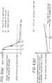
- Fig. 6(a) plots the oxygen concentration of this drain from the gland steam condenser introduced into the condenser 1 during the start-up.
- the drain concentration is about 10,000 (ppb) just after the start.
- an air extractor for the condenser 1 operates (see below) after the start, the oxygen concentration falls to the rated reference value of 7 (ppb) before long.
- the drain introduced into the tube bundle unit 2 has its oxygen concentration reduced by the evacuation so that mixing it with the condensate in the hot well 29 raises no problem. If, however, this drain is mixed with the condensate in the hot well 29 when the tube bundle unit 2 is under a low vacuum, mixing it with the condensate in the hot well 29 would deteriorate the satisfactory water quality intended by the partition structure 7.
- the air extractor 17 in an air extracting line 18 is started.
- the drain residing on the partition 7 cannot be discharged by gravity because the pressure in the tube bundle unit 2 is negative. If air were sucked via the drain pipe 9, the vacuum raising rate of the tube bundle unit 2 would be reduced, extending the start-up time.
- a control unit 33 is pre-set with the starting procedures in terms of the conditions such as time.
- the change-over valve 24 closes, a change-over valve 25 opens and the drain shut-off valve 10 closes in response to the signals coming from the control unit 33 via signal lines 38, 33 and 40, thereby to switch the destination of the drain generated by the gland steam condenser 15 from the condenser tube bundle unit 2 to an exit drain recovery line 23 of the gland steam condenser.
- This recovery line 23 may be connected to the outside of the plant or to a recovery device (not shown).
- the drain from the gland steam condenser 15 is temporarily reserved in the recovery device, the influences upon the oxygen concentration are the least, and moreover this drain can be recovered to the system.
- the drain is then introduced into the condenser 1 during normal running or is recovered directly into the water supply line 14 (see Fig. 7).
- the condensate during normal running has a very low oxygen concentration and is most sufficient for the requirements for the steam generator so that the amount of drain from the gland steam condenser to be mixed is increased, enhancing the drain recovery efficiency.
- the recovery flow rate at this time is within the critical value, as illustrated in Fig. 6(b), there arises no problem even if this drain is recovered in mixture with the condensate.
- This recovery flow rate may be selected by setting it in advance or by controlling the flow rate.
- the air extractor 17 is started, to discharge the air from the tube bundle unit 2 via the air extracting line 18 to the outside of the condenser 1, thereby to generate the vacuum in the tube bundle unit 2.
- the pressure of the tube bundle unit 2 is metered by a pressure gauge 34
- the pressure of the hot well unit 3 is metered by a pressure gauge 35.
- These pressure signals are inputted via signals lines 36 and 37 to the control unit 33.
- the signal is sent from the control unit 33 via a signal line 41 to open the shut-off unit 4 thereby to connect the tube nest unit 2 and the hot well unit 3.
- the drain introduced to the condenser 1 is de-aerated to the required reference value for the HRSG by the evacuation so that the quality of the condensate is not adversely affected even if the drain of the gland steam condenser 15 is recovered to the condenser. Therefore, after the shut-off unit 4 has been opened, the change-over valve 25 is closed, and the change-over valve 24 is opened to recover the drain to the condenser tube bundle unit 2. Then, the drain is introduced via the down-comer 6 and the shut-off unit 4 to the hot well unit 3 and is mixed for recovery in the hot well 29.
- the change-over valve 27 is closed to interrupt the recirculation of the condensate, and the change-over valve 26 is opened to start the water supply to the steam generator. After this water supply to the HRSG, the circulation of water and steam is established for the normal running of the plant.
- Fig. 2 illustrates the operation as described above of the system shown in Fig. 1, specifically showing the pressures of the tube bundle unit 2 and the hot well unit 3, and the states of the shut-off unit 4, the change-over valves 24 and 25 and the drain shut-off valve 10.
- the states of the shut-off unit 4, the change-over valves 24 and 25 and the drain shut-off valve 10 are controlled by the signals which are produced by the control unit 33 by inputting the operations of the individual units and valves to the control unit 33. Control can also be achieved by a method of pre-setting the running procedures in relation to time and/or by reference to the signals which are produced by metering the pressure or other conditions of the tube bundle unit 2.
- the residual drain in the tube bundle unit 2 at stop of the plant is introduced via the two down-comers 6 and the drain connecting pipes 9 into the drain reservoir 5.
- a recovery shut-off valve 12 is closed so that the drain is not mixed with the condensate in the hot well 29 via a drain recovery pipe 11 and the recovery shut-off valve 12, which controls the communication between the drain reservoir 5 and the hot well unit 3.
- the drain reservoir 5 for reserving the drain temporarily is a chamber formed in the main steam condenser 1, and an equalizing port 8 for equalizing the pressure in the reservoir 5 with that of the tube bundle unit 2 is formed in a portion of its top cover, i.e, the partition 7 of the condenser. Due to the provision of that equalizing port 8, when the pressure P2 (as illustrated in Fig. 5(a)) of the tube bundle unit 2 changes with the rise of vacuum caused by the air extractor 17 at start-up or with the vacuum breakage at stop of the plant, as illustrated in the individual pressure diagrams of Fig. 5, the pressure P5 (as illustrated in Fig.
- the drain introduced into the tube bundle unit 2 and residing on the partition 7 can be introduced at all times by gravity, when the shut-off units 4 are closed, into the drain reservoir 5 via the down-comers 6 and the drain connecting pipes 9 branching from the down-comers 6.
- the equalizing port 8 stands up from the partition 7 and has a protruding flange at its top so that the condensate formed by the tube bundle unit 2 in normal running does not flow via the equalizing port 8 directly into the drain reservoir 5 and thus does not accumulate in a large amount in the drain reservoir 5. An air path is thus maintained from the reservoir 5 to the tube bundle unit 2. Therefore, the drain in the drain reservoir 5 need not be emptied before the shut-off unit 4 is closed for shut-down, so that the operation can be improved.
- the shut-off units 4 thus act to select the route of the drain flow to the hot well 29 or the reservoir 5, and also when closed isolate the pressure in the hot well 29.
- Fig. 4 gives schematic diagrams of the drain reservoir 5 and illustrates the flows of the drain from above the partition 7 into the drain reservoir 5 by arrows.
- Fig. 4(a) is a plan view showing the condenser partition 7 which has the two down-comers 6 and the equalizing port 8. As mentioned, the equalizing port 8 protrudes from the upper face of the partition 7 so that the drain may not flow thereinto, but the down-comers 6 are formed to receive the drain.
- Fig. 4(c) is a section which shows that the drain reservoir 5 is formed between the partition 7 and the hot well 29 by making use of the space in the hot well unit 3, and its communication with the hot well 29 is suitably controlled by the recovery shut-off valve 12.
- the drain accumulating on the partition 7 is always introduced by gravity, when the shut-off unit 4 is closed, via the down-comers 6 and the drain connecting pipes 9 branching from the down-comers 6 into the drain reservoir 5.
- the drain generated during an initial period in the gland steam condenser 15 is introduced without any power into the tube bundle unit 2 of the condenser 1 by making use of the pressure difference and the head difference. Since at this time the shut-off units 4 are closed to prevent communication between the tube bundle unit 2 and the hot well unit 3, the drain is temporarily reserved in the drain reservoir 5 via the down-comers 6 and the drain connecting pipes 9. The drain thus temporarily reserved in the drain reservoir 5 is introduced during normal running via the drain recovery pipe 11 into the hot well unit 3 by opening the recovery shut-off valve 12. This introduction exerts the least influence upon the oxygen concentration in the water in the well unit 3 and is a most suitable manner for the in-system recovery of the drain.
- the condensate in the hot well unit 3 in normal running has an extremely low oxygen concentration and the highest margin below the reference value for the HRSG, so that the amount of drain mixed into it can be increased to enhance the drain recovery efficiency.
- the recovery flow rate at this time may be that of the mixture of the drain and the condensate if the recovery is within the critical recovery flow rate. This recovery flow rate may be adjusted either by setting it in advance or by controlling the flow rate.
- the air extractor 17 is started, with the hot well unit 3 maintained under vacuum, to discharge the air of the tube bundle unit 2 to the outside of the condenser 1 via the air extracting line 18 thereby to raise the vacuum of the tube bundle unit 2.
- the two shut-off units 4 are opened to connect the tube bundle unit 2 and the hot well unit 3. At the pressure of the tube bundle unit 2, as illustrated in Fig.
- the introduced drain in the reservoir is de-aerated towards the reference value of oxygen concentration for of the steam generator by the evacuation so that the quality of the condensate is not influenced even if the drain of the gland steam condenser 15 is recovered to the condensate.
- the drain of the gland steam condenser 15 is introduced from the tube bundle unit 2 via the down-comers 6 and the shut-off units 4 into the hot well unit 3 to be mixed into the condensate and recovered.
- the change-over valve 27 is closed to interrupt the recirculation of the condensate, and the change-over valve 26 is opened to begin the water supply to the HRSG. After this, the water and steam circulations are continued for normal running of the plant.
- the running procedures and the states of the shut-off units 4, the recovery shut-off valve 12 and the change-over valves 26 and 27 are definable so that their opening and closing operations can be controlled in response to signals coming from the control unit by inputting the operations of the individual devices and valves. Moreover, the operations can be controlled either by setting the running procedures in terms of time or by means of signals which are obtained by metering the pressure of the tube bundle unit 2, etc.
- the drain from the gland steam condenser is introduced into the condenser tube bundle unit 2 and then passes to a recovery unit 32 constituting a de-aeration reservoir, which is disposed outside the condenser 1, via the down-comer 6, the drain connecting pipe 9 and the drain shut-off valve 10, to be temporarily reserved. Residual drain in the tube bundle unit 2 at shut-down is also passed via the down-comer 6 and the drain connecting pipe 9 into the recovery unit 32. At this time, the drain shut-off valve 10 for connecting and disconnecting the tube bundle unit 2 and the recovery unit 32 is open.
- the start of the plant e.g.
- vacuum in the tube bundle unit 2 and the recovery unit 32 can be simultaneously raised on start of the air extractor 17 by means of an equalizing pipe 19 having an equalizing shut-off valve 20 and connecting into the air extracting line 18, so that the tube nest unit 2 and the recovery unit 32 have their pressures equalized.
- an equalizing pipe 19 having an equalizing shut-off valve 20 and connecting into the air extracting line 18, so that the tube nest unit 2 and the recovery unit 32 have their pressures equalized.
- the drain thus temporarily reserved in the recovery unit 32 may be directly recovered during normal running to the condenser 1 or as shown to the water supply line 14 via a line 33 having a pump 34 and a valve 35.
- This direct recovery can be controlled to influence the oxygen concentration of the condensate as little as possible and achieves in-system recovery of the drain.
- the main steam condensate during normal running has an extremely low oxygen concentration and the highest margin relative to the reference value for the HRSG so that the amount of drain to be mixed into it can be increased to enhance the drain recovery efficiency.
- the recovery flow rate at this time may be that of the mixture of the drain and the condensate if the recovery is within the critical recovery flow rate. This recovery flow rate may be adjusted either by setting it in advance or by controlling the flow rate.
- the air extractor 17 is started, with the hot well unit 3 maintained under vacuum, to discharge the air of the tube bundle unit 2 to the outside of the condenser 1 via the air extracting line 18 thereby to raise the vacuum of the tube bundle unit 2.
- the shut-off unit 4 is opened to connect the tube nest unit 2 and the hot well unit 3. Under the pressure of the tube bundle unit 2, as illustrated in Fig.
- the introduced drain in the reservoir 32 is de-aerated towards the reference value for the HRSG by the evacuation so that the quality of the condensate is not significantly influenced even if the condensed drain of the gland steam condenser 15 is recovered to the condenser 1.
- the drain generated in the gland steam condenser 15 is introduced from the condenser tube bundle unit 2 via the down-comer 6 and the shut-off unit 4 into the hot well unit 3 so that it is mixed into the hot well 29 and recovered. Since, at this time, the quality of the condensed water of the hot well 29 is held within the limit value for the HRSS, the change-over valve 27 is closed to interrupt the recirculation of the condensed water, and the change-over valve 26 is opened to begin the water supply to the HRSG. After the start of this water supply to the HRSG, the water and steam circulations are continued for normal running.
- the running procedures and the states of the various valves can be controlled by signals from a control unit.
- the present invention can prevent the deterioration of the hot well water quality, which might otherwise be caused by the drain during the plant start-up, making it possible to reduce the plant start-up time period considerably and reducing or eliminating the auxiliary power such as the heated steam which has been consumed for deaeration in the prior art. Moreover, economical plant running can be achieved by recovering the drain to the plant..
Landscapes
- Engineering & Computer Science (AREA)
- Mechanical Engineering (AREA)
- General Engineering & Computer Science (AREA)
- Chemical & Material Sciences (AREA)
- Combustion & Propulsion (AREA)
- Engine Equipment That Uses Special Cycles (AREA)
Applications Claiming Priority (2)
| Application Number | Priority Date | Filing Date | Title |
|---|---|---|---|
| JP24167692A JP3161072B2 (ja) | 1992-09-10 | 1992-09-10 | 復水器とその運転方法、並びに復水系統とその運転方法 |
| JP241676/92 | 1992-09-10 |
Publications (3)
| Publication Number | Publication Date |
|---|---|
| EP0587363A2 true EP0587363A2 (fr) | 1994-03-16 |
| EP0587363A3 EP0587363A3 (fr) | 1995-01-11 |
| EP0587363B1 EP0587363B1 (fr) | 1998-04-29 |
Family
ID=17077866
Family Applications (1)
| Application Number | Title | Priority Date | Filing Date |
|---|---|---|---|
| EP93306870A Expired - Lifetime EP0587363B1 (fr) | 1992-09-10 | 1993-08-31 | Condenseur pour turbine à vapeur et méthode d'opération d'un tel condenseur |
Country Status (4)
| Country | Link |
|---|---|
| US (1) | US5423377A (fr) |
| EP (1) | EP0587363B1 (fr) |
| JP (1) | JP3161072B2 (fr) |
| DE (1) | DE69318237T2 (fr) |
Cited By (4)
| Publication number | Priority date | Publication date | Assignee | Title |
|---|---|---|---|---|
| EP0710810A3 (fr) * | 1994-11-02 | 1997-10-22 | Siemens Ag | Dispositif de traitement des condensats dans une centrale thermique à vapeur et centrale fonctionnant selon ce dispositif |
| EP1386057A4 (fr) * | 2001-05-07 | 2009-12-16 | Joseph W C Harpster | Condensateurs et leur controle en fonctionnement |
| EP2829692A1 (fr) * | 2013-07-25 | 2015-01-28 | Siemens Aktiengesellschaft | Circuit de liquide/vapeur et centrale à vapeur dotée du circuit de liquide/vapeur |
| US10570781B2 (en) | 2018-03-15 | 2020-02-25 | General Electric Technology Gmbh | Connection system for condenser and steam turbine and methods of assembling the same |
Families Citing this family (6)
| Publication number | Priority date | Publication date | Assignee | Title |
|---|---|---|---|---|
| US7895839B2 (en) * | 2005-12-07 | 2011-03-01 | Steven Richard Miller | Combined circulation condenser |
| US8336319B2 (en) * | 2010-06-04 | 2012-12-25 | Tesla Motors, Inc. | Thermal management system with dual mode coolant loops |
| JP5737555B2 (ja) * | 2010-11-02 | 2015-06-17 | 三浦工業株式会社 | レトルト装置 |
| JP6254968B2 (ja) * | 2015-03-06 | 2017-12-27 | ヤンマー株式会社 | 動力発生装置 |
| US10690014B2 (en) * | 2017-05-12 | 2020-06-23 | DOOSAN Heavy Industries Construction Co., LTD | Cooling module, supercritical fluid power generation system including the same, and supercritical fluid supply method using the same |
| US11371395B2 (en) * | 2020-08-26 | 2022-06-28 | General Electric Company | Gland steam condenser for a combined cycle power plant and methods of operating the same |
Family Cites Families (19)
| Publication number | Priority date | Publication date | Assignee | Title |
|---|---|---|---|---|
| US2542873A (en) * | 1948-06-18 | 1951-02-20 | Ingersoll Rand Co | Multistage deaerating and reheating hot well for steam condensers |
| US2663547A (en) * | 1949-05-25 | 1953-12-22 | Lummus Co | Condenser deaerator |
| US2916260A (en) * | 1955-12-09 | 1959-12-08 | Lummus Co | Condenser deaerator |
| US2939685A (en) * | 1955-12-14 | 1960-06-07 | Lummus Co | Condenser deaerator |
| US2946571A (en) * | 1959-06-26 | 1960-07-26 | C H Wheeler Mfg Co | Condensers |
| US3429371A (en) * | 1967-10-10 | 1969-02-25 | Ingersoll Rand Co | Surface condenser |
| US3537265A (en) * | 1968-08-08 | 1970-11-03 | Westinghouse Electric Corp | Apparatus for condensing sealing fluid from gland structures |
| US3698476A (en) * | 1970-12-31 | 1972-10-17 | Worthington Corp | Counter flow-dual pressure vent section deaerating surface condenser |
| JPS5851195B2 (ja) * | 1982-01-06 | 1983-11-15 | 株式会社東芝 | 復水装置 |
| JPS58217707A (ja) * | 1982-06-09 | 1983-12-17 | Toshiba Corp | 蒸気タ−ビンプラント |
| JPS593106A (ja) * | 1982-06-30 | 1984-01-09 | Hitachi Ltd | 発電プラントの復水脱気系統 |
| JPS59153094A (ja) * | 1983-02-17 | 1984-08-31 | Mitsubishi Heavy Ind Ltd | 復水の脱気方法 |
| DE3460673D1 (en) * | 1983-06-09 | 1986-10-16 | Bbc Brown Boveri & Cie | Multi-stage steam generator condenser with reheating arrangements for the suppression of condensate under cooling |
| CH665451A5 (de) * | 1983-07-19 | 1988-05-13 | Bbc Brown Boveri & Cie | Verfahren zum reinigen und entgasen des kondensates/speisewassers im kreislauf einer stromerzeugungsanlage. |
| JPS60114693A (ja) * | 1983-11-25 | 1985-06-21 | Mitsubishi Heavy Ind Ltd | 復水器 |
| JPS60169084A (ja) * | 1984-02-14 | 1985-09-02 | Hitachi Ltd | 復水器の脱気方法と装置 |
| JPH0672750B2 (ja) * | 1985-06-05 | 1994-09-14 | 株式会社日立製作所 | コンバインドプラントの復水器水位制御方法 |
| JPH03275903A (ja) * | 1990-03-23 | 1991-12-06 | Toshiba Corp | 蒸気タービンプラントの起動方法およびその方法に使用する復水装置 |
| JPH03275905A (ja) * | 1990-03-23 | 1991-12-06 | Toshiba Corp | 蒸気タービンプラントの運転方法 |
-
1992
- 1992-09-10 JP JP24167692A patent/JP3161072B2/ja not_active Expired - Fee Related
-
1993
- 1993-08-31 EP EP93306870A patent/EP0587363B1/fr not_active Expired - Lifetime
- 1993-08-31 DE DE69318237T patent/DE69318237T2/de not_active Expired - Lifetime
- 1993-09-02 US US08/114,628 patent/US5423377A/en not_active Expired - Lifetime
Cited By (5)
| Publication number | Priority date | Publication date | Assignee | Title |
|---|---|---|---|---|
| EP0710810A3 (fr) * | 1994-11-02 | 1997-10-22 | Siemens Ag | Dispositif de traitement des condensats dans une centrale thermique à vapeur et centrale fonctionnant selon ce dispositif |
| EP1386057A4 (fr) * | 2001-05-07 | 2009-12-16 | Joseph W C Harpster | Condensateurs et leur controle en fonctionnement |
| EP2829692A1 (fr) * | 2013-07-25 | 2015-01-28 | Siemens Aktiengesellschaft | Circuit de liquide/vapeur et centrale à vapeur dotée du circuit de liquide/vapeur |
| WO2015010876A1 (fr) * | 2013-07-25 | 2015-01-29 | Siemens Aktiengesellschaft | Circuit liquide/vapeur et centrale à vapeur équipé du circuit liquide/vapeur |
| US10570781B2 (en) | 2018-03-15 | 2020-02-25 | General Electric Technology Gmbh | Connection system for condenser and steam turbine and methods of assembling the same |
Also Published As
| Publication number | Publication date |
|---|---|
| US5423377A (en) | 1995-06-13 |
| JP3161072B2 (ja) | 2001-04-25 |
| DE69318237T2 (de) | 1999-01-07 |
| EP0587363A3 (fr) | 1995-01-11 |
| DE69318237D1 (de) | 1998-06-04 |
| JPH0694379A (ja) | 1994-04-05 |
| EP0587363B1 (fr) | 1998-04-29 |
Similar Documents
| Publication | Publication Date | Title |
|---|---|---|
| EP0587363B1 (fr) | Condenseur pour turbine à vapeur et méthode d'opération d'un tel condenseur | |
| JP4191894B2 (ja) | ガス・蒸気複合タービン設備の運転方法とこの方法を実施するためのガス・蒸気複合タービン設備 | |
| EP0398070B1 (fr) | Centrale thermique à cycle combiné | |
| EP0281151A2 (fr) | Systéme de récupération | |
| US4043865A (en) | Pressurized-water reactor coolant treatment system | |
| CN110307734A (zh) | 一种真空泵工作液循环系统 | |
| JP2812751B2 (ja) | 蒸気タービン設備,およびその蒸気供給方法 | |
| JPS6145157B2 (fr) | ||
| US2722920A (en) | Boiler feed water marine and like installations | |
| JPH07166812A (ja) | 発電プラント及びその運転方法 | |
| JPH08170805A (ja) | フラッシュ防止装置 | |
| JP2000213701A (ja) | 竪型自然循環式排熱回収ボイラとその運転方法 | |
| JPS6235033B2 (fr) | ||
| SU137526A1 (ru) | Автоматизированна конденсатна система паротурбинной установки судна | |
| CN119934508A (zh) | 一种核电站二回路给水系统的状态控制方法及系统 | |
| JPS6338804A (ja) | 復水装置 | |
| JPH0763485A (ja) | 蒸気タービン用復水装置及びその運転方法 | |
| JPH06242290A (ja) | 原子力発電所用補助ボイラー設備 | |
| JPH04172293A (ja) | 原子炉隔離時冷却系 | |
| JPS6364710B2 (fr) | ||
| JP2001296389A (ja) | 原子力発電設備 | |
| JPH07225007A (ja) | 復水回収装置 | |
| JPH04347306A (ja) | 複合サイクル発電プラントの起動装置 | |
| JPH02110291A (ja) | 復水回収保管方法およびその装置 | |
| JPH07336947A (ja) | 発電機冷却器の気抜装置 |
Legal Events
| Date | Code | Title | Description |
|---|---|---|---|
| PUAI | Public reference made under article 153(3) epc to a published international application that has entered the european phase |
Free format text: ORIGINAL CODE: 0009012 |
|
| 17P | Request for examination filed |
Effective date: 19930913 |
|
| AK | Designated contracting states |
Kind code of ref document: A2 Designated state(s): DE FR |
|
| PUAL | Search report despatched |
Free format text: ORIGINAL CODE: 0009013 |
|
| AK | Designated contracting states |
Kind code of ref document: A3 Designated state(s): DE FR |
|
| 17Q | First examination report despatched |
Effective date: 19960216 |
|
| GRAG | Despatch of communication of intention to grant |
Free format text: ORIGINAL CODE: EPIDOS AGRA |
|
| GRAG | Despatch of communication of intention to grant |
Free format text: ORIGINAL CODE: EPIDOS AGRA |
|
| GRAH | Despatch of communication of intention to grant a patent |
Free format text: ORIGINAL CODE: EPIDOS IGRA |
|
| GRAH | Despatch of communication of intention to grant a patent |
Free format text: ORIGINAL CODE: EPIDOS IGRA |
|
| GRAA | (expected) grant |
Free format text: ORIGINAL CODE: 0009210 |
|
| AK | Designated contracting states |
Kind code of ref document: B1 Designated state(s): DE FR |
|
| REF | Corresponds to: |
Ref document number: 69318237 Country of ref document: DE Date of ref document: 19980604 |
|
| ET | Fr: translation filed | ||
| PLBE | No opposition filed within time limit |
Free format text: ORIGINAL CODE: 0009261 |
|
| STAA | Information on the status of an ep patent application or granted ep patent |
Free format text: STATUS: NO OPPOSITION FILED WITHIN TIME LIMIT |
|
| 26N | No opposition filed | ||
| PGFP | Annual fee paid to national office [announced via postgrant information from national office to epo] |
Ref country code: FR Payment date: 20120823 Year of fee payment: 20 Ref country code: DE Payment date: 20120829 Year of fee payment: 20 |
|
| REG | Reference to a national code |
Ref country code: DE Ref legal event code: R071 Ref document number: 69318237 Country of ref document: DE |
|
| REG | Reference to a national code |
Ref country code: DE Ref legal event code: R071 Ref document number: 69318237 Country of ref document: DE |
|
| PG25 | Lapsed in a contracting state [announced via postgrant information from national office to epo] |
Ref country code: DE Free format text: LAPSE BECAUSE OF EXPIRATION OF PROTECTION Effective date: 20130903 |