EP0587366B1 - Dispositif d'enregistrement d'images avec élément porteur de toner et électrode pour la modulation d'un flux de particules - Google Patents
Dispositif d'enregistrement d'images avec élément porteur de toner et électrode pour la modulation d'un flux de particules Download PDFInfo
- Publication number
- EP0587366B1 EP0587366B1 EP93306897A EP93306897A EP0587366B1 EP 0587366 B1 EP0587366 B1 EP 0587366B1 EP 93306897 A EP93306897 A EP 93306897A EP 93306897 A EP93306897 A EP 93306897A EP 0587366 B1 EP0587366 B1 EP 0587366B1
- Authority
- EP
- European Patent Office
- Prior art keywords
- toner
- electrode
- carrier
- recording apparatus
- image recording
- Prior art date
- Legal status (The legal status is an assumption and is not a legal conclusion. Google has not performed a legal analysis and makes no representation as to the accuracy of the status listed.)
- Expired - Lifetime
Links
Images


Classifications
-
- B—PERFORMING OPERATIONS; TRANSPORTING
- B41—PRINTING; LINING MACHINES; TYPEWRITERS; STAMPS
- B41J—TYPEWRITERS; SELECTIVE PRINTING MECHANISMS, i.e. MECHANISMS PRINTING OTHERWISE THAN FROM A FORME; CORRECTION OF TYPOGRAPHICAL ERRORS
- B41J2/00—Typewriters or selective printing mechanisms characterised by the printing or marking process for which they are designed
- B41J2/385—Typewriters or selective printing mechanisms characterised by the printing or marking process for which they are designed characterised by selective supply of electric current or selective application of magnetism to a printing or impression-transfer material
- B41J2/41—Typewriters or selective printing mechanisms characterised by the printing or marking process for which they are designed characterised by selective supply of electric current or selective application of magnetism to a printing or impression-transfer material for electrostatic printing
- B41J2/415—Typewriters or selective printing mechanisms characterised by the printing or marking process for which they are designed characterised by selective supply of electric current or selective application of magnetism to a printing or impression-transfer material for electrostatic printing by passing charged particles through a hole or a slit
- B41J2/4155—Typewriters or selective printing mechanisms characterised by the printing or marking process for which they are designed characterised by selective supply of electric current or selective application of magnetism to a printing or impression-transfer material for electrostatic printing by passing charged particles through a hole or a slit for direct electrostatic printing [DEP]
-
- G—PHYSICS
- G03—PHOTOGRAPHY; CINEMATOGRAPHY; ANALOGOUS TECHNIQUES USING WAVES OTHER THAN OPTICAL WAVES; ELECTROGRAPHY; HOLOGRAPHY
- G03G—ELECTROGRAPHY; ELECTROPHOTOGRAPHY; MAGNETOGRAPHY
- G03G15/00—Apparatus for electrographic processes using a charge pattern
- G03G15/22—Apparatus for electrographic processes using a charge pattern involving the combination of more than one step according to groups G03G13/02 - G03G13/20
- G03G15/34—Apparatus for electrographic processes using a charge pattern involving the combination of more than one step according to groups G03G13/02 - G03G13/20 in which the powder image is formed directly on the recording material, e.g. by using a liquid toner
- G03G15/344—Apparatus for electrographic processes using a charge pattern involving the combination of more than one step according to groups G03G13/02 - G03G13/20 in which the powder image is formed directly on the recording material, e.g. by using a liquid toner by selectively transferring the powder to the recording medium, e.g. by using a LED array
- G03G15/346—Apparatus for electrographic processes using a charge pattern involving the combination of more than one step according to groups G03G13/02 - G03G13/20 in which the powder image is formed directly on the recording material, e.g. by using a liquid toner by selectively transferring the powder to the recording medium, e.g. by using a LED array by modulating the powder through holes or a slit
-
- G—PHYSICS
- G03—PHOTOGRAPHY; CINEMATOGRAPHY; ANALOGOUS TECHNIQUES USING WAVES OTHER THAN OPTICAL WAVES; ELECTROGRAPHY; HOLOGRAPHY
- G03G—ELECTROGRAPHY; ELECTROPHOTOGRAPHY; MAGNETOGRAPHY
- G03G2217/00—Details of electrographic processes using patterns other than charge patterns
- G03G2217/0008—Process where toner image is produced by controlling which part of the toner should move to the image- carrying member
- G03G2217/0025—Process where toner image is produced by controlling which part of the toner should move to the image- carrying member where the toner starts moving from behind the electrode array, e.g. a mask of holes
Definitions
- the present invention relates to an image recording apparatus suitable for copying, printing, plotting, facsimile reproduction, and similar applications, and more particularly to a technique for improved recording efficiency, reduced power requirement and enhanced quality of an image reproduced.
- the particle flow modulator includes an insulating layer, a shielding electrode in the form of a continuous conductive layer formed on one of opposite surfaces of the insulating layer, and a segmented conductive layer formed on the other surface of the insulating layer.
- the segmented conductive layer consists of a plurality of control electrodes which are electrically insulated from each other.
- the particle flow modulator has at least one row of apertures formed through the insulating layer and the continuous and segmented conductive layers, such that the apertures correspond to the respective control electrodes.
- the apparatus also includes: voltage applying means for applying selected electric potentials between the shielding electrode and each of the control electrodes; toner supply means for providing a crowd of electrostatically charged toner particles so that flows of the charged toner particles through the individual apertures of the particle flow modulator are modulated by the applied electric potentials; and means for positioning the recording medium in the path of flow of the toner particles and for providing relative translation between the recording medium and the particle flow modulator.
- U.S. Pat. No. 4,912,489 refers to U.S. Patent Applications Serial Numbers 946937, 926129, 140266 and 926158, which disclose printers of the type in which the particle flow modulator has control electrodes on the side of the recording medium, and a shielding electrode on the side of the toner supply means.
- the U.S. Pat. No. 4,912,489 discloses a particle flow modulator having the reversed arrangement. Namely, the modulator has a shielding electrode on the side of the recording medium, and control electrodes on the side of the toner supply means.
- This Patent teaches an advantage of this type of particle flow modulator, that the control electrodes are roughly four times more effective than in the prior art device of the type indicated above, in repelling the toner in the off state, namely, when image dots are not to be formed.
- the control voltage necessary to modulate the flows of the toner particles through the apertures is about one fourth that required in the prior art.
- the particle flows through the apertures will cause respective image dots to be formed by the toner particles on the corresponding local spots on the recording medium, while the inhibition of the particle flows through the apertures results in leaving the corresponding local spots non-imaged by the toner.
- an image is formed by modulating the particle flows of the toner through the individual apertures of the particle flow modulator.
- a layer of toner is supplied by a toner conveyor which travels under the row of apertures of the particle flow modulator (printhead structure).
- an appropriate imaging potential is applied between the corresponding control electrode and the shield electrode of the particle flow modulator, so that a crowd of the toner particles is passed through the aperture in question.
- the potential applied is changed to a non-imaging value for inhibiting the passage of the toner particle through the aperture. In this off state, the crowd of toner particles is moved away from that aperture.
- the density of the toner crowd near the aperture in question is considerably lowered. This is undesirable when the imaging potential is subsequently applied to cause the passage of the toner particles through that aperture.
- the response of the toner flows through the apertures to a change in the potential applied to the particle flow modulator is not satisfactory due to the movement of the toner particles away from the apertures when the non-imaging potential is applied.
- the known image recording apparatus indicated above more or less suffers from plugging of the apertures with the toner particles which are deposited on the surfaces of the control electrodes due to the effect of the image force. This leads to deteriorated quality of the image reproduced, that is, local failure to form image dots due to the plugged apertures.
- the known image recording apparatus has another drawback, which arises from the arrangement for application of an electric potential to control the flows of the charged toner particles. That is, the potential is applied so that an electric field is produced within the aperture. Accordingly, the magnitude of the electric field outside the aperture is considerably small. This means a relatively small force for introducing the toner particles from under the aperture into the interior of the aperture, whereby the amount of toner which passes through the aperture per unit time is accordingly small, leading to a relatively long time required to allow a sufficient amount of toner to pass through the aperture to form an image dot.
- the known apparatus suffers from a low image forming speed.
- an increase in the magnitude of the electric field within the aperture in an effort to promote the passage of the toner particles through the aperture would require the voltage applying means to employ expensive drive elements for applying a sufficiently high potential to the control electrodes of the particle flow modulator.
- EP-A-0488652 discloses an apparatus using a substrate with a plurality of toner passages and a pair of electrodes formed on opposite surfaces of the substrate to provide an electric field to allow toner to pass through the passages.
- a sponge roller faces the toner passages to supply toner and may be swung selectively from a remote position to a position in contact with or in close proximity to one of the electrodes, such that it is pressed against or in close proximity to that electrode.
- an image recording apparatus for forming an image on a recording medium by deposition of a toner, said apparatus including;
- the toner particles which are electrostatically charged are deposited on the outer surface of the toner carrier so as to form a layer of the particles.
- the toner carrier carries the toner to a position right under the apertures, at which the particle-flow modulating electrode member contacts the toner layer on the toner carrier.
- a predetermined non-imaging potential is applied to the corresponding control electrode, to produce an electric field that causes an electrostatic force to act on the toner particles so that the particles are retained on the surface of the toner carrier.
- the toner particles are inhibited from passing through the corresponding aperture, whereby an image dot is not formed on the recording medium positioned in a feed path on one side of the electrode member remote from the toner carrier.
- the toner particles are held adjacent to the open end of the aperture on the side of the toner carrier, that is, retained on the toner carrier such that the toner layer contacts the portion of the control electrode which surrounds the open end of the aperture.
- an imaging potential different from the non-imaging potential indicated above is applied to the corresponding control electrode, so as to produce an electric field that causes an electrostatic force to act on the toner particles so that a stream of the toner particles passes through the corresponding aperture, whereby an image dot is formed on the recording medium. Since a crowd of the toner particles having a sufficiently high density is retained on the toner carrier and located adjacent to and just below the corresponding aperture before the imaging potential is applied, as described above, an amount of the toner particles sufficient to form an image dot can be introduced into and passed through the aperture in a relatively short time when the imaging potential is applied.
- the mutually contacting relationship of the particle-flow modulating electrode member and the toner carrier according to the present invention assures increased image forming speed and improved response of the toner particle flows to the image signals, namely, to a change in the potential (imaging or non-imaging potential) applied to the control electrode.
- the mutual contact between the particle-flow modulating electrode member and the toner carrier via the toner layer means a substantially zero distance or a reduced distance between the toner carrier and the control electrodes, as compared with a distance in the prior art apparatus. Therefore, the efficiency of voltage application to the electrode member is improved, and the operating cost of the apparatus is accordingly lowered. In addition, the application of a relatively low voltage permits the use of inexpensive drive elements for the control electrodes. In this respect, the cost of manufacture of the apparatus is also lowered. Further, the present arrangement assures improved quality of an image produced by the toner particles transferred through the apertures, without the plugging of the apertures with the toner particles which would be deposited on and transferred from the control electrodes as experienced in the prior art.
- the tensioning device may use suitable means such as a spring member or members for applying a tension to the electrode member in the direction of feed of the recording medium.
- the toner carrier itself may cooperate with such spring member or members which function as the tensioning means.
- the toner carrier may comprise a core made of an elastic material, and a metallic film which covers the surface of this elastic core. This toner carrier is positioned relative to the electrode member so that the core of the toner carrier urges the metallic film onto the electrode member, so as to establish a mutually contacting relationship between the metallic film and the electrode member.
- the biasing means may use other mechanisms, such as a mechanism adapted to bias at least one of the electrode member and the toner carrier in the direction toward each other.
- the toner carrier includes a carrier electrode
- the voltage applying means comprises a potential control circuit for regulating an electric potential between the carrier electrode and each control electrode, selectively to a first potential that is sufficient to cause a stream of particles of the toner to pass through the aperture corresponding to each control electrode, and a second potential that is insufficient to cause the stream of particles to pass through the corresponding aperture.
- control electrodes are disposed on one of opposite surfaces of an electrically insulating substrate of the particle-flow modulating electrode member on the side of the toner carrier, such that the toner carrier is held in contact with the portions of the control electrodes surrounding the apertures, through the layer of the toner particles deposited on the outer surface of the toner carrier.
- the distance between the toner carrier and the control electrodes is substantially zero, whereby the efficiency of potential application between the toner carrier and the control electrodes is considerably improved. Accordingly, the image forming speed is increased to a significant extent, and the image quality is enhanced.
- a suitable anti-shorting layer may be formed so as to cover the control electrodes and/or the outer surface of the toner carrier.
- the anti-shorting layer may consist of an electrically insulating layer made of an electrically insulating material such as polyimide.
- the anti-shorting layer may be a layer made of an electrically resistive material which has an electrical resistance value between 1K ⁇ and 1T ⁇ .
- the electrically resistive layer may be made of a mixture of polyimide and graphite.
- the anti-shorting layer is not essential. In this connection, it is noted that the toner layer interposed between the toner carrier and the electrode member prevents the short-circuiting between these members where the toner consists of an electrically insulating material.
- this layer also functions as an anti-static layer for preventing electrostatic charging of the substrate of the electrode member.
- the electrostatic charging of the substrate is undesirable because it tends to cause the toner particles to be transferred toward the recording medium even when the non-imaging potential is applied between the control electrodes and the toner carrier, or alternatively cause difficult transfer of the toner particles when the imaging potential is applied.
- this layer is also effective to reduce the required voltage to be applied between the control electrodes and the toner carrier to transfer the toner particles toward the recording medium.
- This reduction in the required voltage appears to be derived from an effect of the anti-shorting layer of reducing the image force which acts on the toner particles, and/or due to the surface condition of the anti-shorting layer which is different from that of the toner carrier per se.
- control electrodes may be formed on the surface of the substrate remote from the toner carrier, that is, on the side of the recording medium.
- an electric field produced by application of a potential between the control electrodes and the toner carrier will cover not only the interior of the apertures but also the portion of the toner carrier just below the apertures.
- This arrangement assures sufficiently high image forming efficiency with high image quality, with comparatively reduced potentials applied between the control electrodes and the toner carrier to modulate the flows of the toner particles through the apertures. Consequently, the voltage applying means may use inexpensive drive elements and is available at an accordingly lowered cost.
- the electrically insulating substrate of the electrode member It is desirable to prevent electrostatic charging of the electrode member, more precisely, the electrically insulating substrate of the electrode member.
- at least one of the opposite surfaces of the substrate is desirably covered by a suitable anti-static layer effective to prevent the electrostatic charging of the substrate.
- the anti-static layer may consist of an electrically resistive layer as described with respect to the anti-shorting material.
- the surface of the substrate on the side of the toner carrier is preferably covered by the electrically resistive layer.
- the anti-static layer may consists of an electrically conductive layer formed on one of the opposite surfaces of the substrate of the electrode member.
- the anti-static layer is preferably formed of an electrically resistive material, since unlike the electrically conductive antistatic layer, the electrically resistive anti-static layer does not have an effect of shielding an electric field to be produced to transfer the toner particles toward the recording medium.
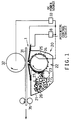
- the image recording apparatus includes a particle-flow modulating electrode member 1 (hereinafter referred to as “modulating electrode member”), and a back electrode in the form of a roll 32 (hereinafter referred to as “back electrode roll”) disposed right above the modulating electrode member 1.
- the back electrode roll 32 and the modulating electrode member 1 are spaced apart from each other by 1mm in the vertical direction, and cooperate to partially define a feed path of a recording medium 31 on which an image is formed by deposition of a toner as described below in detail.
- the back electrode roll 32 is supported rotatably about an axis perpendicular to the feed path of the recording medium 31, so that the medium 31 is fed along the feed path, by rotation of the back electrode roll 32.
- the feed path extends between a pair of rolls of an image fixing device 35 adapted to fix the toner deposited on the recording medium 31.
- the apparatus also includes a toner supply device 20 disposed generally below the modulating electrode member 1.
- the toner supply device 20 includes a toner casing 21, a toner carrier in the form of a roll 22 (hereinafter referred to as "toner carrier roll"), and a toner feed roll 23.
- the toner casing 21 is constructed to accommodate a mass of toner 26.
- the toner carrier roll 22 and the toner feed roll 23 are disposed in parallel with each other and the back electrode roll 32, so as to extend through the interior of the toner casing 21.
- These rolls 22 and 23 are supported rotatably in the same direction about respective parallel axes, in rolling contact with each other.
- the rotating directions of the rolls 22, 23 are indicated by arrow in Fig. 1.
- the toner carrier and feed rolls 22, 23 are positioned so that the contacting circumferential portions of the outer surfaces of these rolls 22, 23 are surrounded by or embedded in the mass of toner 26, and such that the point of rolling contact of the rolls 22, 23 is located a suitable distance above the bottom wall of the toner casing 21.
- the toner carrier roll 22 consists of a sponge core 24, and an outer metallic film in the form of a nickel film 25 which covers the circumferential surface of the sponge core 24.
- the nickel film 25 serves as a carrier electrode which cooperates with the modulating electrode member 1 to modulate flows of the toner particles 26 between the toner carrier 22 and the recording medium 31 through the modulating electrode member 1, as described below in detail.
- the nickel film 25 has a thickness of 20 ⁇ m.
- the toner carrier roll 22 is held in pressing contact at its nickel film 25 with the modulating electrode member 1 by the elasticity of the sponge core 24.
- the toner supply device 20 further has a restrictor blade 27 fixed to the toner casing 21, so that an operating portion of the blade 27 is disposed so as to contact a part of the outer circumference of the toner carrier roll 22, between two points at which the toner carrier roll 22 contacts the toner feed roll 23 and the modulating electrode member 1, respectively.
- the restrictor blade 27 acts to assure uniform condition of deposition of the toner particles 26 on the outer surface of the toner carrier roll 22, for example, uniform thickness and particle density of the toner layer 26.
- a layer of the toner particles 26 is transferred from the toner feed roll 23 to the toner carrier roll 22, such that the toner layer 26 is interposed between the rolls 22, 23.
- the toner layer 26 is moved with the rotating carrier roll 22 and is passed while being pressed by the restrictor blade 27 against the circumferential surface of the roll 22.
- the particle-flow modulating electrode member 1 consists of: a 30 ⁇ m-thick center substrate 2 made of an elastic, insulating material such as polyimide; a common shielding electrode in the form of a continuous layer 3 made of an electrically conductive material such formed on one of opposite surfaces of the center substrate 2; and a single array of control electrodes 4 which are spaced apart from each other in the direction parallel to the axis of the toner carrier roll 22.
- the control electrodes 4 are formed of a suitable electrically conductive material such as copper and have a 1 ⁇ m thickness.
- Each control electrode 4 has an annular portion and a straight elongate portion extending from the annular portion.
- the modulating electrode member 1 has a single row of apertures 6 each having a diameter of 120 ⁇ m.
- the apertures 6 are formed through the center substrate 2 and common shielding electrode 3 and through the annular portions of the respective control electrodes 4.
- the control electrodes 4 are formed such that the annular portion of each control electrode 4 surrounds the edge of the corresponding aperture 6.
- the number of the control electrodes 4 and apertures 6 is determined to be sufficient to cover a line of image dots to be formed on the recording medium 31, which line is perpendicular to the direction of feed of the medium 31.
- the modulating electrode member 1 is fixed to the toner casing 21 via fixed and movable ceramic bases 7a and 7b, such that the common shielding electrode 3 is located on the side of the recording medium 31 (that is, on the side of the back electrode roll 32), while the array of control electrodes 4 is located on the side of the toner carrier roll 22.
- the modulating electrode member 1 is positioned such that the row of aperture 6 is parallel to the axes of the toner carrier roll 22 and back electrode roll 32 and is aligned with a straight line connecting the axes of the rolls 22, 32.
- the apparatus incorporates a tensioning device as shown in Fig. 3.
- the tensioning device is associated with the ceramic bases 7a, 7b which are secured to the widthwise opposite ends of the modulating electrode member 1.
- the ceramic base 7a on one side of the electrode member 1 is fixed to the toner casing 21, while the movable ceramic base 7b on the other side of the electrode member 1 is slidable on the toner casing 21.
- On the fixed ceramic base 7a there is provided an integrated circuit 9 which is electrically connected to the control electrodes 4, for selectively applying imaging and non-imaging potentials between the control electrodes 4 and the carrier electrode 25.
- the movable ceramic base 7b is connected to a plurality of coil springs 10 which in turn are secured to the toner casing 21.
- a total biasing force of the coil springs 10 is applied as a tension to the modulating electrode member 1 in substantially the circumferential direction of the carrier roll 22, which is perpendicular to the axis of the toner carrier roll 22.
- the coil springs 10 may be replaced by other types of biasing means.
- the biasing force of the springs 10 may act on the electrode member 1 in either one of the clockwise and counterclockwise direction of the roll 22, as seen in Fig. 3.
- the electrode member 1 is preferably tensioned in the rotating direction of the roll 22.
- the tensioning device 7a, 7b, 10 indicated above cooperates with the sponge core 24 of the toner carrier roll 22 to provide tensioning means for applying a tension to the electrode member 1 so that the electrode member 1 including the elastic substrate 2 is held elastically curved along an upper part of the outer circumferential surface of the toner carrier roll 22 such that the electrode member 1 and the toner carrier are held in pressing contact with each other.
- This tensioning means therefore acts as biasing means for biasing the corresponding portions of the electrode member 1 and toner carrier roll 22 against each other for contact therebetween.
- the apparatus incorporates a control system operated according to image signals.
- the control system includes voltage applying means equipped with a potential control circuit 8.
- This potential control circuit 8 is electrically connected to the integrated circuit 9 and to the carrier electrode (nickel film) 25 of the toner carrier roll 22.
- the potential control circuit 8 is adapted to regulate, via the integrated circuit 9, an electric potential between each control electrode 4 and the carrier electrode 25, selectively to one of two different potential values, that is, imaging potential of 0V and non-imaging potential of -30V, according to the image signals corresponding to the individual control apertures 4.
- the control system also includes a DC power source or biasing circuit 33 connected between the back electrode roll 32 and the carrier electrode 24, for applying a biasing voltage between the back electrode roll 32 and the carrier electrode 24 such that the back electrode roll 32 has a positive potential of +2.2kV.
- the common shielding electrode 3 is connected to the DC biasing circuit 33.
- the toner carrier roll 22 and the toner feed roll 23 are rotated in rolling contact with each other in the same direction indicated by arrows in Fig. 1.
- a constant volume of the toner 26 is continuously transferred onto the outer circumferential surface of the roll 22, more precisely, onto the circumferential surface of the nickel film 25 that serves as the carrier electrode. Since the toner particles 26 are negatively electrostatically charged, the toner particles 26 are retained in the form of a layer on the nickel carrier electrode 25.
- the thickness of the toner layer 26 is reduced to a suitable value and made uniform by the restrictor blade 27, before each instantaneous portion of the toner layer 26 in the circumferential direction of the roll 22 reaches the point right below the row of apertures 6 of the modulating electrode member 1, by rotation of the toner carrier roll 22. It is noted that the toner layer 26 has a thickness value of 10 ⁇ m, at a portion thereof which passes through the nip between the toner carrier roll 22 and the row of control electrodes 4.
- the potential control circuit 8 applies the imaging potential of 0V between the control electrode 4 in question and the carrier electrode 24 of the toner carrier roll 22.
- the negatively charged toner particles 26 on a portion of the roll 22 adjacent to the aperture 4 in question are exposed to an electrostatic force acting in the direction toward the back electrode roll 32, in the presence of a potential difference between the back electrode roll 32 and the carrier electrode 25 on the roll 22, which difference produces a line of electric force in the direction from the back electrode roll 32 toward the carrier electrode 25.
- the potential control circuit 8 applies the non-imaging potential of -30V between the corresponding control electrode 4 and the carrier electrode 25. In this condition, a line of electric force is produced in the direction from the carrier electrode 25 toward the control electrode 4 in question, in the presence of a potential difference between the control electrode 4 and the carrier electrode 25. Since the potential of the control electrode 4 is smaller than that of the carrier electrode 25, the negatively charged toner particles 26 are retained on the carrier electrode 25 by an electrostatic force. Namely, the toner particles 26 adjacent to the control electrode 4 in question are not transferred to the recording medium 31 through the corresponding aperture 6, and the image signal does not cause an image dot to be formed on the medium 31.
- the potential is regulated in the manner as described above, by the potential control circuit 8 according to the respective image signals.
- a line of image dots parallel to the row of the apertures 4 is formed.
- the recording medium 31 is fed by rotation of the back electrode roll 32, along the feed path (perpendicular to the row of apertures 6), by a predetermined distance which corresponds to the line spacing or the size of each picture element.
- the formation of image dots and the feeding of the medium 31 are repeated to form successive lines of image dots.
- a predetermined number of these lines of image dots constitute a line of characters, for example, and successive lines of characters are recorded over a predetermined length of the medium 31 while the medium 31 is continuously fed.
- a crowd of the toner particles 26 is always present adjacent to each control electrode 4, or right below the lower open end of the corresponding aperture 6. Accordingly, the toner particles 26 can be transferred to the medium 31 with a sufficiently high response to a change in the potential between the control electrode 4 and the carrier electrode 25. Further, these control and carrier electrodes 4 and 25 are positioned very close to each other (with the thin layer of toner particles 26 interposed therebetween), the required magnitude of an electric field produced therebetween can be made relatively small. Thus, the present apparatus does not require expensive drive elements applying the imaging and non-imaging potentials between the control electrodes 4 and the toner carrier electrode 25.
- the layer of the negatively charged toner particles 26 is retained on the surface of the carrier electrode 25 and moved in sliding contact with the row of control electrodes 4, the toner particles 26 are unlikely to be deposited on the control electrodes 4 and therefore unlikely to plug the apertures 6.
- the present apparatus assures high quality of the image produced.
- the common shielding electrode 3 is provided on the modulating electrode member 1, for protecting the layer of the toner particles 26 except the portion right below the aperture row 6, against an influence of the electric field produced by the back electrode roll 32.
- the shielding electrode 3 is not essential according to the principle of the present invention.
- the short-circuiting between the control electrodes 4 and the carrier electrode 25 is prevented by the layer of the toner 26 which is interposed therebetween and which consists of an electrically insulating material.
- FIGs. 4 and 5 corresponding to Figs. 1 and 2 of the first embodiment, there will be described a second embodiment of this invention.
- Figs. 4 and 5 the same reference numerals as used in Figs. 1 and 2 are used to identify the same components.
- the present second embodiment of Figs. 4 and 5 uses a toner supply device 40 which is identical with the toner supply device 20 of the first embodiment, except for a toner carrier roll 42 which is entirely made of aluminum.
- a toner carrier roll 42 which is entirely made of aluminum.
- the entirety of the toner carrier roll 42 serves as a carrier electrode.
- the toner feed roll 23 and the restrictor blade 27 are disposed in close proximity to the carrier roll 42.
- the roll 23 and the blade 27 may be biased by suitable means such as springs against the carrier roll 42.
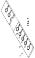
- the modulating electrode member 11 does not have a common shielding electrode. That is, the modulating electrode member 1 consists of a 25 ⁇ m thick polyimide substrate 12 and a single row of 1 ⁇ m-thick control electrodes 14 on one of opposite surfaces of the substrate 12, as shown in enlargement in Fig. 5.
- the electrode member 11 has apertures 16 formed through the substrate 12 and the annular portions of the respective control electrodes 14. Each aperture 16 has a diameter of 100 ⁇ m.
- the modulating electrode member 11 is secured to the toner casing 21 such that the row of control electrodes 14 is located on the side of the recording medium 31 or back electrode roll 32.
- a suitable tensioning means as illustrated in Fig. 3 is provided to apply a suitable tension to the modulating electrode member 11 so that a portion of the substrate 12 adjacent to the row of apertures 16 is held in contact with the toner carrier roll 42, with the toner layer 26 interposed therebetween.
- the potential control circuit 8 is adapted to selectively apply, via the integrated circuit 9 as shown in Fig. 3, different electric potentials, that is, non-imaging potential of 0V and imaging potential of +50V, between each control electrode 14 and the toner carrier roll 42 (carrier electrode), according to an image signal.
- the DC power source or biasing circuit 33 is adapted to apply a biasing voltage between the toner carrier roll 42 and the back electrode roll 32 (i.e., between the carrier electrode 42 and back electrode 32), such that the back electrode roll 32 has a positive potential of +1kV.
- an image dot is formed when the potential control circuit 8 applies the imaging potential of +50V between the control electrode 14 and the toner carrier roll 42.
- a potential difference between the control electrode 14 and the toner carrier roll 42 produces a line of electric force in the direction from the control electrode 14 toward the toner carrier roll 42, whereby the negatively electrostatically charged toner particles 26 are exposed to an electrostatic force, which causes the toner particles 26 to be transferred from the surface of the roll 42 toward the control electrode 14 while passing through the corresponding aperture 16.
- a stream of the toner particles 26 reaching the control electrode 14 is further transferred to the surface of the recording medium 31, in the presence of an electric field produced between the back electrode roll 32 and the control electrode 14.
- the toner particles 26 are deposited in an area of the medium 31 which is aligned with the aperture 16 in question, and an image dot is formed in that area, according to the image signal.
- the potential control circuit 8 applies 0V between the toner carrier roll 42 and the control electrode 14 in question. Since no electric field is produced between the toner carrier roll 42 and the control electrode 14, a portion of the toner particles 26 on the roll 42 which is adjacent to the control electrode 14 is not exposed to an electrostatic force sufficient to cause the toner particles 26 to be transferred toward the recording medium 31 through the aperture 16.
- the non-imaging potential of 0V is applied between the control electrode 14 and the toner carrier roll 42 when an image dot is not to be formed.
- a negative non-imaging potential may be applied. This negative potential will increase the force of retention of the toner particles 26 on the toner carrier roll 42, which is produced when the image signal does not require the formation of an image dot. Consequently, the corresponding local spot on the recording medium 31 is completely free from the toner particles 26, which might be otherwise more or less transferred from the toner carrier roll 42 even when the image signal inhibits the transfer through the aperture 16. Accordingly, the quality of the image produced is enhanced.
- the control electric field is produced between each control electrode 14 and the toner carrier roll 42 which are located on the opposite sides of the corresponding aperture 16.
- This arrangement assures easy and accurate control of a flow of the toner particles 26 through the aperture 16, and increased speed of movement of the toner particles from the toner carrier roll 42 to the recording medium 31.
- the electric field produced within each aperture 16 according to the image signal effectively prevents the passage of the toner particles 26 through the aperture 16, even if the toner particles 26 are more or less forced into the aperture 16 due to sliding contact of the toner layer 26 with the modulating electrode member 11 under some mechanical force.
- the distance between the modulating electrode member 1 and the toner carrier roll 42 is substantially zero, namely, the electrode member 1 and the roll 42 are spaced apart from each other by the very small thickness (about 10 ⁇ m) of the toner layer 16, the required magnitude of the electric field between the electrode member 11 and the roll 42 can be made relatively small, whereby the apparatus can use relatively inexpensive drive elements for the control electrodes 14.
- the row of control electrodes 14 and the toner carrier roll 42 are electrically insulated by the electrically insulating substrate 12 of the modulating electrode member 1.
- This arrangement is free from short-circuiting or direct electrical contact between the control electrodes 14 and the roll 42, which would take place in the event of discontinuity of the toner layer 16 or local exposure of the outer surface of the roll 42 due to some trouble with the toner supply device 40.
- the present apparatus assures high operating reliability and prolonged service life of the control electrodes 4.
- the toner layer contacts the electrically insulating substrate 12 of the electrode member 11, the toner particles 26 are unlikely to be deposited on the portion of the electrode member 11 around the apertures 16. Consequently, the apertures 16 are protected against plugging with the toner particles 26 deposited on the electrode member 11.
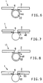
- FIGs. 6 through 9 there will be described third through sixth embodiments of the present invention, which are modified forms of the first embodiment in which the control electrodes 4 are disposed on the side of the toner carrier roll 22.
- the outer circumferential surface of the toner carrier roll 22 (more precisely, the carrier electrode 25 of the roll 22) is covered by an anti-shorting electrically insulating layer 44 which is made of an electrically insulating material such as polyimide and having a thickness of 10 ⁇ m.
- This anti-shorting layer 44 prevents short-circuiting between the toner carrier roll 22 and the control electrodes 4. Since the required thickness of the anti-shorting layer 44 is small, the provision of this layer 44 would not considerably increase the distance between the carrier electrode 25 and the control electrodes 4.
- the carrier roll 22 serves as a backing for the anti-shorting layer 44
- the thickness of the layer 44 can be made considerably smaller than that of the substrate 2, whereby the distance between the carrier roll 22 and the control electrodes 4 is shorter than the distance between the carrier roll 42 and the control electrodes 14 in the second embodiment of Figs. 4 and 5.
- the control electrodes 4 are covered by an anti-shorting electrically insulating layer 46 made of an electrically insulating material like the layer 44 of Fig. 6.
- This anti-shorting layer 46 prevents short-circuiting between the toner carrier roll 22 and the control electrodes 4. While only the control electrodes 4 may be covered by the anti-shorting layer 46, the entire lower surface of the substrate 2 of the electrode member 1 is preferably covered by the anti-shorting 46 as indicated in Fig. 7, so that the electrode member 1 has a flat or straight lower surface, without downward projection of the control electrodes 14. This arrangement is desirable for smooth movement of the toner particles in sliding or rolling contact with the portion of the lower surface of the electrode member 1 near the row of apertures 6.
- the toner carrier roll 22 is covered by an electrically resistive layer 48 made of a material which has a high electric resistivity value of between 1K ⁇ and 10T ⁇ .
- the electrically resistive layer 48 preferably has a thickness between 5-10 ⁇ m, and may be made of a mixture of polyimide and graphite.
- the layer 48 made of a mixture consisting of 30 parts by weight of SP1-200N as polyimide available from Shinnittetsu Kagaku (Japan) and 1 part by weight of Ketjen Black as graphite available from Lion Akzo (Japan) has surface electrical resistivity of 6.8G ⁇
- the layer 48 made of a mixture consisting of 10 parts by weight of SP1-200N identified above and 1 part by weight of HOP as graphite available from Nippon Kokuen (Japan) has surface electrical resistivity of 1.4T ⁇ .
- the electrically resistive layer 48 functions as an anti-shorting layer for preventing short-circuiting between the toner carrier roll 22 and the control electrodes 4.
- the layer 48 is effective to reduce the force by which the toner particles are retained on the carrier roll 22, and is therefore effective to reduce the required potential to transfer the toner particles from the carrier roll 22 toward the recording medium.
- This reduction of the toner retention force is supposed to be derived from an effect of the layer 48 of reducing the image force which acts on the toner particles, and appears to depend on the surface condition of the layer 48 which is different from that of the carrier roll 22.
- the control electrodes 4 and the lower surface of the substrate 2 of the modulating electrode member 1 are covered by an electrically resistive layer 50 made of a material similar to that of the layer 48 of Fig. 8.
- the layer 50 gives the electrode member 1 a constant thickness over the entire width and a straight lower surface, which assures smooth movement of the toner layer 26 toward the lower open end of the apertures 6.
- This electrically resistive layer 50 functions not only as an anti-shorting layer for preventing short-circuiting between the toner carrier roll 22 and the control electrodes 4, but also as an anti-static layer for preventing electrostatic charging of the insulating substrate 2 of the electrode member 1. Further, since the layer 50 is electrostatically equivalent to the electrodes 4, the layer 50 does not increase the distance between the carrier roll 22 and the electrodes 22.
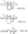
- Figs. 10 and 11 there will be described seventh and eighth embodiments of this invention, which are modified forms of the second embodiment of Figs. 4 and 5 in which the control electrodes 14 are formed on the side of the recording medium 31, or on the side remote from the toner carrier roll 42.
- the outer circumferential surface of the toner carrier roll 42 is covered by an electrically resistive layer 52 similar to the layer 48 of Fig. 8.
- This layer 52 serves as an anti-shorting layer for preventing short-circuiting between the toner carrier roll 42 and the control electrodes 14, which may occur due to penetration of the material of the electrodes 14 through the apertures 16 when the apertures 16 are formed.
- the apertures 16 are formed by application of a laser beam through the annular portions of the control electrodes 14 and the insulating substrate 12. At this time, the material such as copper of the electrodes 14 may partially flow into the formed apertures 16 and remain on the inner surfaces of the apertures 16 and around the lower edge of the apertures 16. This may cause short-circuiting between the toner carrier roll 42 and the control electrodes 14.
- the layer 52 may be relaced by an electrically insulating layer similar to the layer 44 of Fig. 6.
- the entire lower surface of the substrate 12 of the modulating electrode member 11 is covered by an electrically resistive layer 54 similar to the layer 50 of Fig. 9.
- This layer 54 serves as an anti-static layer for preventing electrostatic charging of the insulating substrate 12 of the electrode member 11.
- the electrically resistive layer 54 may be replaced by an electrically conductive layer to prevent the electrostatic charging of the substrate 12, the electrically resistive anti-static layer is preferred since the electrically conductive anti-static layer undesirably has an effect of shielding an electric field produced to transfer the toner particles toward the recording medium.
- an electrically resistive layer 56 covers only the exposed portion of the lower surface of the insulating substrate 2 of the electrode member 1. Namely, the control electrodes 4 provided on the lower surface of the substrate 2 of the electrode member 1 are not covered by the electrically resistive layer 56.
- the thickness of the layer 56 is selected to be equal to that of the control electrodes 4 so that the electrode member 1 has a constant thickness and a straight lower surface over the entire width.
- the layer 56 serves only as an anti-static layer for preventing electrostatic charging of the substrate 2.
Landscapes
- Physics & Mathematics (AREA)
- General Physics & Mathematics (AREA)
- Printers Or Recording Devices Using Electromagnetic And Radiation Means (AREA)
- Electrophotography Using Other Than Carlson'S Method (AREA)
Claims (27)
- Appareil d'enregistrement d'image pour former une image sur un support d'enregistrement (31) par dépôt d'encre en poudre (26), ledit appareil comprenant :(a) un élément formant électrode de modulation de flot de particules (1, 11) ayant une pluralité d'ouvertures (6, 16) formées à travers ce dernier et une pluralité d'électrodes de commande (4) correspondant auxdites ouvertures ;(b) un dispositif d'alimentation en encre en poudre (20, 40) comprenant un support d'encre en poudre (22, 42) qui est disposé sur un des côtés opposés dudit élément formant électrode et qui porte une couche de ladite encre en poudre sur une surface extérieure de ce dernier ;(c) des moyens d'application de tension (8) pour appliquer une tension commandée à chaque électrode de ladite pluralité d'électrodes de commande, selon des informations d'image représentatives de ladite image, et pour moduler, de ce fait, des flots de particules de ladite encre en poudre à travers ladite pluralité d'ouvertures vers ledit support d'enregistrement situé de l'autre côté dudit élément formant électrode ; et(d) des moyens de poussée (7a, 7b, 10, 24) pour pousser des parties correspondantes dudit support d'encre en poudre (22, 42) et dudit élément formant électrode de modulation de flot de particules (1, 11) les unes contre les autres pour établir un contact entre elles, lesdites parties correspondantes étant adjacentes à ladite pluralité d'ouvertures (6, 16) ; dans lequelledit élément formant électrode de modulation de flot de particules (1, 11) est constitué par un substrat (2, 12) ayant une certaine élasticité ; etlesdits moyens de poussée comprennent des moyens tendeurs (7a, 7b, 10, 24) pour appliquer un effort de tension audit élément formant électrode, les moyens tendeurs comprenant un dispositif tendeur (10) relié entre un côté particulier de l'élément formant électrode (1, 11) et un élément formant boítier de sorte que l'effort de tension est appliqué sensiblement dans la direction circonférentielle du support d'encre en poudre (22, 42) et de sorte que ledit élément formant électrode est maintenu incurvé, de façon élastique, le long d'une partie de ladite surface extérieure dudit support d'encre en poudre (22, 42) de sorte que ledit élément formant électrode est en contact de pression avec ledit support d'encre en poudre.
- Appareil d'enregistrement d'image selon la revendication 1, dans lequel une des extrémités opposées dudit élément formant électrode (1, 11) est mobile dans le sens d'amenée dudit support d'enregistrement (31) et dans lequel ledit dispositif tendeur comprend des moyens (7a, 7b, 10) pour appliquer un effort de tension audit élément formant électrode (1, 11) dans le sens d'amenée dudit support d'enregistrement (31).
- Appareil d'enregistrement d'image selon la revendication 1 ou 2, dans lequel ledit support d'encre en poudre (22) comprend un noyau (24) fabriqué à partir d'une matière élastique et un film métallique (25) formant une électrode de support qui recouvre une surface dudit noyau, ledit support d'encre en poudre étant positionné par rapport audit élément formant électrode (1) de sorte que ledit noyau (24) presse ledit film métallique sur ledit élément formant électrode.
- Appareil d'enregistrement d'image selon la revendication 3, dans lequel lesdits moyens d'application de tension (8) comprennent un circuit de commande de potentiel pour réguler un potentiel électrique entre ladite électrode de support et chacune des électrodes de commande (4, 14), de manière sélective pour un premier potentiel qui est suffisant pour provoquer le passage d'un jet de particules de ladite encre en poudre (26) à travers l'ouverture (6, 16) correspondant à chaque dite électrode de commande, et pour un second potentiel qui n'est pas suffisant pour provoquer le passage dudit jet de particules à travers l'ouverture correspondante.
- Appareil d'enregistrement d'image selon la revendication 4, dans lequel ledit élément formant électrode de modulation de flot de particules (1) comprend un substrat (2) fabriqué à partir d'une matière électriquement isolante, et ladite pluralité d'électrodes de commande (4) est formée sur une des surfaces opposées dudit substrat du côté dudit support d'encre en poudre (22), de sorte que chaque dite électrode de commande entoure un bord de ladite ouverture correspondante (6).
- Appareil d'enregistrement d'image selon la revendication 5, dans lequel au moins un parmi un groupement desdites électrodes de commande (4) et ledit support d'encre en poudre (22, 42) est recouvert par une couche anti-court-circuit (44, 46, 48, 50) pour empêcher des courts-circuits entre lesdites électrodes de commande et ledit support d'encre en poudre.
- Appareil d'enregistrement d'image selon la revendication 6, dans lequel ladite couche anti-court-circuit est constituée par une couche électriquement isolante (44, 46).
- Appareil d'enregistrement d'image selon la revendication 6, dans lequel ladite couche anti-court-circuit est constituée par une couche électriquement résistive (48, 50) ayant une valeur de résistance électrique comprise entre 1 kΩ et 1 TΩ.
- Appareil d'enregistrement d'image selon l'une quelconque des revendications 4 à 8, comprenant, de plus, une électrode arrière (32) disposée de façon à supporter ledit support d'enregistrement (31) au niveau d'un des côtés opposés dudit support d'enregistrement distant dudit élément formant électrode de modulation de flot de particules (1, 11) et un circuit de polarisation (33) pour appliquer une tension de polarisation entre ladite électrode de support et ladite électrode arrière de sorte que ladite électrode arrière a un potentiel positif.
- Appareil d'enregistrement d'image selon la revendication 9, dans lequel ledit élément formant électrode de modulation de flot de particules (1) comprend, de plus, une électrode de blindage (3) formée sur une des surfaces opposées dudit substrat (2) distant de ladite pluralité d'électrodes de commande (4), ledit appareil comprenant, de plus, un circuit de connexion pour relier ladite électrode de support (25) et ladite électrode de blindage (3).
- Appareil d'enregistrement d'image selon la revendication 10, dans lequel ledit circuit de commande de potentiel (8, 9) régule ledit potentiel électrique entre ladite électrode de support (25) et chaque dite électrode de commande (4), de sorte qu'un potentiel de chaque dite électrode de commande peut changer entre une valeur égale à celle de ladite électrode de support et une valeur inférieure à celle de ladite électrode de support.
- Appareil d'enregistrement d'image selon la revendication 4, dans lequel ledit élément formant électrode de modulation de flot de particules (11) comprend un substrat (12) fabriqué à partir d'une matière électriquement isolante, et ladite pluralité d'électrodes de commande (14) est formée sur une des surfaces opposées dudit substrat du côté dudit support d'enregistrement (31), de sorte que chaque dite électrode de commande entoure un bord de ladite ouverture correspondante (16).
- Appareil d'enregistrement d'image selon la revendication 12, dans lequel au moins un parmi ledit support d'encre en poudre (42) et ledit substrat (12) est recouvert par une couche électriquement résistive (52, 54).
- Appareil d'enregistrement d'image selon la revendication 13, dans lequel ladite couche électriquement résistive a une valeur de résistance électrique comprise entre 1 kΩ et 1 TΩ.
- Appareil d'enregistrement d'image selon la revendication 12, comprenant, de plus, une électrode arrière (32) disposée de façon à supporter ledit support d'enregistrement (31) au niveau d'un des côtés opposés dudit support d'enregistrement distant dudit élément formant électrode de modulation de flot de particules (11), et un circuit de polarisation (33) pour appliquer une tension de polarisation entre ladite électrode de support et ladite électrode arrière de sorte que ladite électrode arrière a un potentiel positif.
- Appareil d'enregistrement d'image selon la revendication 15, dans lequel ledit circuit de commande de potentiel (8, 9) régule ledit potentiel électrique entre ladite électrode de support (42) et chaque dite électrode de commande (14), de sorte qu'un potentiel de chaque dite électrode de commande peut changer entre une valeur non supérieure à celle de ladite électrode de support et une valeur supérieure à celle de ladite électrode de support.
- Appareil d'enregistrement d'image selon la revendication 1, 2 ou 3, dans lequel ledit élément formant électrode de modulation de flot de particules (1) comprend un substrat (2) fabriqué à partir d'une matière électriquement isolante et ayant ladite pluralité d'ouvertures (6), une électrode commune (3) disposée sur une des surfaces opposées dudit substrat et sous la forme d'une couche continue commune à la totalité de ladite pluralité d'ouvertures, et ladite pluralité d'électrodes de commande (4) qui correspond respectivement auxdites ouvertures, et dans lequel lesdits moyens d'application de tension (8) régulent un potentiel électrique entre ladite électrode commune (3) et chacune desdites électrodes de commande (4), de manière sélective pour un premier potentiel qui est suffisant pour provoquer le passage d'un jet de particules de ladite encre en poudre (26) à travers l'ouverture (6) correspondant à chaque dite électrode de commande, et pour un second potentiel qui n'est pas suffisant pour provoquer le passage dudit jet de particules à travers l'ouverture correspondante.
- Appareil d'enregistrement d'image selon l'une quelconque des revendications 1 à 17, dans lequel ledit support d'encre en poudre est constitué par un rouleau de support d'encre en poudre (22, 42) qui est supporté, de façon rotative, autour d'un axe de ce dernier, au moins une partie extérieure dudit rouleau, qui réalise une surface extérieure dudit rouleau, étant formée d'une matière électriquement conductrice et servant d'électrode de support.
- Appareil d'enregistrement d'image selon la revendication 18, dans lequel ledit dispositif d'alimentation en encre en poudre (20, 40), et un rouleau d'amenée d'encre en poudre (23) supporté, de façon rotative, autour d'un axe parallèle audit axe dudit rouleau de support d'encre en poudre, dans le même sens que ledit rouleau de support d'encre en poudre, en étroite proximité ou en contact avec ledit rouleau de support d'encre en poudre, ledit dispositif d'alimentation en encre en poudre comprenant, de plus, un boítier d'encre en poudre (21) qui loge une masse de ladite encre en poudre (26) de sorte que ladite masse d'encre en poudre logée dans ledit boítier d'encre en poudre entoure au moins des parties circonférentielles s'accouplant desdites surfaces extérieures desdits rouleaux de support et d'amenée d'encre en poudre, ledit boítier d'encre en poudre ayant un fond inférieur auxdites parties s'accouplant desdits rouleaux de support et d'amenée d'encre en poudre.
- Appareil d'enregistrement d'image selon la revendication 19, dans lequel ledit dispositif d'alimentation en encre en poudre comprend, de plus, une lame de limitation (27) disposée le long et à côté d'une partie d'une circonférence extérieure dudit rouleau de support d'encre en poudre (22, 42), entre deux points au niveau desquels ledit rouleau de support d'encre en poudre est le plus proche dudit rouleau de support d'encre en poudre et dudit élément formant électrode de modulation de flot de particules (1, 11), de sorte que ladite lame de limitation vient en contact avec une couche de particules de ladite encre en poudre transférées depuis ledit rouleau d'amenée d'encre en poudre vers ledit rouleau de support d'encre en poudre, et assure, de ce fait, un état uniforme de dépôt des particules de ladite encre en poudre sur ladite surface extérieure dudit rouleau de support d'encre en poudre.
- Appareil d'enregistrement d'image selon la revendication 20, comprenant, de plus, des seconds moyens de poussée, pour pousser ladite lame de limitation (27) et ladite surface extérieure dudit rouleau de support d'encre en poudre (22, 42) l'une vers l'autre.
- Appareil d'enregistrement d'image selon l'une quelconque des revendications 1 à 21, comprenant, de plus, un rouleau formant électrode arrière (32) disposé pour un contact roulant avec l'une des surfaces opposées dudit support d'enregistrement (31) distant dudit élément formant électrode de modulation de flot de particules (1, 11), ledit rouleau formant électrode arrière servant d'électrode au moins au niveau d'une partie extérieure de ce dernier qui possède une surface extérieure pour un contact de roulement avec ladite surface particulière dudit support d'enregistrement.
- Appareil d'enregistrement d'image selon la revendication 1, dans lequel ledit élément formant électrode de modulation de flot de particules (1, 11) comprend un substrat (2, 12) fabriqué à partir d'une matière électriquement isolante, et dans lequel au moins une des surfaces opposées dudit substrat est recouverte par une couche antistatique (3, 50, 54, 56) pour empêcher le chargement électrostatique dudit substrat.
- Appareil d'enregistrement d'image selon la revendication 23, dans lequel ladite couche antistatique est constituée par une couche électriquement résistive (50, 54, 56) qui a une résistance électrique comprise entre 1 kΩ et 1 TΩ.
- Appareil d'enregistrement d'image selon la revendication 24, dans lequel lesdites électrodes de commande (14) sont disposées sur une desdites surfaces opposées dudit substrat (2) dudit élément formant électrode (1) du côté dudit support d'encre en poudre (22), et dans lequel ladite couche électriquement résistive (50, 56) recouvre ladite surface particulière desdites surfaces opposées dudit substrat.
- Appareil d'enregistrement d'image selon la revendication 24, dans lequel lesdites électrodes de commande (14) sont disposées sur une desdites surfaces opposées dudit substrat (12) dudit élément formant électrode (11) du côté dudit support d'enregistrement (31), et dans lequel ladite couche électriquement résistive (54) recouvre l'autre surface desdites surfaces opposées dudit substrat qui est du côté dudit support d'encre en poudre.
- Appareil d'enregistrement d'image selon la revendication 23, dans lequel ladite couche antistatique est constituée par une couche électriquement conductrice (3) qui recouvre une desdites surfaces opposées dudit substrat (2) .
Applications Claiming Priority (4)
| Application Number | Priority Date | Filing Date | Title |
|---|---|---|---|
| JP23352292A JP3203793B2 (ja) | 1992-09-01 | 1992-09-01 | 画像形成装置 |
| JP233522/92 | 1992-09-01 | ||
| JP25449492 | 1992-09-24 | ||
| JP254494/92 | 1992-09-24 |
Publications (2)
| Publication Number | Publication Date |
|---|---|
| EP0587366A1 EP0587366A1 (fr) | 1994-03-16 |
| EP0587366B1 true EP0587366B1 (fr) | 1998-06-03 |
Family
ID=26531073
Family Applications (1)
| Application Number | Title | Priority Date | Filing Date |
|---|---|---|---|
| EP93306897A Expired - Lifetime EP0587366B1 (fr) | 1992-09-01 | 1993-09-01 | Dispositif d'enregistrement d'images avec élément porteur de toner et électrode pour la modulation d'un flux de particules |
Country Status (3)
| Country | Link |
|---|---|
| US (1) | US5552814A (fr) |
| EP (1) | EP0587366B1 (fr) |
| DE (1) | DE69318908T2 (fr) |
Families Citing this family (40)
| Publication number | Priority date | Publication date | Assignee | Title |
|---|---|---|---|---|
| US5508723A (en) * | 1992-09-01 | 1996-04-16 | Brother Kogyo Kabushiki Kaisha | Electric field potential control device for an image forming apparatus |
| JPH0752443A (ja) * | 1993-08-19 | 1995-02-28 | Brother Ind Ltd | 画像形成装置 |
| JPH07178954A (ja) * | 1993-12-24 | 1995-07-18 | Brother Ind Ltd | 画像形成装置 |
| JP3274761B2 (ja) * | 1994-03-02 | 2002-04-15 | ブラザー工業株式会社 | 画像形成装置 |
| JPH07256918A (ja) * | 1994-03-28 | 1995-10-09 | Brother Ind Ltd | 記録装置 |
| JPH07309028A (ja) * | 1994-05-17 | 1995-11-28 | Brother Ind Ltd | 画像形成装置 |
| JP3313883B2 (ja) * | 1994-05-26 | 2002-08-12 | ブラザー工業株式会社 | 画像形成装置 |
| JPH07329344A (ja) * | 1994-06-09 | 1995-12-19 | Brother Ind Ltd | 圧電体及び画像形成装置 |
| JP3255332B2 (ja) * | 1994-07-12 | 2002-02-12 | ブラザー工業株式会社 | 画像形成装置 |
| JPH0834136A (ja) * | 1994-07-22 | 1996-02-06 | Brother Ind Ltd | 画像形成装置 |
| JPH0858140A (ja) * | 1994-08-19 | 1996-03-05 | Brother Ind Ltd | 画像形成装置 |
| JP3258501B2 (ja) * | 1994-09-29 | 2002-02-18 | ブラザー工業株式会社 | 画像形成装置 |
| JP3197438B2 (ja) * | 1994-11-04 | 2001-08-13 | シャープ株式会社 | カラー画像形成装置 |
| EP0712056B1 (fr) * | 1994-11-08 | 1999-08-04 | Agfa-Gevaert N.V. | Dispositif d'impression électrostatique direct avec tête d'impression spéciale |
| DE69511213T2 (de) * | 1994-11-08 | 2000-04-13 | Agfa-Gevaert N.V., Mortsel | Vorrichtung zum direkten elektrostatischen Drucken mit speziellem Druckkopf |
| JP3290830B2 (ja) * | 1994-11-09 | 2002-06-10 | シャープ株式会社 | 画像形成装置 |
| JP3411434B2 (ja) * | 1994-12-27 | 2003-06-03 | シャープ株式会社 | 画像形成装置 |
| US5905516A (en) * | 1995-04-25 | 1999-05-18 | Brother Kogyo Kabushiki Kaisha | Image forming apparatus having at least one reinforcing member |
| JPH08310035A (ja) * | 1995-05-16 | 1996-11-26 | Brother Ind Ltd | 画像形成装置 |
| US5988794A (en) * | 1995-06-09 | 1999-11-23 | Brother Kogyo Kabushiki Kaisha | Aperture electrode assembly for an image forming device |
| EP0753413B1 (fr) | 1995-07-14 | 1999-12-01 | Agfa-Gevaert N.V. | Structure de tête d'impression pour l'utilisation dans un dispositif DEP |
| EP0754557B1 (fr) * | 1995-07-18 | 1998-10-14 | Agfa-Gevaert N.V. | Structure de tête d'impression pour son utilisation dans une imprimante électrostatique direct (DEP) |
| JPH0971000A (ja) * | 1995-09-06 | 1997-03-18 | Brother Ind Ltd | 記録用電極 |
| JPH09141920A (ja) * | 1995-11-17 | 1997-06-03 | Brother Ind Ltd | 画像形成装置用電極体 |
| DE69706723T2 (de) * | 1996-01-19 | 2002-07-11 | Sharp K.K., Osaka | Bilderzeugungsgerät |
| US5955228A (en) * | 1996-03-14 | 1999-09-21 | Ricoh Company, Ltd | Method and apparatus for forming a powder image |
| JPH09314887A (ja) * | 1996-05-27 | 1997-12-09 | Brother Ind Ltd | 画像形成装置 |
| JPH1010784A (ja) * | 1996-06-27 | 1998-01-16 | Brother Ind Ltd | 正帯電性一成分現像剤並びにその現像剤を用いた画像形成装置 |
| US5895702A (en) * | 1996-07-16 | 1999-04-20 | Ngk Insulators, Ltd. | Ceramic member |
| JPH1097093A (ja) * | 1996-09-24 | 1998-04-14 | Brother Ind Ltd | トナー及び画像形成装置 |
| JPH10200667A (ja) * | 1997-01-08 | 1998-07-31 | Brother Ind Ltd | 画像形成装置 |
| US6227655B1 (en) * | 1997-04-09 | 2001-05-08 | Agfa-Gevaert | DEP (direct electrostatic printing) device maintaining a constant distance between printhead structure and toner delivery means |
| DE69700075T2 (de) * | 1997-04-29 | 1999-07-15 | Agfa-Gevaert N.V., Mortsel | Vorrichtung zum direkten elektrostatischen Drucken (DEP) mit konstantem Abstand zwischen der Druckkopfstruktur und den Tonerzufuhrmitteln |
| JPH10329352A (ja) | 1997-06-04 | 1998-12-15 | Brother Ind Ltd | 記録用電極体 |
| JP3462718B2 (ja) * | 1997-06-27 | 2003-11-05 | シャープ株式会社 | 画像形成装置 |
| JPH1178104A (ja) * | 1997-09-12 | 1999-03-23 | Brother Ind Ltd | 記録ヘッド並びに画像形成装置 |
| JPH11105331A (ja) | 1997-10-03 | 1999-04-20 | Brother Ind Ltd | 電極体及び電極体の製造方法 |
| US6286936B1 (en) | 1998-03-24 | 2001-09-11 | Array Aktiebolag | Image forming apparatus and image forming method |
| JP3280308B2 (ja) | 1998-04-23 | 2002-05-13 | ブラザー工業株式会社 | 記録ヘッドおよびその製造方法 |
| WO2002051642A1 (fr) * | 2000-12-27 | 2002-07-04 | Array Ab | Appareil et procede d'impression directe |
Citations (1)
| Publication number | Priority date | Publication date | Assignee | Title |
|---|---|---|---|---|
| EP0488652A2 (fr) * | 1990-11-26 | 1992-06-03 | Mita Industrial Co., Ltd. | Appareil de formation d'images |
Family Cites Families (11)
| Publication number | Priority date | Publication date | Assignee | Title |
|---|---|---|---|---|
| US3689935A (en) * | 1969-10-06 | 1972-09-05 | Electroprint Inc | Electrostatic line printer |
| US4282303A (en) * | 1980-05-05 | 1981-08-04 | Xerox Corporation | Development method and apparatus |
| US4568955A (en) * | 1983-03-31 | 1986-02-04 | Tokyo Shibaura Denki Kabushiki Kaisha | Recording apparatus using a toner-fog generated by electric fields applied to electrodes on the surface of the developer carrier |
| US4573061A (en) * | 1983-05-18 | 1986-02-25 | Canon Kabushiki Kaisha | Image recording apparatus |
| US4855757A (en) * | 1987-06-17 | 1989-08-08 | Intermec Corporation | Thermal printhead with static electricity discharge capability |
| US4912489A (en) * | 1988-12-27 | 1990-03-27 | Xerox Corporation | Direct electrostatic printing apparatus with toner supply-side control electrodes |
| US5153611A (en) * | 1989-07-25 | 1992-10-06 | Mita Industrial Co., Ltd. | Image forming apparatus |
| US5010355A (en) * | 1989-12-26 | 1991-04-23 | Xerox Corporation | Ink jet printhead having ionic passivation of electrical circuitry |
| JP2520500B2 (ja) * | 1990-05-30 | 1996-07-31 | 三田工業株式会社 | 画像形成装置 |
| US5229794A (en) * | 1990-10-04 | 1993-07-20 | Brother Kogyo Kabushiki Kaisha | Control electrode for passing toner to obtain improved contrast in an image recording apparatus |
| US5453768A (en) * | 1993-11-01 | 1995-09-26 | Schmidlin; Fred W. | Printing apparatus with toner projection means |
-
1993
- 1993-08-27 US US08/112,471 patent/US5552814A/en not_active Expired - Lifetime
- 1993-09-01 EP EP93306897A patent/EP0587366B1/fr not_active Expired - Lifetime
- 1993-09-01 DE DE69318908T patent/DE69318908T2/de not_active Expired - Lifetime
Patent Citations (1)
| Publication number | Priority date | Publication date | Assignee | Title |
|---|---|---|---|---|
| EP0488652A2 (fr) * | 1990-11-26 | 1992-06-03 | Mita Industrial Co., Ltd. | Appareil de formation d'images |
Also Published As
| Publication number | Publication date |
|---|---|
| US5552814A (en) | 1996-09-03 |
| EP0587366A1 (fr) | 1994-03-16 |
| DE69318908D1 (de) | 1998-07-09 |
| DE69318908T2 (de) | 1998-10-22 |
Similar Documents
| Publication | Publication Date | Title |
|---|---|---|
| EP0587366B1 (fr) | Dispositif d'enregistrement d'images avec élément porteur de toner et électrode pour la modulation d'un flux de particules | |
| US5640185A (en) | Image recording apparatus having aperture electrode with tension application means and tension increasing means and opposing electrode for applying toner image onto image receiving sheet | |
| US5038159A (en) | Apertured printhead for direct electrostatic printing | |
| US5666147A (en) | Method for dynamically positioning a control electrode array in a direct electrostatic printing device | |
| US5414500A (en) | Image recording apparatus | |
| US4831394A (en) | Electrode assembly and image recording apparatus using same | |
| US5966151A (en) | Image forming apparatus | |
| US4233611A (en) | Recording head for electrostatic printing apparatus | |
| US5495273A (en) | Image recording apparatus having spacer between aperture electrode and opposing electrode | |
| US4314257A (en) | Thermomagnetic recording apparatus | |
| US5233395A (en) | Image forming apparatus having a transfer brush of electroconductive fibers | |
| US5504509A (en) | Image forming apparatus with specific aperture electrode unit | |
| US5523777A (en) | Aperture electrode with overlying charge member | |
| EP1040010A2 (fr) | Procede de positionnement d'un groupe d'electrodes de commande dans un dispositif d'impression electrostatique directe | |
| US5666148A (en) | Image forming apparatus with an electrode unit having plural electrodes | |
| US5867190A (en) | Image forming unit with control electrodes arranged to be electrically insulated from each other | |
| US6039435A (en) | Image forming apparatus with restructured image data | |
| US6336712B1 (en) | Image formation apparatus having a toner flow control member with a protection layer | |
| US5883649A (en) | Image forming apparatus using an aperture electrode with improved toner passage by controlling toner flow to and from the apertures | |
| US5305025A (en) | Elastica counter electrode for an electrostatic recorder | |
| JP3203793B2 (ja) | 画像形成装置 | |
| KR200180194Y1 (ko) | 레이저프린터의감광벨트접지장치 | |
| JPH0920029A (ja) | 画像形成装置 | |
| JP3127516B2 (ja) | 画像記録装置 | |
| JPH0732642A (ja) | 画像形成装置 |
Legal Events
| Date | Code | Title | Description |
|---|---|---|---|
| PUAI | Public reference made under article 153(3) epc to a published international application that has entered the european phase |
Free format text: ORIGINAL CODE: 0009012 |
|
| AK | Designated contracting states |
Kind code of ref document: A1 Designated state(s): DE FR GB |
|
| 17P | Request for examination filed |
Effective date: 19940825 |
|
| 17Q | First examination report despatched |
Effective date: 19960129 |
|
| GRAG | Despatch of communication of intention to grant |
Free format text: ORIGINAL CODE: EPIDOS AGRA |
|
| GRAG | Despatch of communication of intention to grant |
Free format text: ORIGINAL CODE: EPIDOS AGRA |
|
| GRAH | Despatch of communication of intention to grant a patent |
Free format text: ORIGINAL CODE: EPIDOS IGRA |
|
| GRAH | Despatch of communication of intention to grant a patent |
Free format text: ORIGINAL CODE: EPIDOS IGRA |
|
| GRAA | (expected) grant |
Free format text: ORIGINAL CODE: 0009210 |
|
| AK | Designated contracting states |
Kind code of ref document: B1 Designated state(s): DE FR GB |
|
| REF | Corresponds to: |
Ref document number: 69318908 Country of ref document: DE Date of ref document: 19980709 |
|
| ET | Fr: translation filed | ||
| PLBE | No opposition filed within time limit |
Free format text: ORIGINAL CODE: 0009261 |
|
| STAA | Information on the status of an ep patent application or granted ep patent |
Free format text: STATUS: NO OPPOSITION FILED WITHIN TIME LIMIT |
|
| 26N | No opposition filed | ||
| REG | Reference to a national code |
Ref country code: GB Ref legal event code: IF02 |
|
| PGFP | Annual fee paid to national office [announced via postgrant information from national office to epo] |
Ref country code: GB Payment date: 20120829 Year of fee payment: 20 |
|
| PGFP | Annual fee paid to national office [announced via postgrant information from national office to epo] |
Ref country code: FR Payment date: 20120910 Year of fee payment: 20 |
|
| PGFP | Annual fee paid to national office [announced via postgrant information from national office to epo] |
Ref country code: DE Payment date: 20120928 Year of fee payment: 20 |
|
| REG | Reference to a national code |
Ref country code: DE Ref legal event code: R071 Ref document number: 69318908 Country of ref document: DE |
|
| REG | Reference to a national code |
Ref country code: GB Ref legal event code: PE20 Expiry date: 20130831 |
|
| PG25 | Lapsed in a contracting state [announced via postgrant information from national office to epo] |
Ref country code: DE Free format text: LAPSE BECAUSE OF EXPIRATION OF PROTECTION Effective date: 20130903 |
|
| PG25 | Lapsed in a contracting state [announced via postgrant information from national office to epo] |
Ref country code: GB Free format text: LAPSE BECAUSE OF EXPIRATION OF PROTECTION Effective date: 20130831 |