EP0587379A2 - Connecteur bipolaire coaxial pour dispositif médical implantable - Google Patents
Connecteur bipolaire coaxial pour dispositif médical implantable Download PDFInfo
- Publication number
- EP0587379A2 EP0587379A2 EP93306968A EP93306968A EP0587379A2 EP 0587379 A2 EP0587379 A2 EP 0587379A2 EP 93306968 A EP93306968 A EP 93306968A EP 93306968 A EP93306968 A EP 93306968A EP 0587379 A2 EP0587379 A2 EP 0587379A2
- Authority
- EP
- European Patent Office
- Prior art keywords
- lead
- receptacle
- medical device
- implantable medical
- terminal
- Prior art date
- Legal status (The legal status is an assumption and is not a legal conclusion. Google has not performed a legal analysis and makes no representation as to the accuracy of the status listed.)
- Withdrawn
Links
- 239000004020 conductor Substances 0.000 claims abstract description 34
- 210000001519 tissue Anatomy 0.000 description 9
- 230000000747 cardiac effect Effects 0.000 description 7
- 238000007789 sealing Methods 0.000 description 5
- 239000000463 material Substances 0.000 description 4
- 239000012212 insulator Substances 0.000 description 3
- 230000013011 mating Effects 0.000 description 3
- 239000004593 Epoxy Substances 0.000 description 2
- 210000001124 body fluid Anatomy 0.000 description 2
- 239000010839 body fluid Substances 0.000 description 2
- 239000000919 ceramic Substances 0.000 description 2
- 230000008878 coupling Effects 0.000 description 2
- 238000010168 coupling process Methods 0.000 description 2
- 238000005859 coupling reaction Methods 0.000 description 2
- 239000011521 glass Substances 0.000 description 2
- 229910001220 stainless steel Inorganic materials 0.000 description 2
- 239000010935 stainless steel Substances 0.000 description 2
- 230000002747 voluntary effect Effects 0.000 description 2
- 210000001015 abdomen Anatomy 0.000 description 1
- 210000000577 adipose tissue Anatomy 0.000 description 1
- 210000000481 breast Anatomy 0.000 description 1
- 229910010293 ceramic material Inorganic materials 0.000 description 1
- 239000012530 fluid Substances 0.000 description 1
- 238000002513 implantation Methods 0.000 description 1
- 230000007257 malfunction Effects 0.000 description 1
- 238000000034 method Methods 0.000 description 1
- 239000012811 non-conductive material Substances 0.000 description 1
- 230000000149 penetrating effect Effects 0.000 description 1
- 239000004033 plastic Substances 0.000 description 1
- 229920003023 plastic Polymers 0.000 description 1
- 229920000642 polymer Polymers 0.000 description 1
- 229920001296 polysiloxane Polymers 0.000 description 1
- 230000000717 retained effect Effects 0.000 description 1
- 230000000638 stimulation Effects 0.000 description 1
- 239000000126 substance Substances 0.000 description 1
- 210000003462 vein Anatomy 0.000 description 1
- 210000002620 vena cava superior Anatomy 0.000 description 1
Images

Classifications
-
- A—HUMAN NECESSITIES
- A61—MEDICAL OR VETERINARY SCIENCE; HYGIENE
- A61N—ELECTROTHERAPY; MAGNETOTHERAPY; RADIATION THERAPY; ULTRASOUND THERAPY
- A61N1/00—Electrotherapy; Circuits therefor
- A61N1/18—Applying electric currents by contact electrodes
- A61N1/32—Applying electric currents by contact electrodes alternating or intermittent currents
- A61N1/36—Applying electric currents by contact electrodes alternating or intermittent currents for stimulation
- A61N1/372—Arrangements in connection with the implantation of stimulators
- A61N1/375—Constructional arrangements, e.g. casings
- A61N1/3752—Details of casing-lead connections
-
- A—HUMAN NECESSITIES
- A61—MEDICAL OR VETERINARY SCIENCE; HYGIENE
- A61N—ELECTROTHERAPY; MAGNETOTHERAPY; RADIATION THERAPY; ULTRASOUND THERAPY
- A61N1/00—Electrotherapy; Circuits therefor
- A61N1/02—Details
- A61N1/04—Electrodes
- A61N1/05—Electrodes for implantation or insertion into the body, e.g. heart electrode
- A61N1/056—Transvascular endocardial electrode systems
Definitions
- the present invention relates generally to implantable medical devices such as cardiac pacemakers and particularly to a connector assembly for such devices including a receptacle and a lead for providing a reliable electrical connection between a desired tissue location and the electronic circuits of the implantable medical device.
- the electronic circuits within the pacemaker are hermetically sealed within a housing made of a material compatible with body tissue. Electrical connection is made with the pacemaker electronic circuits via feedthrough terminals that pass through the hermetically sealed housing. The feedthrough terminals are electrically connected to a connector receptacle in the pacemaker housing for receiving the proximal end of a pacing lead.
- the lead has a distal end having electrodes attached to the desired tissue location.
- such a lead is typically inserted through one of the main veins of the patient, for example, the superior vena cava so that the distal end of the lead is directed inside the heart.
- connection must be secure so that it does not come apart during use yet it must be detachable in the event the pacemaker or lead needs to be replaced. Moreover, the connection must at all times remain insulated and sealed from body fluids; such fluids are conductive and could cause an electrical short circuit if permitted to infiltrate the connector assembly.
- Multiconductor pacing leads such as coaxial bipolar leads include a pin electrode projecting from the proximal tip or extremity of the lead and one or more proximal ring electrodes.
- the pin and ring electrodes are designed to make secure electrical contact with mating terminals carried by the pacemaker lead receptacle.
- This interface between the pacing lead and pacemaker. See, for example, Calfee et al., "A Voluntary Standard For 3.2mm Unipolar and Bipolar Pacemaker Leads and Connectors," PACE , Vol. 9, pp. 1181-85 (November-December 1986).
- VS-1 Voluntary Standard - 1
- VS-1 Voluntary Standard - 1
- the VS-1 standard offers and specifies the dimensions of the pacing lead and the pacemaker receptacle into which the proximal end of the pacing lead is inserted. Examples of VS-1 connectors are shown in US Patent Nos. 5,076,270; 5,012,807; 4,848,346; and 4,934,366.
- the very nature of an implantable device makes it desirable, of course, to reduce as much as possible the size of the housing of such a device.
- the VS-1 standard connector receptacle/pacing lead dimensions are factors which contribute to determining the size of the housing of the implantable medical device. It has now become evident that these standard dimensions place constraints on the ability to reduce the size of the housing. Accordingly, it would be desirable to have a connector assembly that removes the constrains imposed by the VS-1 standard connector assembly dimensions so as to permit the design of more compact implantable medical devices. At the same time, it would also be desirable for the pacing lead comprising part of such an assembly to be adaptable for use with pacemakers having pacing lead receptacles complying with the VS-1 standard.
- a receptacle arranged to form part of a connector assembly for an implantable medical device having electronic circuits, the receptacle being adapted to receive the proximal end of a bipolar lead having a pair of coaxial conductors and associated terminals, thereby connecting the conductors of the lead to the circuits of the implantable medical device, the receptacle comprising: a side wall, an open end for receiving the proximal end of the lead, and a closed end; a first terminal at the closed end for connecting the first lead terminal to the circuits of the implantable medical device; and a second terminal in the side wall for connecting the second lead terminal to the circuits of the implantable medical device; characterised in that the first receptacle terminal comprises an electrically conductive pin carried by the closed end, a portion of which is disposed within the receptacle and projects towards the open end, the pin including an end opposite the inside portion for connection to the circuits of the implantable medical device, while the
- a novel receptacle adapted to receive the proximal end of a coaxial, bipolar lead.
- the receptacle is adapted to connect the conductor terminals of the lead to the electronic circuits of the implantable medical device.
- the receptacle comprises a side wall, an open end for receiving the proximal end of the lead, and a closed end.
- the closed end of the receptacle carries an electrically conductive pin, a portion of which is disposed inside the receptacle and projects toward the open end thereof and which is adapted to make electrical contact with one of the lead conductor terminals.
- the end of the pin opposite the interior portion thereof is adapted for connection to the electronic circuits of the implantable medical device.
- the receptacle includes in the side wall thereof a terminal for coupling the other of the lead conductor terminals to the electronic circuits of the implantable medical device.
- the receptacle comprises an elongate tubular structure having a central longitudinal axis, the electrically conductive pin being centred on and extending along the longitudinal axis.
- the second receptacle terminal comprises a conductive ring in the side wall, including yieldable contact means adapted to engage the second lead terminal.
- the closed end of the receptacle comprises an electrically conductive end wall, the pin being integral with the end wall.
- a bipolar lead for providing an electrically conductive path between an implantable medical device and a desired tissue location, the lead being adapted to be received by a receptacle on the implantable medical device, the lead including: a inner conductor and an outer conductor insulated from each other; a distal end for connection to the desired tissue location; a proximal end for connection to the electronic circuits of the implantable medical device; a first terminal at the proximal end of the lead connected to the inner conductor of the lead and arranged to engage a first electrical contact element connected to the circuits of the implantable medical device; a second terminal mounted at the proximal end of the lead having an outer surface adapted to engage a second electrical contact element connected to the circuits of the implantable medical device and an inner surface coupled to the outer conductor of the lead; and means (64,70) at the proximal end of the lead for sealingly engaging the receptacles; characterised in that the first lead terminal comprises
- a coaxial, bipolar lead having a novel proximal end which is adapted to mate with the afforedescribed receptacle.
- a conductive socket at the proximal end of the lead has a first portion connected to the inner conductor of the coaxial lead and a second portion proximate the tip of the lead adapted to receive the inwardly projecting portion of the conductive pin in the receptacle.
- the second portion of the socket includes yieldable electrical contact means adapted to provide a reliable electrical connection between the socket and the first electrical contact elements.
- the sealingly engaging means includes a first elastomeric ring seal about the second portion of the socket and a second elastomeric ring seal, the second lead terminal being located between the first and second ring seals.
- the lead of the invention may be made to be compatible with an existing VS-1 connector assembly by means of an adapter terminal having at one end a projecting tip electrode conforming to VS-1 standard dimensions and at the other end a pin adapted to be received by the conductive socket at the proximal end of the lead.
- the invention may provide a connector assembly for an implantable medical device having electronic circuits, said connector assembly including: (1) a receptacle comprising: (a) a side wall having an electrically conductive terminal for connection to the circuits of the implantable medical device; (b) an open end; (c) a closed end; and (d) an electrically conductive pin carried by said closed end, the pin having an inner portion disposed inside said receptacle and projecting toward the open end thereof, the pin including and end opposite the inner portion thereof for connection to the circuits of said implantable medical device; and (2) a bipolar lead for providing an electrically conductive path between the implantable medical device and a desired tissue location, the lead including: (a) a distal end for connection to the desired tissue location; (b) a proximal end adapted to be received by the open end of the receptacle; (c) a tip; (d) a pair of coaxial conductors including an
- a connector assembly including a connector cavity or receptacle 10 forming part of a cardiac pacemaker and the proximal end 12 of a pacing lead 14 adapted to be releasably received by the receptacle 10 for coupling the electronic pulse circuits of the pacemaker to the heart to be stimulated thereby.
- the receptacle 10 is basically a tubular structure symmetrical about a longitudinal central axis 16 and having a cylindrical side wall 17.
- the receptacle has an open end 18 and an opposite end closed by a cup shaped conductive terminal 20 having an end wall 21.
- the terminal 20 includes a conductive pin 22 extending inwardly along the central axis 16 toward the open end 18 of the receptacle.
- the terminal 20 comprises one of a pair of receptacle terminals adapted to be coupled to the electronic circuits of the cardiac pacemaker.
- the other terminal, identified by the reference numeral 24, is in the form of a ring having a generally T-shaped cross-sectional configuration as best seen in the upper portion of Figure 1.
- the inner surface of the central portion of the receptacle ring terminal 24 has an annular groove 26 within which is retained a conductive garter spring contact 28.
- a ceramic insulator tube 30 Interposed between the terminals 20 and 24 and isolating them electrically is a ceramic insulator tube 30 hermetically bonded to the terminals 20 and 24 by glass seals 32 and 34, respectively.
- a second ceramic insulator tube 36 defining the open end 18 and also hermetically bonded to the ring electrode 24 by a glass seal 38, extends to the right from the ring terminal 24 as seen in Figure 1 and completes the structure of the receptacle 10.
- any suitable nonconductive material such as epoxy or polymer substance, could be used to perform this insulating function provided suitable hermetic bonds are made between the insulators an the terminals 20 and 24.
- the insulative function may be performed by plastics materials that do not require hermetic bonding.
- the pacing lead 14 is a two conductor lead commonly known in the art as a coaxial bipolar lead.
- the lead 14 includes an inner helically wound conductor 40 surrounded by an outer helically wound conductor 42.
- these conductors are separated by an insulating layer (not shown) and the outer conductor is covered by an insulating sleeve a portion 44 of which is shown in the lower part of Figure 1.
- the proximal lead end 12 includes an inner lead conductor terminal in the form of a conductive, longitudinally extending, tubular pin socket 46 of stainless steel or the like disposed along the central axis 16.
- the proximal lead end 12 also has an outer lead conductor terminal in the form of a conductive ring 48 also of stainless steel or similar material.
- the pin socket 46 has two sections: an outer section 50 adapted to receive the pin 22 and an inner section 52 for receiving the inner lead conductor 40.
- the socket sections 50 and 52 are separated by a transverse wall 54 having a central aperture 56 through which a stylet guide wire may be temporarily inserted during the implantation procedure.
- the wall of the pin receiving section 50 includes an annular recess 58 retaining a garter spring contact 60 which assures a secure, low resistance connection between the pin 22 and the socket 46 when the proximal end 12 of the pacing lead is in place within the receptacle 10.
- a like, secure connection is provided by the garter spring contact 28 between the ring terminals 24 and 48.
- first elastomeric sealing sleeve 62 Surrounding an outer portion of the socket 46 is a first elastomeric sealing sleeve 62 having a set of sealing rings 64 adjacent the tip 66 of the pacing lead.
- second elastomeric sealing sleeve 64 having a set of sealing rings 70 is disposed adjacent the ring terminal 48 to the right thereof as seen in Figure 1.
- the sealing rings 65 and 70 cooperate with the interior wall of the receptacle when the proximal end 12 of the pacing lead is inserted into the receptacle 10 to prevent body fluids from penetrating the receptacle and possibly causing an electrical malfunction.
- the sleeves 62 and 68 may be made of any resilient, mouldable material such as silicone compatible with body tissue.
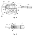
- Figure 2 shows the receptacle 10 of the present invention incorporated into a cardiac pacemaker having a housing 80, electronic circuits 82 and a power supply in the form of a battery 84.
- Conductors 86 and 88 connect the electronic circuits 82 to the receptacle pin terminal 20 and ring terminal 24, respectively.
- Figure 2 also compares the envelope of the housing 80 with that of a housing 80' of a pacemaker utilising a standard VS-1 connector system.
- a standard system shown in phantom in Figure 2 for comparison purposes, includes a pin 90 projecting from the tip of the pacing lead along with a mating socket 92 for receiving the pin. It will thus be seen that the receptacle 10 of the present invention is substantially shorter than that of the VS-1 system making possible a substantial reduction in the overall width of the pacemaker housing.
- the pacing lead 14 of the present invention can be adapted to be compatible with an existing VS-1 pacemaker connector assembly.
- Figure 3 shows an adapter terminal 94 having a projecting tip electrode 96 conforming to VS-1 standard dimensions and a pin 98 received by the pin socket 50 in the end of the pacing lead.
- the pin 98 may be provided with an annular groove 100 for mating with the garter spring contact 60.
- the adapter terminal 94 may also include an axially extending passageway 102 through which a stylet guide wire may be temporarily inserted.
Landscapes
- Health & Medical Sciences (AREA)
- Engineering & Computer Science (AREA)
- Biomedical Technology (AREA)
- Nuclear Medicine, Radiotherapy & Molecular Imaging (AREA)
- Radiology & Medical Imaging (AREA)
- Life Sciences & Earth Sciences (AREA)
- Animal Behavior & Ethology (AREA)
- General Health & Medical Sciences (AREA)
- Public Health (AREA)
- Veterinary Medicine (AREA)
- Heart & Thoracic Surgery (AREA)
- Vascular Medicine (AREA)
- Cardiology (AREA)
- Electrotherapy Devices (AREA)
Applications Claiming Priority (2)
| Application Number | Priority Date | Filing Date | Title |
|---|---|---|---|
| US07/940,567 US5324311A (en) | 1992-09-04 | 1992-09-04 | Coaxial bipolar connector assembly for implantable medical device |
| US940567 | 1992-09-04 |
Publications (2)
| Publication Number | Publication Date |
|---|---|
| EP0587379A2 true EP0587379A2 (fr) | 1994-03-16 |
| EP0587379A3 EP0587379A3 (fr) | 1994-12-28 |
Family
ID=25475064
Family Applications (1)
| Application Number | Title | Priority Date | Filing Date |
|---|---|---|---|
| EP93306968A Withdrawn EP0587379A3 (fr) | 1992-09-04 | 1993-09-03 | Connecteur bipolaire coaxial pour dispositif médical implantable. |
Country Status (4)
| Country | Link |
|---|---|
| US (1) | US5324311A (fr) |
| EP (1) | EP0587379A3 (fr) |
| JP (1) | JPH06190060A (fr) |
| AU (1) | AU661642B2 (fr) |
Cited By (11)
| Publication number | Priority date | Publication date | Assignee | Title |
|---|---|---|---|---|
| US5755743A (en) * | 1996-06-05 | 1998-05-26 | Implex Gmbh Spezialhorgerate | Implantable unit |
| WO1998042408A1 (fr) * | 1997-03-25 | 1998-10-01 | Pacesetter Ab | Boitier de stimulateur cardiaque |
| WO2000064535A1 (fr) * | 1999-04-26 | 2000-11-02 | Advanced Neuromodulation Systems, Inc. | Connecteur de derivation |
| US6755694B2 (en) | 2001-04-19 | 2004-06-29 | Medtronic, Inc. | Lead upsizing sleeve |
| US6921295B2 (en) | 2001-04-19 | 2005-07-26 | Medtronic, Inc. | Medical lead extension and connection system |
| WO2005077453A3 (fr) * | 2004-02-09 | 2005-11-10 | Cardiac Pacemakers Inc | Cable psa et connecteur de borne conductrice quadripolaire |
| US7287995B2 (en) | 2001-02-21 | 2007-10-30 | Stein Paul M | Medical lead and lead connector system |
| WO2010034343A1 (fr) * | 2008-09-24 | 2010-04-01 | Neurotech | Ensemble connecteur électrique hyperboloïde |
| US7753696B2 (en) | 2005-05-12 | 2010-07-13 | Cardiac Pacemakers, Inc. | Lead terminal multi-tool |
| WO2014143460A1 (fr) * | 2013-03-12 | 2014-09-18 | Cardiac Pacemakers, Inc. | Dispositif médical implantable et son ensemble |
| EP2265166B1 (fr) * | 2008-03-25 | 2020-08-05 | EBR Systems, Inc. | Connexion d électrode temporaire pour des systèmes de stimulation sans fil |
Families Citing this family (48)
| Publication number | Priority date | Publication date | Assignee | Title |
|---|---|---|---|---|
| JPH01280252A (ja) * | 1988-05-02 | 1989-11-10 | P C C Technol:Kk | イムノアッセイによる配糖化した低分子化合物の検出方法 |
| US5658171A (en) * | 1995-10-27 | 1997-08-19 | The Whitaker Corporation | Sealed coaxial feedthrough connector |
| US6238389B1 (en) * | 1997-09-30 | 2001-05-29 | Boston Scientific Corporation | Deflectable interstitial ablation device |
| SE9802928D0 (sv) | 1998-08-31 | 1998-08-31 | Pacesetter Ab | Device in connection with pacers I |
| US6039685A (en) * | 1998-09-14 | 2000-03-21 | St. Croix Medical, Inc. | Ventable connector with seals |
| SE9803692D0 (sv) | 1998-10-27 | 1998-10-27 | Pacesetter Ab | A connector for a heart stimulator |
| SE9803693D0 (sv) | 1998-10-27 | 1998-10-27 | Pacesetter Ab | Device in connection with pacers |
| US6327502B1 (en) * | 1999-08-16 | 2001-12-04 | Pacesetter Ab | Implantable stimulator housing with electrode connector |
| SE0000779D0 (sv) * | 2000-03-08 | 2000-03-08 | Pacesetter Ab | Process in connection with pacers |
| US6356778B1 (en) * | 2000-03-08 | 2002-03-12 | Ge Medical Systems Information Technologies, Inc. | Connector assembly for fetal scalp electrode |
| US6517476B1 (en) * | 2000-05-30 | 2003-02-11 | Otologics Llc | Connector for implantable hearing aid |
| US6714809B2 (en) * | 2000-11-20 | 2004-03-30 | Surgi-Vision, Inc. | Connector and guidewire connectable thereto |
| US6985775B2 (en) * | 2002-01-29 | 2006-01-10 | Medtronic, Inc. | Method and apparatus for shunting induced currents in an electrical lead |
| US6895276B2 (en) * | 2002-02-28 | 2005-05-17 | Medtronic, Inc. | In-line lead header for an implantable medical device |
| US7010355B2 (en) * | 2002-03-15 | 2006-03-07 | Medtronic, Inc. | Method and apparatus for connecting various implantable medical treatment system component devices |
| SE0201322D0 (sv) * | 2002-04-30 | 2002-04-30 | St Jude Medical | Device in connection with pacers |
| US7047077B2 (en) * | 2002-08-16 | 2006-05-16 | Cardiac Pacemakers, Inc. | Connector port construction technique for implantable medical device |
| US7035689B1 (en) * | 2002-10-14 | 2006-04-25 | Pacesetter, Inc. | Connector and retention mechanism for an implantable medical device |
| US7299095B1 (en) * | 2003-12-17 | 2007-11-20 | Pacesetter, Inc. | Electrical contact assembly |
| WO2006044539A2 (fr) * | 2004-10-18 | 2006-04-27 | Bal Seal Engineering Co., Inc. | Contacts ressort en tire-bouchon pour dispositif medicaux implantables |
| US7822479B2 (en) * | 2008-01-18 | 2010-10-26 | Otologics, Llc | Connector for implantable hearing aid |
| WO2011017432A1 (fr) | 2009-08-05 | 2011-02-10 | Medtronic, Inc. | Ensembles de connecteurs et de contacts pour dispositifs médicaux |
| WO2012155189A1 (fr) | 2011-05-13 | 2012-11-22 | National Ict Australia Ltd | Méthode et appareil d'estimation du recrutement neuronal-f |
| JP6096759B2 (ja) | 2011-05-13 | 2017-03-15 | サルーダ・メディカル・ピーティーワイ・リミテッド | 神経応答の測定のための方法および装置 |
| WO2012155185A1 (fr) | 2011-05-13 | 2012-11-22 | National Ict Australia Ltd | Méthode et appareil de mesure de la réponse neuronale |
| US10588524B2 (en) | 2011-05-13 | 2020-03-17 | Saluda Medical Pty Ltd | Method and apparatus for measurement of neural response |
| US9872990B2 (en) | 2011-05-13 | 2018-01-23 | Saluda Medical Pty Limited | Method and apparatus for application of a neural stimulus |
| US9386967B2 (en) | 2012-07-31 | 2016-07-12 | St. Jude Medical, Atrial Fibrillation Division, Inc. | Magnetic field-compatible components of a medical diagnostic and/or therapeutic system |
| AU2013344311B2 (en) | 2012-11-06 | 2017-11-30 | Saluda Medical Pty Ltd | Method and system for controlling electrical conditions of tissue |
| ES2836792T3 (es) | 2012-11-06 | 2021-06-28 | Saluda Medical Pty Ltd | Sistema para controlar las condiciones eléctricas de un tejido |
| AU2014351064B2 (en) | 2013-11-15 | 2019-07-04 | Closed Loop Medical Pty Ltd | Monitoring brain neural potentials |
| CA2929874C (fr) | 2013-11-22 | 2023-06-13 | Saluda Medical Pty Ltd | Procede et dispositif de detection d'une reponse neurale dans une mesure neurale |
| WO2015143509A1 (fr) | 2014-03-28 | 2015-10-01 | Saluda Medical Pty Ltd | Évaluation de l'état neuronal à partir de potentiels d'action |
| WO2015168735A1 (fr) | 2014-05-05 | 2015-11-12 | Saluda Medical Pty Ltd | Mesure neuronale amelioree |
| DK3171929T3 (da) | 2014-07-25 | 2021-05-25 | Saluda Medical Pty Ltd | Dosering til nervestimulation |
| AU2015349614B2 (en) | 2014-11-17 | 2020-10-22 | Saluda Medical Pty Ltd | Method and device for detecting a neural response in neural measurements |
| US10588698B2 (en) | 2014-12-11 | 2020-03-17 | Saluda Medical Pty Ltd | Implantable electrode positioning |
| EP3218046B1 (fr) | 2014-12-11 | 2024-04-17 | Saluda Medical Pty Ltd | Dispositif et programme informatique pour la commande de rétroaction de stimulation neuronale |
| WO2016100498A1 (fr) | 2014-12-17 | 2016-06-23 | Heartware, Inc. | Raccord implantable |
| AU2016208972B2 (en) | 2015-01-19 | 2021-06-24 | Saluda Medical Pty Ltd | Method and device for neural implant communication |
| WO2016161484A2 (fr) | 2015-04-09 | 2016-10-13 | Saluda Medical Pty Ltd | Estimation de distance électrode-nerf |
| WO2016191807A1 (fr) | 2015-05-31 | 2016-12-08 | Saluda Medical Pty Ltd | Fixation d'électrode de neurostimulateur cérébral |
| CA2983336C (fr) | 2015-05-31 | 2024-05-28 | Saluda Medical Pty Ltd | Surveillance de l'activite neurale du cerveau |
| JP7204325B2 (ja) | 2015-06-01 | 2023-01-16 | クローズド・ループ・メディカル・ピーティーワイ・リミテッド | 運動線維ニューロモジュレーション |
| US11191966B2 (en) | 2016-04-05 | 2021-12-07 | Saluda Medical Pty Ltd | Feedback control of neuromodulation |
| EP3474747B1 (fr) | 2016-06-24 | 2026-04-22 | Saluda Medical Pty Ltd | Stimulation neurale pour un artéfact réduit |
| US11040210B2 (en) | 2018-04-02 | 2021-06-22 | Pacesetter, Inc. | All metal enclosed implantable medical device with external BLE antenna for RF telemetry |
| EP4434461A3 (fr) | 2018-04-27 | 2025-03-05 | Saluda Medical Pty Ltd | Neurostimulation de nerfs mixtes |
Family Cites Families (15)
| Publication number | Priority date | Publication date | Assignee | Title |
|---|---|---|---|---|
| US3302159A (en) * | 1964-08-11 | 1967-01-31 | Amp Inc | Pluggable electrical connectors |
| US4387727A (en) * | 1981-03-30 | 1983-06-14 | Medtronic, Inc. | Coaxial service kit |
| US4782836A (en) * | 1984-05-24 | 1988-11-08 | Intermedics, Inc. | Rate adaptive cardiac pacemaker responsive to patient activity and temperature |
| US4764132A (en) * | 1986-03-28 | 1988-08-16 | Siemens-Pacesetter, Inc. | Pacemaker connector block for proximal ring electrode |
| US4848346A (en) * | 1987-12-02 | 1989-07-18 | Siemens-Pacesetter, Inc. | Pacemaker connector system |
| US4934367A (en) * | 1988-04-22 | 1990-06-19 | Medtronic, Inc. | In-line pacemaker connector system |
| US4934366A (en) * | 1988-09-01 | 1990-06-19 | Siemens-Pacesetter, Inc. | Feedthrough connector for implantable medical device |
| FR2642232B1 (fr) * | 1989-01-20 | 1993-09-03 | Alliance Tech Ind | Interface de connexion ultra miniature pour haute frequence |
| US4951687A (en) * | 1989-01-31 | 1990-08-28 | Medtronic, Inc. | Medical electrical lead connector |
| US4963105A (en) * | 1989-03-03 | 1990-10-16 | Dynawave Incorporated | Electrical connector assembly |
| DE3914677A1 (de) * | 1989-05-03 | 1990-11-08 | Alt Eckhard | Elektrische verbindungsvorrichtung zur herstellung von mechanischen und elektrischen verbindungen zwischen einem implantierbaren medizinischen geraet und einem zuleitungssystem |
| EP0448760A1 (fr) * | 1990-03-29 | 1991-10-02 | Siemens-Elema AB | Connexion électrique à fiche |
| US5076270A (en) * | 1990-05-03 | 1991-12-31 | Siemens-Pacesetter, Inc. | Apparatus and method for making electrical connections in an implantable pacemaker |
| US5012807A (en) * | 1990-05-03 | 1991-05-07 | Siemens-Pacesetter, Inc. | Multi-part molded pacemaker connector and method of making same |
| US5082453A (en) * | 1991-05-16 | 1992-01-21 | Siemens-Pacesetter, Inc. | Multi-contact connector system for an implantable medical device |
-
1992
- 1992-09-04 US US07/940,567 patent/US5324311A/en not_active Expired - Fee Related
-
1993
- 1993-09-01 AU AU46061/93A patent/AU661642B2/en not_active Ceased
- 1993-09-03 JP JP5243909A patent/JPH06190060A/ja active Pending
- 1993-09-03 EP EP93306968A patent/EP0587379A3/fr not_active Withdrawn
Cited By (16)
| Publication number | Priority date | Publication date | Assignee | Title |
|---|---|---|---|---|
| US5755743A (en) * | 1996-06-05 | 1998-05-26 | Implex Gmbh Spezialhorgerate | Implantable unit |
| WO1998042408A1 (fr) * | 1997-03-25 | 1998-10-01 | Pacesetter Ab | Boitier de stimulateur cardiaque |
| US6192276B1 (en) | 1997-03-25 | 2001-02-20 | Pacesetter Ab | Pacer housing |
| WO2000064535A1 (fr) * | 1999-04-26 | 2000-11-02 | Advanced Neuromodulation Systems, Inc. | Connecteur de derivation |
| US7287995B2 (en) | 2001-02-21 | 2007-10-30 | Stein Paul M | Medical lead and lead connector system |
| US6755694B2 (en) | 2001-04-19 | 2004-06-29 | Medtronic, Inc. | Lead upsizing sleeve |
| US6921295B2 (en) | 2001-04-19 | 2005-07-26 | Medtronic, Inc. | Medical lead extension and connection system |
| WO2005077453A3 (fr) * | 2004-02-09 | 2005-11-10 | Cardiac Pacemakers Inc | Cable psa et connecteur de borne conductrice quadripolaire |
| US7753696B2 (en) | 2005-05-12 | 2010-07-13 | Cardiac Pacemakers, Inc. | Lead terminal multi-tool |
| EP2265166B1 (fr) * | 2008-03-25 | 2020-08-05 | EBR Systems, Inc. | Connexion d électrode temporaire pour des systèmes de stimulation sans fil |
| WO2010034343A1 (fr) * | 2008-09-24 | 2010-04-01 | Neurotech | Ensemble connecteur électrique hyperboloïde |
| US8700160B2 (en) | 2008-09-24 | 2014-04-15 | Sorin Crm S.A.S. | Hyperboloid electrical connector assembly |
| WO2014143460A1 (fr) * | 2013-03-12 | 2014-09-18 | Cardiac Pacemakers, Inc. | Dispositif médical implantable et son ensemble |
| AU2017202387B2 (en) * | 2013-03-12 | 2018-10-04 | Cardiac Pacemakers, Inc. | Implantable medical device and assembly thereof |
| US10173053B2 (en) | 2013-03-12 | 2019-01-08 | Cardiac Pacemakers, Inc. | Implantable medical device and assembly thereof |
| EP3446748A1 (fr) * | 2013-03-12 | 2019-02-27 | Cardiac Pacemakers, Inc. | Dispositif médical implantable et son ensemble |
Also Published As
| Publication number | Publication date |
|---|---|
| EP0587379A3 (fr) | 1994-12-28 |
| JPH06190060A (ja) | 1994-07-12 |
| AU661642B2 (en) | 1995-07-27 |
| US5324311A (en) | 1994-06-28 |
| AU4606193A (en) | 1994-03-10 |
Similar Documents
| Publication | Publication Date | Title |
|---|---|---|
| US5324311A (en) | Coaxial bipolar connector assembly for implantable medical device | |
| US7299095B1 (en) | Electrical contact assembly | |
| US6096069A (en) | Medical electrical lead with conductors coiled around an inner tube | |
| US5906634A (en) | Implantable device having a quick connect mechanism for leads | |
| US4236525A (en) | Multiple function lead assembly | |
| US7242987B2 (en) | Medical lead adaptor | |
| US5304219A (en) | Multipolar in-line proximal connector assembly for an implantable stimulation device | |
| US5509928A (en) | Internally supported self-sealing septum | |
| US6671553B1 (en) | Implantable cardiac lead having terminating connector strain relief and method of manufacture | |
| US5086773A (en) | Tool-less pacemaker lead assembly | |
| US20230001214A1 (en) | Implantable medical device with modular injection molded header assembly and related methods of manufacture | |
| US8019420B2 (en) | Medical lead connector systems with adapters | |
| US5620477A (en) | Pulse generator with case that can be active or inactive | |
| EP1663390B1 (fr) | Gaines de connecteur de conducteur de derivation medical implantable | |
| USRE31990E (en) | Multiple function lead assembly and method for inserting assembly into an implantable tissue stimulator | |
| US12364866B2 (en) | Biostimulator header assembly having integrated antenna | |
| CA2736204C (fr) | Ensemble connecteur electrique hyperboloide | |
| GB2127629A (en) | Implantable medical device with sealed electrical coupling | |
| US4971057A (en) | Electrical connecting means for establishing mechanical and electrical connections between an implantable medical device and a lead system | |
| EP1644080B1 (fr) | Adaptateur de fil medical | |
| CN114206434B (zh) | 限定引线孔和装置隔室的医疗装置外壳 | |
| RU2177808C1 (ru) | Адаптер-переходник для подключения монополярного кардиоэлектрода к кардиостимулятору | |
| GB1598793A (en) | Cardiac pacemakers | |
| EP1795224A1 (fr) | Connecteur électrique pour dispositif médical implantable |
Legal Events
| Date | Code | Title | Description |
|---|---|---|---|
| PUAI | Public reference made under article 153(3) epc to a published international application that has entered the european phase |
Free format text: ORIGINAL CODE: 0009012 |
|
| AK | Designated contracting states |
Kind code of ref document: A2 Designated state(s): CH DE DK FR GB IT LI NL SE |
|
| PUAL | Search report despatched |
Free format text: ORIGINAL CODE: 0009013 |
|
| AK | Designated contracting states |
Kind code of ref document: A3 Designated state(s): CH DE DK FR GB IT LI NL SE |
|
| RAP1 | Party data changed (applicant data changed or rights of an application transferred) |
Owner name: PACESETTER AB |
|
| 17P | Request for examination filed |
Effective date: 19950628 |
|
| RAP1 | Party data changed (applicant data changed or rights of an application transferred) |
Owner name: PACESETTER, INC. |
|
| 17Q | First examination report despatched |
Effective date: 19981009 |
|
| STAA | Information on the status of an ep patent application or granted ep patent |
Free format text: STATUS: THE APPLICATION HAS BEEN WITHDRAWN |
|
| 18W | Application withdrawn |
Withdrawal date: 19990218 |