EP0587385B1 - Appareil d'impression et méthode pour la charge d'une batterie dans celui-ci - Google Patents
Appareil d'impression et méthode pour la charge d'une batterie dans celui-ci Download PDFInfo
- Publication number
- EP0587385B1 EP0587385B1 EP93307002A EP93307002A EP0587385B1 EP 0587385 B1 EP0587385 B1 EP 0587385B1 EP 93307002 A EP93307002 A EP 93307002A EP 93307002 A EP93307002 A EP 93307002A EP 0587385 B1 EP0587385 B1 EP 0587385B1
- Authority
- EP
- European Patent Office
- Prior art keywords
- battery
- printing
- motor
- ink
- charging
- Prior art date
- Legal status (The legal status is an assumption and is not a legal conclusion. Google has not performed a legal analysis and makes no representation as to the accuracy of the status listed.)
- Expired - Lifetime
Links
- 238000007639 printing Methods 0.000 title claims abstract description 145
- 238000000034 method Methods 0.000 title claims abstract description 53
- 238000007599 discharging Methods 0.000 claims description 6
- 230000004044 response Effects 0.000 claims description 6
- 238000009835 boiling Methods 0.000 claims description 5
- 230000003446 memory effect Effects 0.000 abstract description 9
- 239000000976 ink Substances 0.000 description 37
- 238000012545 processing Methods 0.000 description 36
- 238000007641 inkjet printing Methods 0.000 description 35
- 238000010586 diagram Methods 0.000 description 12
- 230000007423 decrease Effects 0.000 description 10
- 230000001133 acceleration Effects 0.000 description 9
- 239000012530 fluid Substances 0.000 description 8
- 238000010276 construction Methods 0.000 description 6
- 230000004048 modification Effects 0.000 description 5
- 238000012986 modification Methods 0.000 description 5
- 238000001514 detection method Methods 0.000 description 4
- 230000007704 transition Effects 0.000 description 3
- 101100084040 Neurospora crassa (strain ATCC 24698 / 74-OR23-1A / CBS 708.71 / DSM 1257 / FGSC 987) ppi-1 gene Proteins 0.000 description 2
- 230000005540 biological transmission Effects 0.000 description 2
- 230000008859 change Effects 0.000 description 2
- 239000003086 colorant Substances 0.000 description 2
- 230000008602 contraction Effects 0.000 description 2
- 230000001276 controlling effect Effects 0.000 description 2
- 230000006870 function Effects 0.000 description 2
- 239000007788 liquid Substances 0.000 description 2
- 230000007246 mechanism Effects 0.000 description 2
- 238000004904 shortening Methods 0.000 description 2
- 239000007787 solid Substances 0.000 description 2
- 238000013459 approach Methods 0.000 description 1
- 230000008901 benefit Effects 0.000 description 1
- OJIJEKBXJYRIBZ-UHFFFAOYSA-N cadmium nickel Chemical compound [Ni].[Cd] OJIJEKBXJYRIBZ-UHFFFAOYSA-N 0.000 description 1
- 238000009833 condensation Methods 0.000 description 1
- 230000005494 condensation Effects 0.000 description 1
- 238000001035 drying Methods 0.000 description 1
- 230000009977 dual effect Effects 0.000 description 1
- 239000000428 dust Substances 0.000 description 1
- 230000000694 effects Effects 0.000 description 1
- 238000001704 evaporation Methods 0.000 description 1
- 230000008020 evaporation Effects 0.000 description 1
- 230000005284 excitation Effects 0.000 description 1
- 238000010438 heat treatment Methods 0.000 description 1
- 238000012544 monitoring process Methods 0.000 description 1
- 230000002093 peripheral effect Effects 0.000 description 1
- 230000002035 prolonged effect Effects 0.000 description 1
- 230000001105 regulatory effect Effects 0.000 description 1
- 229920002379 silicone rubber Polymers 0.000 description 1
- 239000004945 silicone rubber Substances 0.000 description 1
- 239000000758 substrate Substances 0.000 description 1
Images


Classifications
-
- B—PERFORMING OPERATIONS; TRANSPORTING
- B41—PRINTING; LINING MACHINES; TYPEWRITERS; STAMPS
- B41J—TYPEWRITERS; SELECTIVE PRINTING MECHANISMS, i.e. MECHANISMS PRINTING OTHERWISE THAN FROM A FORME; CORRECTION OF TYPOGRAPHICAL ERRORS
- B41J29/00—Details of, or accessories for, typewriters or selective printing mechanisms not otherwise provided for
- B41J29/38—Drives, motors, controls or automatic cut-off devices for the entire printing mechanism
- B41J29/393—Devices for controlling or analysing the entire machine ; Controlling or analysing mechanical parameters involving printing of test patterns
-
- Y—GENERAL TAGGING OF NEW TECHNOLOGICAL DEVELOPMENTS; GENERAL TAGGING OF CROSS-SECTIONAL TECHNOLOGIES SPANNING OVER SEVERAL SECTIONS OF THE IPC; TECHNICAL SUBJECTS COVERED BY FORMER USPC CROSS-REFERENCE ART COLLECTIONS [XRACs] AND DIGESTS
- Y10—TECHNICAL SUBJECTS COVERED BY FORMER USPC
- Y10S—TECHNICAL SUBJECTS COVERED BY FORMER USPC CROSS-REFERENCE ART COLLECTIONS [XRACs] AND DIGESTS
- Y10S320/00—Electricity: battery or capacitor charging or discharging
- Y10S320/18—Indicator or display
- Y10S320/19—Charger status, e.g. voltmeter
Definitions
- This invention relates to a printing apparatus driven by a battery and to a method of charging the battery.
- a printing apparatus such as a printer or facsimile machine
- the energy driving element of a recording head is driven based upon image information that has been transferred thereto, whereby an image comprising a dot pattern is printed on a recording sheet such as paper or a thin plastic substrate.
- a printing apparatus of this kind can be classified into a number of types, such as an ink-jet type, wire-dot type and thermal type.
- a commercial power supply generally is used as the main power source.
- a dual power supply arrangement is adopted in which power is capable of being supplied by an AC adapter as well as by a battery.
- the printing apparatus is driven by a battery, it is difficult to drive the components of the apparatus when the output voltage of the battery becomes too low owing to a decline in the residual capacity of the battery. For example, if the printing function ceases owing to a decline in battery voltage during the course of a printing operation, all of the printing information received up to this point vanishes.
- a printing apparatus especially an ink-jet printing apparatus
- a widely employed technique is to make use of a discharge characteristic in which battery voltage declines with a decrease in battery capacity, with the battery capacity being estimated by detecting the battery voltage.
- the conventional practice is to detect battery voltage and, when the battery voltage falls below a specific voltage, suspend the operation of the apparatus upon determining that the battery capacity is inadequate. The operator is notified of the lack of battery capacity by an indicating element such as a buzzer or lamp.
- a printing apparatus such as a serial printer
- the printing head is mounted on a carriage driven back and forth horizontally by a carriage motor.
- the recording medium on the other hand, is conveyed at right angles to the back-and-forth traveling direction of the carriage by conveyor rollers driven by a paper-feed motor.
- Fig. 8 is a diagram showing the drive timing of the carriage motor and the drive timing of the paper-feed motor.
- the amount of power consumed during a printing operation is maximum in an interval over which decelerating drive of the carriage motor and accelerating drive of the paper-feed motor overlap, as well as in an interval over which decelerating drive of the paper-feed motor and accelerating drive of the carriage motor overlap (both intervals are indicated by X).
- the amount of power consumed in these intervals attains a value more than twice that of average power consumption during an ordinary printing operation.
- NiCd nickel-cadmium
- a nickel-cadmium (NiCd) battery generally is well known as a large-capacity secondary battery that is capable of being charged. It is known that when a battery of this kind has its final discharge voltage set to a high voltage value of more than 1.1 V/cell and is repeatedly charged and discharged, there is a decline in the discharge capacity or discharge voltage. This phenomenon is known as the "memory effect". This phenomenon will not occur if the battery is charged following discharge to a final discharge voltage of 1.0 V/cell, which is specific to an NiCd battery. In addition, even an NiCd battery in which the memory effect has appeared is capable of being almost fully restored to its original discharge capability.
- a method considered as a countermeasure is to forcibly discharge the remaining capacity of the battery, before charging starts, until the final discharge voltage of the NiCd battery is attained, and then perform charging.
- a special-purpose discharge circuit for discharging the battery is required. The result is higher cost.
- such forcible discharging requires 30 minutes to one hour, the total charging time is prolonged.
- JP-A-4-85045 discloses an ink-jet printer having a carriage motor and a conveyance motor which are driven together such that one of the motors is caused to accelerate during the deceleration of the other motor, so that both motors are driven together during an overlap period.
- the ink-jet printer also has an ink heater for heating the ink prior to discharge through associated discharge ports.
- JP-A-4-85045 discloses varying the timing at which the carriage motor and the conveyance motor are driven and the timing at which the heater is operated, so that only two operate at any one time, thereby preventing excessive power drainage from the power source.
- the present invention provides a printing apparatus operable under power, comprising: a carriage motor for conveying a printing head; a conveyance motor for conveying a printing medium; and drive means for commencing and terminating the driving of said conveyance motor and said carriage motor, said drive means being operable to cause one of said motors to accelerate during deceleration of the other motor so that both motors are driven together during an overlap period; wherein: said printing apparatus is operable under power from a battery; detecting means is provided for detecting the remaining capacity of the battery; and control means responsive to the remaining battery capacity detected by said detecting means is provided, which control means is operable to control said drive means such that said overlap period is removed when the remaining battery capacity detected by said detecting means falls below a predetermined value.
- the present invention provides a method of controlling the driving of motors in a printing apparatus driven by a supply of electric power from a battery, said printing apparatus having a carriage motor for conveying a printing head and a conveyance motor for conveying the printing medium relative to the printing head, the method comprising the steps of: commencing and terminating the driving of said conveyance motor and said carriage motor such that one of said motors is accelerated during a deceleration of the other motor so that both motors are driven together during an overlap period; the method comprising also the steps of: providing electric power by means of a battery; detecting the remaining capacity of the battery; and controlling the driving of said conveyance motor and said carriage motor such that said overlap period is removed when the remaining battery capacity detected in said detecting step falls below a predetermined value.
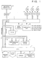
- Fig. 1 is a block diagram illustrating the general configuration of the principal portion of an ink-jet printing apparatus according to a first embodiment of the present invention.
- the printing apparatus described will be of the ink-jet type.
- the invention is not limited to this arrangement and is applicable not only to a printing apparatus using another recording method but also to the printing apparatus of a word processor or facsimile machine.
- the apparatus shown in Fig. 1 includes a programmable peripheral interface (hereinafter referred to as a "PPI") 1 for receiving a command signal or recording-information signal, which is sent from a host computer (not shown), and transferring the received signal to an a microprocessing unit (hereinafter referred to as an "MPU") 2.
- the PPI 1 also exchanges control signals with a console 6 and receives, as an input, a signal from a home-position sensor 7, which senses that a carriage is at the home position.
- the MPU 2 controls the components of the ink-jet printing apparatus in accordance with a control program stored in a control ROM 5.
- a RAM 3 stores a received signal or is used as the work area of the MPU 2 for the purpose of temporarily storing various data.
- a ROM 4 for generating fonts stores pattern information such as characters and symbols in correspondence with code information. In response to an input of code information, the ROM 4 outputs the corresponding pattern information.
- a ROM 5 for control stores processing procedures (Figs. 4 ⁇ 7) executed by the MPU 2. These components are controlled by the MPU 2 via an address bus 17 and a data bus 18.
- a carriage motor 8 moves a carriage 30 (see Fig. 2), on which a printing head 12 is mounted, in such a manner that the carriage 30 is made to scan back and forth.
- a paper-feed motor 10 is for conveying a recording medium such as paper at right angles to the direction in which the carriage 30 is moved.
- a capping motor 13 drives a cap portion 32A (see Fig. 2) in such a manner that the cap portion 32A is brought into contact with an ink jetting port (not shown) of the printing head 12, described below, thereby closing the port off from the outside air to prevent the nozzle from drying out.
- Motor drivers 14, 15 and 16 drive the capping motor 13, the carriage motor 8 and the paper-feed motor 10, respectively.
- the console 6 is provided with keyboard switches, display lamps and the like.
- the home-position sensor 7 is provided in close proximity to the home position of the carriage 30 and senses when the carriage, on which the printing head 12 is mounted, has arrived at the home position.
- a sheet sensor 9 senses the presence of the recording medium, such as recording paper. More specifically, the sensor 9 senses whether the recording medium has been supplied to the recording section of the apparatus.
- the ink-jet printing head 12 is provided with a jetting port and a jetting motor, neither of which are shown.
- a driver 11 drives the jetting motor of the printing head 12 in accordance with the printing information signal.
- a power-supply unit 24 supplies each of the above-mentioned components with power and has an AC adapter and a battery as driving power-supply devices.
- the MPU 2 is connected to a host apparatus such as a computer via the PPI 1 and controls the printing operation based upon the command and printing information signal sent from the host apparatus, the processing procedure of the program stored in the control ROM 5 and the printing information stored in the RAM 3.
- Fig. 2 is a perspective view showing the construction of the printing unit constituting the ink-jet printing apparatus of this embodiment.
- the ink-jet printing head 12 is mounted on the carriage 30 in combination with an ink-jet cartridge capable of being attached to and detached from the carriage 30 through a prescribed method.
- One or more of the ink-jet cartridges may be provided in accordance with the inks used in printing.
- the head 12 is provided with an ink tank and an ink sensor, which are not shown.
- the printing head 12 is supplied, via the driver 11, with an ink jetting signal conforming to printing data from a data supply source arriving via a cable and a terminal connected thereto.
- the carriage 30 is coupled to part of a driving belt 33, which transmits the driving force of the carriage motor 8, and is capable of being slid along two parallel, side-by-side guide shafts 31A, 31B, whereby the printing head 12 is capable of being moved back and forth along the entire width of the recording medium.
- the relative movement between the carriage 30 and the recording medium is controlled by an input of a prescribed printing signal, whereby a desired image is printed on the recording surface of the recording medium, which has been conveyed to a platen 35 from a paper-feed unit 34.
- a head restoration unit 32 is disposed at one end of the path of travel of the printing head 12, e.g., at a location opposing the home position.
- the head restoration unit 32 is operated, through the intermediary of a transmission mechanism 36, by the driving force of the capping motor 13 so as to cap the printing head 12.
- jetting restoration processing is executed.
- an ink sucking operation is performed by suitable suction means provided within the head restoration unit 32 or an ink pressure-feed operation is performed by suitable pressurizing means provided in an ink supply passage leading to the printing head 12, as a result of which the ink is forcibly discharged from the ink jetting port to clear highly viscous ink from the ink passageways. Further, at the end of the printing operation, the ink-jetting printer head 12 is capped to protect the head.
- Numeral 37 denotes a plate, which consists of silicone rubber or the like, disposed on the side face of the head restoration unit 32 so as to serve as a wiping member.
- the plate 37 is held in a cantilevered state on a plate holding member 37A and is operated by the capping motor 13 and transmission mechanism 36 in the same manner as the head restoration unit 32 so as to be capable of engaging the jetting surface of the printing head 12.
- the plate 37 is projected into the traveling path of the printing head 12 to wipe off condensation, moisture and dust from the jetting surface of the printing head 12.
- the power-supply unit 24 further includes a supply changeover unit 21, which uses a power-supply jack or the like, for selecting either of these two driving power supplies, and a power-supply voltage detecting circuit 23 for detecting the output voltage of the driving power supply and sending an output signal to an input port.
- the detecting circuit employed has a simple construction in which voltage is divided by a resistor and then applied to the MPU 2.
- other possible arrangements include one employing an A/D converter and one using a comparator.
- the power-supply unit 24 further includes a power-supply circuit 22 for converting the DC output of the driving power supply to a voltage suitable for driving the components of the ink-jet printing apparatus.
- a logic voltage 1 is supplied to the MPU 2. This voltage is outputted even in a power-off mode.
- a logic voltage 2 is supplied to logic other than the MPU 2, e.g., the RAM 3; motor voltages are supplied to the motors 9, 10, 13; and a head voltage is supplied to the printing head 12. These voltages are applied only when power is on (in a printing standby state and a printing operating state).
- the printing operation is controlled based upon the results of sensing battery capacity. This control will now be described in general terms.
- the drive timings of the motors 8, 10 are changed if the battery capacity falls below that at which drive by the battery was suspended in the prior art, thereby avoiding overlapping of acceleration/deceleration of the carriage motor 8 and paper-feed motor 10 and allowing the printing operation to continue (see Fig. 9).
- the maximization of consumed current can be reduced by half. Consequently, since the duration of the drop in battery output voltage that occurs in this interval is reduced, the battery output voltage declines considerably and approaches the final discharge voltage, and the printing operation using the battery is capable of being continued immediately up to the point at which battery capacity is used up.
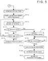
- Figs. 4 through 7 are flowcharts illustrating an example of the printing operation according to this embodiment. An overview of this processing is as follows: When the apparatus is driven by the battery, the capacity of the battery is sensed (steps S104, S105) immediately before cap removal processing (step S108) at a transition from the standby state to the start of printing in accordance with printing information from the host apparatus. The reason for this is to prevent the following problem: If battery capacity has fallen to a level at which drive of the carriage 30 and cap portion 32A cannot be assured, the apparatus will cease functioning, or one line will be printed, immediately after the ink jetting port is uncapped in order to start printing.
- step S133 Low battery power is then discriminated by a battery-capacity discrimination step (step S133), which is performed in synchronization with a deceleration pulse of the carriage motor 8, as will be described below. Accordingly, functioning of the apparatus stops without the carriage 30 being returned to the home position and without execution of the protecting operation in which the ink jetting port of the printing head 12 is sealed by the cap portion 32A. Thus, to prevent this from occurring, it is judged at steps S104, S105 whether the battery 20 has enough residual capacity necessary for returning the printing head 12 to the home position and for capping the ink jetting port after at least one line of printing.
- step S100 it is determined at step S100 whether a print-start request has been generated based upon printing information received from the host apparatus. If start of printing has not been requested, the program branches to steps from S122 onward, at which the system waits for the print-start request in a state in which the ink jetting port of the printing head 12 has been sealed by the cap portion 32A (steps S122 ⁇ S124).
- step S100 If a YES answer is obtained at step S100, then the printing operation is started by the procedure from step S101 onward. Specifically, it is determined at step S101 whether the ink jetting port has been capped by the cap portion 32A. If the jetting port is in the uncapped state, then the program proceeds to step S201. The processing from step S201 onward will be described later.
- step S101 When the capped state is found at step S101, i.e., when the carriage 30 is at the home position and the ink jetting port of the printing head 12 has been capped by the cap portion 32A, the program proceeds to step S102 and it is determined whether the paper-feed motor 10 is being driven. If the motor is being driven, the apparatus waits until drive ends. If the motor 10 is not being driven, however, then it is determined by the procedure of steps S103 ⁇ S107 whether the battery 20 has enough capacity to allow uncapping (this procedure is for sensing low-power error).
- a discharge load suitable for sensing capacity is applied to the battery 20 in order to sense the capacity of the battery 20 in an accurate manner.
- a discharge load suited to the battery 20 is applied by exciting the carriage motor 8 without changing its phase (this is referred to as "pseudo-excitation").
- step S104 the output voltage of the battery 20 is detected by the power-supply voltage detecting circuit 23 after elapse of time t 3 (e.g., 50 msec). If this operation has been repeated n times via step S105, the program proceeds to step S106, at which pseudo-excitation of the carriage motor 8 is terminated.
- step S107 it is determined at step S107 whether battery power is low (i.e., whether the output voltage of battery 20 is less than a predetermined value). More specifically, the average value of the battery voltage detected n times is calculated and the power of the battery is judged to be too low if the average value is less than a preset final discharge voltage. Otherwise, the battery power is not considered to be too low. It should be noted that the set value of final discharge voltage is stored in the control ROM 5 in advance.
- step S107 determines whether the battery power is not too low. If the determination made at step S107 is that the battery power is not too low, the program branches to step S108 (uncapping processing) and acceleration of the carriage motor 8 is started (step S109) after uncapping processing is executed. At the end of acceleration, one line is printed (step S110) while the carriage is moved at a constant speed (i.e., while the carriage motor 8 is rotatively driven at a constant speed), after which the program proceeds to step S125 (Fig. 6A).
- step S107 If battery power is found to be low at step S107, uncapping processing is canceled to prevent the ink jetting portion of the printing head 12 from being left open to the outside air. Further, protection of printing information already received is achieved by the procedure from step S111 onward. This processing will now be described.
- the apparatus is placed in the off-line state with respect to the host apparatus at step S111 and then a transition is made to a low-power error at step S112. That is, in the low-power error state, interrupt processing other than initiated by the power switch on the console 6 is inhibited and the operator is notified of the low-power error by alarm means such as a buzzer or LED. Control from step S113 onward is then executed. This will now be described.
- step S113 detection and decision operations are performed to determine whether the operator has connected the AC adapter 19 to the printing apparatus to restore the output voltage of the power supply. If the AC adapter 19 has been used to restore the power-supply voltage, the program branches to step S117, where the low-power error state is canceled. Here printing information from the host apparatus is not received in the off-line state, but printing information that has been received up to the moment of error generation and that has not yet been subjected to printing processing is held in the RAM 3. Accordingly, it is determined at step S118 whether the operator has performed an on-line operation to make possible the reception of data from the host apparatus.
- step S119 processing for restoring the apparatus to the on-line state with respect to the host apparatus is executed.
- step S120 processing for restoring the apparatus to the on-line state with respect to the host apparatus is executed.
- step S120 processing for restoring the apparatus to the on-line state with respect to the host apparatus is executed.
- step S120 the transition to the on-line state is made so that data from the host apparatus can be received.
- a return is made to processing that was suspended by generation of the low-power error. If there is printing information that has not yet been printed, processing for printing this information is started.
- steps S113 ⁇ S115 which are for determining whether the power-supply voltage has been restored within a fixed time t 2 (e.g., 5 min) from generation of the error, it is determined that the battery has been expended and power is turned off automatically at step S116 before the printing apparatus becomes uncontrollable.
- the foregoing is the control procedure from the state in which the ink jetting nozzle is capped to the start of printing in response to a print-start request.
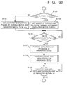
- this processing involves sensing the capacity of the battery 20 during printing, this being performed one time, whenever one line is printed, while the carriage motor 8 is being decelerated.
- the printing operation is controlled in two stages based upon the results of sensing the output voltage of the battery.
- the drive timings of the carriage motor 8 and paper-feed motor 10 are changed over in such a manner that the two motors will not be driven in overlapping fashion.
- a voltage drop due to the internal resistance of the battery 20 increases temporarily when the carriage motor 8 and paper-feed motor 10 are driven simultaneously. Consequently, even through depletion of battery capacity has not yet been attained, there is the possibility that system reset of the apparatus will be activated owing to the temporary drop in battery voltage, as a result of which the printing operation will cease with attendant loss of the printing information already received.
- the battery capacity is sensed in the interval during which power consumption of the apparatus is maximized, namely in the interval during which the carriage motor 8 and paper-feed motor 10 are driven in overlapping fashion, and a changeover is performed in such a manner that the driving operations of the motors 8 and 10 will not overlap (step S134).
- a state in which the battery voltage temporarily falls by a wide margin is suppressed so that the printing operation is allowed to continue. Accordingly, battery capacity can be fully exploited and drive by the battery can be performed for a longer period of time without increasing the capacity of the battery.
- the second stage battery capacity is sensed in a state in which the printing operation is performed without overlapping drive of the carriage motor 8 and paper-feed motor 10, and measures for protecting the apparatus (low-power error processing) are taken by interrupting the printing operation before the apparatus ceases functioning owing to depletion of the battery.
- drive of the carriage motor 8 and drive of the paper-feed motor 10 do not overlap, as mentioned above. Therefore, even though sensing of the capacity of battery 20 is performed during decelerated drive of the carriage motor 8 in the same manner as sensing of battery capacity in the first state, the drop in the battery voltage is reduced to half that in the first stage. In this embodiment, therefore, the reference voltage value for judging the capacity of the battery is the same value for both the first and second stages.
- step S125 decelerated drive of the carriage motor 8 is started at step S125.
- step S126 the program proceeds to step S126.
- the program proceeds to step S129.
- Step S129 calls for the system to wait until the number of remaining decelerated-drive pulses of the carriage motor 8 attains the preset number S (i.e., until the relation m ⁇ is attained).
- the program proceeds to step S130, where the battery capacity is sensed by detecting the power-supply voltage when there is a changeover in excitation phase of the carriage motor 8.
- step S132 the program proceeds to step S132, where it is determined whether the paper-feed motor 10 is being driven. If it is found that the paper-feed motor 10 is being driven, then the program proceeds to step S133.
- step S133 it is determined whether it is necessary to change the number of pulses of overlapping drive of the carriage motor 8 and paper-feed motor 10 in dependence upon the battery capacity sensed at steps S130, S131.
- step S132 When it is found at step S132 that the paper-feed motor 10 is not being driven, the program branches to step S140 (Fig. 7), where it is determined whether it is necessary to perform low-power error processing based upon the battery capacity sensed at steps S130, S131.
- step S133 onward Processing from step S133 onward for the case in which the paper-feed motor 10 is being driven will be described first.
- step S133 the program proceeds to step S135, at which the overlapping number of pulses is set to be equal to or greater than m (m ⁇ n ⁇ 0; where m, n are integers). If battery power is found to be too low at step S133, however, then the program proceeds to step S134, where by overlapping pulse number is set to zero.
- step S134 the program proceeds to steps S136, S137, where acceleration of the paper-feed motor 10 and constant-velocity operation are performed. Thereafter, decelerated rotation of the paper-feed motor 10 is started at step S138.
- step S139 it is determined whether the number of remaining pulses of decelerated drive of the paper-feed motor 10 has fallen below the number of overlapping pulses set at steps S134, S135. If the answer is YES, then the program returns to step S100 in Fig. 4 and the above-described processing is repeated.
- step S127 the program proceeds to step S204, at which it is determined whether the number of overlapping pulses is zero or not. When this number is not zero, the program proceeds to step S205, at which it is determined whether a number that agrees with a designated overlapping-pulse number has been attained. If the answer obtained here is YES, then the program proceeds to step S128, where acceleration of the paper-feed motor 10 is started. If the overlapping-pulse number is zero, however, the program proceeds to step S206, at which the aforesaid steps S129 ⁇ S131 are executed to detect the power-supply voltage.
- step S207 The system waits for the carriage motor 8 to stop rotating at step S207, after which it is determined at step S208 whether a power-supply voltage has been attained at which operation cannot be continued. If such is the case, then the program proceeds to step S141, where the carriage motor 8 is decelerated and rotation thereof halted. The off-line state also is established. If operation still cannot continue at step S208, the program proceeds to step S209, at which acceleration of the paper-feed motor 10 is started, in the same manner as at step S128, and then the program proceeds to step S133.
- step S201 determines whether the number of overlapping-pulse is zero or not. When this number is not zero, the program proceeds to step S203, at which it is determined whether or not a number agrees with the overlapping-pulse number. If the answer obtained here YES, the program proceeds to step S109, where acceleration of the carriage motor 8 is started. At step S201, if the overlapping-pulse number is zero, then the program proceeds to step S202, at which the system waits for the paper-feed motor 10 to stop rotating. After that, the program proceeds to step S109.
- step S140 the program proceeds to step S140, at which it is determined whether it is necessary to perform low-power error processing. If this processing is not necessary, then the program returns to step S100 of Fig. 4 so that the control procedure described thus far is repeated. If the low-power error processing is necessary, on the other hand, the program proceeds to step S141, where the system waits for the end of processing for decelerating the carriage motor 8. When this processing ends, low-power error processing is executed through a procedure from step S142 onward.
- step S142 The apparatus is put on line at step S142, the carriage 30 is returned to the home position at step S143 and the printing head 12 is capped at step S144. Since the control procedure of steps S145 ⁇ S154 is identical with the processing of steps S112 ⁇ S121 of Fig. 5 described above, this procedure need not be described again.
- Fig. 9 is a diagram schematically showing the drive timings of the carriage motor 8 and paper-feed motor 10 in a case where zero has been set as the number of overlapping pulses in the interval X in which drive of the carriage motor 8 and drive of the paper-feed motor 10 overlap.
- the printing operation is controlled in such a manner that the capacity of the power-supply battery can be fully exploited, thereby making it possible to prolong printing time by one and the same battery without inviting an increase in the cost of the apparatus.
- Fig. 10 is a block diagram illustrating the general configuration of an ink-jet printing apparatus according to a second embodiment of the present invention. Elements corresponding to those shown in Fig. 1 are designated by like reference characters and need not be described again.
- the apparatus shown in Fig. 10 includes loading resistors 201 ⁇ 203, and a switch 204 closed under control of an MPU 2a when the battery 20 is charged. With regard to the charging power at this time, electric power from the AC adapter 19 is converted by the power-supply circuit 22 and the converted power is supplied to the battery 20.
- the apparatus further includes an A/D converter 205, the input to which is the output voltage of the battery 20 voltage-divided by the loading resistors 202, 203, for A/D converting this input and delivering the resulting digital signal to the MPU 2a.
- the MPU 2a is capable of detecting the battery capacity of the battery 20.
- the apparatus is further provided with a user-operated switch 207 which, by being closed, commands the start of a charging operation, a switch 208 for setting the number of pages to be printed, and a display device (LED) for notifying the operator of the fact that the battery 20 has been charged enough to enable printing of the number of pages set by the switch 208.
- a user-operated switch 207 which, by being closed, commands the start of a charging operation
- a switch 208 for setting the number of pages to be printed
- a display device (LED) for notifying the operator of the fact that the battery 20 has been charged enough to enable printing of the number of pages set by the switch 208.
- the user employs the switch 208 to set the number of pages to be printed and then commands the start of charging by using the switch 207.
- the MPU 2a reads the number of pages set by the switch 208, refers to a ROM table 500 and obtains the battery charging level that conforms to the set number of pages.
- the MPU 2a then lights the LED 206 to inform of the fact that the charging operation has started, reads the digital data from the A/D converter 205 and determines whether the battery 20 has attained the prescribed voltage level. If the prescribed level has been attained, charging is unnecessary and processing is ended in this state.
- the MPU 2a closes the switch 204 to start the charging of the battery 20.
- the MPU 2a then reads the output value of the A/D converter 205 at fixed time intervals and determines whether the charging voltage of the battery 20 has attained a predetermined voltage value. If the voltage of battery 20 has attained the predetermined voltage value, the MPU 2a opens the switch 204, extinguishes the LED 206 and terminates charging processing.
- Fig. 11 is a flowchart showing the charging processing in the ink-jet printing apparatus according to the second embodiment.
- the control program for executing this processing is stored in a control ROM 5a in advance.
- This processing is initiated by pressing the switch 207 to enter a command for starting charging.
- the number of pages set by the switch 208 is entered at step S1, after which the charging voltage of the battery 20 corresponding to this number is found by referring to the ROM table 500.
- the program proceeds to step S3, at which the switch 204 is closed and the LED 206 is lit.
- the output of the A/D converter 205 is investigated at step S4, at which it is determined whether the charging voltage of the battery 20 has attained the prescribed voltage found at step S2. If the prescribed voltage has not been attained, the program proceeds to step S5, at which the system waits for elapse of a prescribed period of time before the program returns to step S4.
- step S4 If the prescribed voltage is attained at step S4, then the program proceeds to step S6, where the switch 204 is opened to end charging of the battery 20 and the LED 206 is extinguished to notify of the end of charging.
- the battery can be charged an amount commensurate with the number of pages desired to be printed out by the user. This has the effect of shortening charging waiting time.
- Another advantage of this embodiment is that depletion of the battery, which might otherwise occur during the printing of the desired number of pages, is prevented.
- Fig. 12 is a diagram showing a modification of the second embodiment, in which portions corresponding to those of the foregoing drawings are designated by like reference characters and need not be described again.
- the LED 206 is deleted.
- the battery 20 is charged to allow printing of the designated number of pages, the printable number of pages are printed out by the printing head 12.
- charging time is shortened and the user is capable of being informed of the number of printable pages in the same manner as set forth in the second embodiment.
- the MPU 2a instead of the LED 206 being extinguished at step S6 in the flowchart of Fig. 11, the MPU 2a refers to the charging voltage entered from the A/D converter 205 and the printable number of pages corresponding to this voltage value obtained from the ROM table 500, obtains the number of pages, generates the corresponding character patterns from the font generating ROM 4 and outputs these character patterns to the printing head 12.
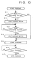
- the above-described memory effect of the battery is prevented.
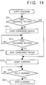
- the charging operation is performed after the battery fully attains the final discharge voltage, thereby preventing the decline in apparent battery capacity caused by the memory effect of the battery.
- This processing is started by commanding the start of charging of battery 20 by the switch 207. As shown in Fig. 13, it is determined at step S11, based upon the output of the A/D converter 205, whether the output voltage of the battery 20 has attained the final discharge voltage. If it has, the program proceeds to step S15 so that the charging is started as indicated by the flowchart of Fig. 11.
- step S11 If it is found at step S11 that the final discharge voltage has not been attained, then the program proceeds to step S12, where the carriage motor 8 is rotatively driven to consume the power of the battery 20. It is then determined at step S13 whether the voltage of the battery 20 has attained the final discharge voltage. If the final discharge voltage has been attained, the program proceeds to step S14, at which rotation of the carriage motor 8 is halted, and then to step S15, at which charging of the battery 20 is started. The output of the A/D converter 205 is examined at step S15 to determine whether the battery 20 has been charged sufficiently. If the answer is YES, then the program proceeds to step S17 and the charging operation is concluded.
- Fig. 14 is a flowchart illustrating charging processing similar to that of the flowchart of Fig. 13.
- the paper-feed motor 10 is driven instead of the carriage motor 8.
- charging of the battery is started after the battery has fully attained the final discharge voltage, this being accomplished without providing anew a discharge circuit for discharging the battery. This makes it possible to prevent the memory effect and fully exploit the battery.
- the battery is discharged by driving the carriage motor 8 and paper-feed motor 10.
- an arrangement may be adopted in which current is passed through a load that consumes a large amount of current, such as the printing head or head restoration device, to accomplish discharge of the battery.
- a recording apparatus is described that is one of the ink-jet types, in which means (e.g., an electrothermal transducer or laser beam, etc.) is provided for generating thermal energy as energy utilized in order to jet ink, wherein a change in the state of the ink is caused by the thermal energy.
- means e.g., an electrothermal transducer or laser beam, etc.
- thermal energy as energy utilized in order to jet ink, wherein a change in the state of the ink is caused by the thermal energy.
- a jetting port is made to jet the fluid (ink) by growth and contraction of the air bubbles so as to form at least one droplet.
- the drive signal has the form of a pulse, growth and contraction of the air bubbles can be made to take place rapidly and in appropriate fashion. This is preferred since it will be possible to achieve fluid (ink) jetting having excellent response.
- Signals described in the specifications of USP 4,463,359 and 4,345,262 are suitable as drive pulses having this pulse shape. It should be noted that even better recording can be performed by employing the conditions described in the specification of USP 4,313,124, which discloses an invention relating to the rate of increase in the temperature of the above-mentioned thermal working surface.
- the present invention covers also an arrangement using the art described in the specifications of USP 4,558,333 and 4,459,600, which disclose elements disposed in an area in which the thermal working portion is curved. Further, it is permissible to adopt an arrangement based upon Japanese Patent Application Laid-Open No. 59-123670, which discloses a configuration having a common slot for the jetting portions of a plurality of electrothermal transducers, or Japanese Patent Application Laid-Open No. 59-138461, which discloses a configuration having openings made to correspond to the jetting portions, wherein the openings absorb pressure waves of thermal energy.
- the present invention is effective also in a case in which use is made of a recording head secured to the main body of the apparatus even in the serial-type arrangement of the foregoing example; a freely exchangeable tip-type recording head attached to the main body of the apparatus and capable of being electrically connected to the main body of the apparatus and of supplying ink from the main body; or a cartridge-type recording head in which an ink tank is integrally provided on the recording head itself.
- the recording mode of the recording apparatus is not limited merely to a recording mode for a mainstream color only, such as the color black.
- the recording head can have a unitary construction or a plurality of recording heads can be combined.
- the invention is effective also in an apparatus having at least one recording mode for a plurality of different colors or for full-color recording using mixed colors.
- ink is described as being the fluid in the embodiments of the invention set forth above.
- the ink used may be one which solidifies at room temperature or lower, or one which softens of liquefies at room temperature.
- the ink is temperature-controlled by regulating the temperature of the ink itself within a temperature range of between 30°C and 70°C so that the viscosity of the ink will reside in a region that allows stable jetting of the ink. Therefore, it is permissible to use an ink liquefied when the recording signal is applied.
- an ink which solidifies when left standing but which liquefies when heated it is permissible to use an ink which solidifies when left standing but which liquefies when heated.
- the present invention is applicable also in a case where use is made of an ink which solidifies in response to application of thermal energy, such as an ink solidified by application of thermal energy conforming to a recording signal or ink which has already begun to solidify at the moment it reaches the recording medium.
- Such inks may be used in a form in which they oppose the electrothermal transducer in a state in which they are held as a liquid or solid in the recesses or through-holes of a porous sheet, as described in Japanese Patent Application Laid-Open Nos. 54-56847 and 60-71260.
- the most effective method of dealing with these inks is the above-described method of film boiling.
- the recording apparatus use is not limited to an image output terminal of an image processing apparatus such as a computer.
- Other configurations include a copying machine in combination with a reader or the like, a facsimile machine having a transmitting/receiving function, etc.
- the invention is applicable also to a case where the object of the invention is attained by supplying a program to a system or apparatus.
Landscapes
- Accessory Devices And Overall Control Thereof (AREA)
- Charge And Discharge Circuits For Batteries Or The Like (AREA)
- Tests Of Electric Status Of Batteries (AREA)
- Ink Jet (AREA)
- Character Spaces And Line Spaces In Printers (AREA)
- Secondary Cells (AREA)
Claims (18)
- Appareil d'impression pouvant être mis en fonctionnement par une alimentation électrique, comprenant :un moteur de chariot (8) pour transporter une tête d'impression (12) ;un moteur de transport (10) pour transporter un support d'impression ; etdes moyens d'entraínement (14, 15) pour commencer et terminer l'entraínement dudit moteur de transport et dudit moteur de chariot, lesdits moyens d'entraínement pouvant être mis en fonctionnement de façon à faire en sorte que l'un desdits moteurs accélère pendant la décélération de l'autre moteur afin que les deux moteurs soient entraínés en même temps pendant une période de chevauchement ;
caractérisé en ce queledit appareil d'impression peut être mis en fonctionnement en étant alimenté en électricité par une batterie ;des moyens de détection (23) sont prévus pour détecter la capacité restante de la batterie (20) ; etdes moyens de commande (2) sensibles à la capacité restante de la batterie détectée par lesdits moyens de détection (23) sont prévus, ces moyens de commande pouvant être mis en fonctionnement pour commander lesdits moyens d'entraínement (14, 15) de telle façon que ladite période de chevauchement soit éliminée lorsque la capacité restante de la batterie détectée par lesdits moyens de détection (23) s'abaisse en dessous d'une valeur prédéterminée. - Appareil selon la revendication 1, dans lequel lesdits moyen de détection (23) peuvent être mis en fonctionnement pour détecter la capacité restante de la batterie (20) pendant la décélération de l'un ou l'autre dudit moteur de chariot (8) et dudit moteur de transport (13).
- Appareil selon la revendication 1 ou 2, comprenant en outre des moyens d'arrêt pour arrêter une opération d'impression de l'appareil d'impression lorsque lesdits moyens de détection (23) détectent que la capacité restante de la batterie (20) est inférieure à ladite valeur prédéterminée lorsqu'il n'y a pas de chevauchement dans l'entraínement dudit moteur de transport (13) et dudit moteur de chariot (8).
- Appareil selon l'une quelconque des revendications 1 à 3, dans lequel l'appareil d'impression comprend une tête d'impression (12) du type à jet d'encre qui est utilisée pour imprimer une image sur le support d'impression.
- Appareil selon la revendication 4, dans lequel la tête d'impression comprend un certain nombre de dispositifs générateurs d'énergie et un nombre correspondant de buses d'éjection d'encre et dans lequel, lors de l'attaque desdits dispositifs générateurs d'énergie, une ébullition en pellicule de l'encre se produit et conduit à l'éjection de gouttes d'encre par les buses correspondantes.
- Appareil selon la revendication 4 ou 5, dans lequel des moyens de capuchonnage (32A) sont prévus pour capuchonner une buse de ladite tête d'impression (12) et dans lequel lesdits moyens de commande (2) peuvent être mis en fonctionnement pour faire en sorte que la tête d'impression (12) reste capuchonnée lorsque la capacité restante de la batterie est en dessous d'une valeur prédéterminée.
- Appareil selon l'une quelconque des revendications précédentes, comprenant en outre des moyens de charge (VCC, 201-204) pour charger la batterie (20), désigner des moyens de désignation (208) pour désigner une quantité d'un support d'impression sur laquelle une opération d'impression doit être effectuée pendant une opération d'impression et des moyens de commande de charge (2a, 5a, 500) pour commander les moyens de charge en réponse à la quantité désignée de support d'impression ayant été désignée par lesdits moyens de désignation.
- Appareil d'impression selon l'une quelconque des revendications 1 à 6, comprenant en outre des moyens de charge (VCC, 201-204) pour charger la batterie et des moyens de sortie (206) pour fournir en sortie une quantité d'un support d'impression sur laquelle une impression peut être effectuée en conformité avec le niveau de charge auquel la batterie a été chargée par lesdits moyens de charge.
- Appareil d'impression selon l'une quelconque des revendications précédentes, dans lequel des moyens de détermination sensibles à un ordre de recharge de batterie sont prévus, ces moyens de détermination étant adaptés à déterminer si la capacité de la batterie détectée par lesdits moyens de détection (23) a atteint une tension de décharge finale et dans lequel des moyens de décharge sensibles auxdits moyens de détermination sont prévus, ces moyens de décharge pouvant être mis en fonctionnement pour décharger la batterie sensiblement à la tension de décharge finale lorsqu'il a été déterminé que la capacité de la batterie était supérieure à la tension de décharge finale.
- Procédé pour commander l'entraínement de moteurs dans un appareil d'impression entraíné par une alimentation en énergie électrique, ledit appareil d'impression ayant un moteur de chariot (8) pour transporter une tête d'impression (12) et un moteur de transport (10) pour transporter le support d'impression par rapport à la tête d'impression, le procédé comprenant les étapes qui consistent :à commencer et à terminer l'entraínement dudit moteur de transport et dudit moteur de chariot de telle façon que l'un desdits moteurs soit accéléré pendant une décélération de l'autre moteur afin que les deux moteurs soient entraínés ensemble pendant une période de chevauchement ;
caractérisé par les étapes qui consistent :à prévoir une alimentation électrique au moyen d'une batterie ;à détecter (S133) la capacité restante de la batterie (20) ; età commander l'entraínement dudit moteur de transport et dudit moteur de chariot de telle façon que ladite période de chevauchement soit éliminée lorsque la capacité restante de la batterie détectée lors de ladite étape de détection s'abaisse en dessous d'une valeur prédéterminée. - Procédé selon la revendication 10, dans lequel la capacité restante de la batterie est détectée pendant la décélération de l'un ou l'autre dudit moteur de chariot (8) et dudit moteur de transport (13).
- Procédé selon la revendication 10 ou 11, comprenant en outre l'étape consistant à arrêter une opération d'impression lorsque ladite étape de détection détecte que la capacité restante de la batterie (20) est inférieure à ladite valeur prédéterminée lorsqu'il n'y a pas de chevauchement dans l'entraínement dudit moteur de transport (13) et dudit moteur de chariot (8).
- Procédé selon l'une quelconque des revendications 10 à 12, dans lequel une tête d'impression du type à jet d'entre est utilisée pour imprimer une image sur le support d'impression.
- Procédé selon la revendication 13, dans lequel la tête d'impression utilisée comprend un certain nombre de dispositifs générateurs d'énergie et un nombre correspondant de buses d'éjection d'encre et dans lequel le procédé comprend l'étape consistant à attaquer les dispositifs générateurs d'énergie pour provoquer une ébullition en pellicule de l'encre afin de provoquer l'éjection de gouttes d'encre par les buses correspondantes.
- Procédé selon la revendication 13 ou 14, dans lequel des moyens de capuchonnage sont utilisés pour capuchonner une buse de la tête d'impression, et dans lequel le procédé comprend l'étape consistant à faire en sorte que la tête d'impression reste capuchonnée lorsque la capacité restante de la batterie est en dessous d'une valeur prédéterminée.
- Procédé selon l'une quelconque des revendications 10 à 15, comprenant en outre l'étape de désignation (S1) d'une quantité d'un support d'impression sur laquelle une impression doit être effectuée pendant une opération d'impression, et de charge de la batterie (20) en réponse à la quantité désignée de support d'impression ayant été désignée lors de ladite étape de désignation.
- Procédé selon l'une quelconque des revendications 10 à 15, dans lequel l'appareil comporte des moyens de charge pour charger la batterie et dans lequel le procédé comprend l'étape consistant à fournir en sortie une quantité d'un support d'impression sur laquelle une impression peut être effectuée en conformité avec le niveau de charge auquel la batterie (20) a été chargée par lesdits moyens de charge.
- Procédé selon l'une quelconque des revendications 10 à 17, dans lequel, si un ordre de recharge de batterie est reçu, le procédé comprend alors les étapes supplémentaires consistant à déterminer si la capacité détectée de la batterie a ou non atteint une tension de décharge finale et l'étape de décharge de la batterie (20) sensiblement à la tension de décharge finale s'il a été déterminé que la tension de décharge finale n'a pas été atteinte.
Applications Claiming Priority (4)
| Application Number | Priority Date | Filing Date | Title |
|---|---|---|---|
| JP239404/92 | 1992-09-08 | ||
| JP23940492 | 1992-09-08 | ||
| JP05212714A JP3118119B2 (ja) | 1992-09-08 | 1993-08-27 | プリント装置及び該装置における電池の充電方法 |
| JP212714/93 | 1993-08-27 |
Publications (3)
| Publication Number | Publication Date |
|---|---|
| EP0587385A2 EP0587385A2 (fr) | 1994-03-16 |
| EP0587385A3 EP0587385A3 (fr) | 1995-06-14 |
| EP0587385B1 true EP0587385B1 (fr) | 1998-11-25 |
Family
ID=26519390
Family Applications (1)
| Application Number | Title | Priority Date | Filing Date |
|---|---|---|---|
| EP93307002A Expired - Lifetime EP0587385B1 (fr) | 1992-09-08 | 1993-09-06 | Appareil d'impression et méthode pour la charge d'une batterie dans celui-ci |
Country Status (5)
| Country | Link |
|---|---|
| US (1) | US5631677A (fr) |
| EP (1) | EP0587385B1 (fr) |
| JP (1) | JP3118119B2 (fr) |
| AT (1) | ATE173678T1 (fr) |
| DE (1) | DE69322219T2 (fr) |
Families Citing this family (27)
| Publication number | Priority date | Publication date | Assignee | Title |
|---|---|---|---|---|
| US5835107A (en) * | 1994-06-06 | 1998-11-10 | Asahi Kogaku Kogyo Kabushiki Kaisha | Printer with battery discharge device |
| FR2744058B1 (fr) * | 1996-01-31 | 1998-04-30 | Canon Research Centre France S | Procede et dispositif d'economie d'energie pour systeme de transfert d'images |
| JPH10272808A (ja) * | 1997-01-28 | 1998-10-13 | Brother Ind Ltd | 携帯型プリンタ |
| JPH11138951A (ja) * | 1997-11-14 | 1999-05-25 | Canon Inc | 充電機能を有する記録装置及びその充電方法 |
| US8253969B2 (en) * | 1998-04-10 | 2012-08-28 | Intermec Ip Corp. | Portable electronic printer |
| JP4450962B2 (ja) * | 2000-08-21 | 2010-04-14 | オリンパス株式会社 | プリンタ装置 |
| JP3335991B2 (ja) * | 2000-08-21 | 2002-10-21 | オリンパス光学工業株式会社 | プリンタ装置 |
| JP2002137506A (ja) * | 2000-08-21 | 2002-05-14 | Olympus Optical Co Ltd | プリンタ装置 |
| JP4724331B2 (ja) * | 2001-09-07 | 2011-07-13 | キヤノン株式会社 | 電源制御をおこなうインクジェットプリンタ及びインクジェットプリンタの制御方法 |
| JP2003103871A (ja) * | 2001-09-28 | 2003-04-09 | Shinsei Industries Co Ltd | プリンタ用電源切り換え制御方法およびプリンタ用電源装置 |
| US6851781B2 (en) * | 2002-02-20 | 2005-02-08 | Seiko Epson Corporation | Printing apparatus controlling method, printing apparatus controlling program, recording medium for storing printing apparatus controlling program and printing system |
| JP3774679B2 (ja) | 2002-05-29 | 2006-05-17 | キヤノン株式会社 | 記録装置 |
| JP3990990B2 (ja) | 2003-01-24 | 2007-10-17 | キヤノン株式会社 | 充電装置、電子機器、充電装置における電池残量表示制御方法、電子機器における電池残量検出方法 |
| JP4208586B2 (ja) | 2003-01-24 | 2009-01-14 | キヤノン株式会社 | 充電装置及びその充電制御方法 |
| JP4366088B2 (ja) * | 2003-01-31 | 2009-11-18 | キヤノン株式会社 | 電池残量検出方法及びその方法を用いた記録装置 |
| JP2004358894A (ja) * | 2003-06-06 | 2004-12-24 | Canon Inc | 記録装置 |
| US7175249B2 (en) | 2003-06-06 | 2007-02-13 | Canon Kabushiki Kaisha | Recording apparatus and electronic apparatus |
| JP4586570B2 (ja) * | 2004-03-31 | 2010-11-24 | セイコーエプソン株式会社 | 印刷装置、印刷方法、及び、プログラム |
| JP2008221755A (ja) * | 2007-03-15 | 2008-09-25 | Ricoh Co Ltd | 画像形成装置 |
| JP4605213B2 (ja) * | 2007-12-17 | 2011-01-05 | ブラザー工業株式会社 | ポータブルプリンタ |
| GB201018303D0 (en) * | 2010-10-29 | 2010-12-15 | Dymo Nv | Printer |
| JP6287448B2 (ja) * | 2014-03-26 | 2018-03-07 | セイコーエプソン株式会社 | 走査装置 |
| JP6395685B2 (ja) | 2015-09-18 | 2018-09-26 | 東芝テック株式会社 | プリンタ |
| JP6678057B2 (ja) * | 2016-03-30 | 2020-04-08 | 株式会社Fuji | 電子部品装着機 |
| JP7131263B2 (ja) * | 2018-09-28 | 2022-09-06 | ブラザー工業株式会社 | 画像形成システム |
| JP7210972B2 (ja) * | 2018-09-28 | 2023-01-24 | ブラザー工業株式会社 | 画像形成システム |
| JP7392548B2 (ja) * | 2020-03-30 | 2023-12-06 | ブラザー工業株式会社 | 印刷装置 |
Family Cites Families (28)
| Publication number | Priority date | Publication date | Assignee | Title |
|---|---|---|---|---|
| CA1127227A (fr) * | 1977-10-03 | 1982-07-06 | Ichiro Endo | Procede d'enregistrement a jet liquide et appareil d'enregistrement |
| JPS5936879B2 (ja) * | 1977-10-14 | 1984-09-06 | キヤノン株式会社 | 熱転写記録用媒体 |
| US4330787A (en) * | 1978-10-31 | 1982-05-18 | Canon Kabushiki Kaisha | Liquid jet recording device |
| US4345262A (en) * | 1979-02-19 | 1982-08-17 | Canon Kabushiki Kaisha | Ink jet recording method |
| US4463359A (en) * | 1979-04-02 | 1984-07-31 | Canon Kabushiki Kaisha | Droplet generating method and apparatus thereof |
| US4313124A (en) * | 1979-05-18 | 1982-01-26 | Canon Kabushiki Kaisha | Liquid jet recording process and liquid jet recording head |
| JPS56181A (en) * | 1979-06-15 | 1981-01-06 | Seiko Epson Corp | Power circuit of printer |
| JPS57146677A (en) * | 1981-03-05 | 1982-09-10 | Canon Inc | Thermal printer |
| US4558333A (en) * | 1981-07-09 | 1985-12-10 | Canon Kabushiki Kaisha | Liquid jet recording head |
| GB2112715B (en) * | 1981-09-30 | 1985-07-31 | Shinshu Seiki Kk | Ink jet recording apparatus |
| JPS59123670A (ja) * | 1982-12-28 | 1984-07-17 | Canon Inc | インクジエツトヘツド |
| JPS59138461A (ja) * | 1983-01-28 | 1984-08-08 | Canon Inc | 液体噴射記録装置 |
| JPS6071260A (ja) * | 1983-09-28 | 1985-04-23 | Erumu:Kk | 記録装置 |
| JPS61263783A (ja) * | 1985-05-20 | 1986-11-21 | Matsushita Electric Ind Co Ltd | ペン式電子タイプライタ |
| US4759646A (en) * | 1986-04-24 | 1988-07-26 | Eastman Kodak Company | Compact battery-powered printer |
| JPS63213862A (ja) * | 1987-03-03 | 1988-09-06 | Canon Inc | 画像形成装置 |
| JPS63298079A (ja) * | 1987-05-29 | 1988-12-05 | Hitachi Ltd | 車載用バツテリの診断・警報装置 |
| JPH01110178A (ja) * | 1987-10-23 | 1989-04-26 | Seiko Instr & Electron Ltd | 時刻印字機能付電子時計 |
| JPH01186354A (ja) * | 1988-01-20 | 1989-07-25 | Seiko Epson Corp | ハンディプリンタ |
| JPH01190471A (ja) * | 1988-01-25 | 1989-07-31 | Seiko Epson Corp | ハンディプリンタ |
| JP2693258B2 (ja) * | 1990-08-02 | 1997-12-24 | キヤノン株式会社 | インクジェット記録装置 |
| EP0442470B1 (fr) * | 1990-02-13 | 1997-11-19 | Canon Kabushiki Kaisha | Appareil d'enregistrement par jet d'encre |
| JP2993035B2 (ja) * | 1990-03-14 | 1999-12-20 | キヤノン株式会社 | 水中撮影用撮像装置 |
| US5182583A (en) * | 1990-07-17 | 1993-01-26 | Canon Kabushiki Kaisha | Ink-jet having battery capacity detection |
| JP2675910B2 (ja) * | 1990-07-30 | 1997-11-12 | キヤノン株式会社 | インクジェット記録装置 |
| DE69129517T2 (de) * | 1990-08-06 | 1998-12-17 | Canon K.K., Tokio/Tokyo | Apparat mit Stromversorgungsschaltung und Ladeschaltkreis |
| KR940001821B1 (ko) * | 1990-08-20 | 1994-03-09 | 가부시끼가이샤 도시바 | 팩시밀리장치 |
| JPH04103380A (ja) * | 1990-08-24 | 1992-04-06 | Hitachi Ltd | 文書編集装置 |
-
1993
- 1993-08-27 JP JP05212714A patent/JP3118119B2/ja not_active Expired - Lifetime
- 1993-09-06 AT AT93307002T patent/ATE173678T1/de not_active IP Right Cessation
- 1993-09-06 EP EP93307002A patent/EP0587385B1/fr not_active Expired - Lifetime
- 1993-09-06 DE DE69322219T patent/DE69322219T2/de not_active Expired - Lifetime
-
1996
- 1996-08-20 US US08/699,932 patent/US5631677A/en not_active Expired - Lifetime
Also Published As
| Publication number | Publication date |
|---|---|
| DE69322219D1 (de) | 1999-01-07 |
| JP3118119B2 (ja) | 2000-12-18 |
| EP0587385A3 (fr) | 1995-06-14 |
| JPH06183103A (ja) | 1994-07-05 |
| ATE173678T1 (de) | 1998-12-15 |
| DE69322219T2 (de) | 1999-05-12 |
| EP0587385A2 (fr) | 1994-03-16 |
| US5631677A (en) | 1997-05-20 |
Similar Documents
| Publication | Publication Date | Title |
|---|---|---|
| EP0587385B1 (fr) | Appareil d'impression et méthode pour la charge d'une batterie dans celui-ci | |
| EP0467648B1 (fr) | Appareil d'enregistrement entraîné par batterie | |
| US6338539B1 (en) | Ink jet recording device | |
| EP0442438B1 (fr) | Appareil d'enregistrement par jet d'encre | |
| EP0605241B1 (fr) | Appareil d'enregistrement | |
| US7508161B2 (en) | Electronic device and power supply method | |
| US6702421B2 (en) | Ink jet printing apparatus, recovery device in ink jet printing apparatus, and recovery method in ink jet printing apparatus | |
| EP1386744B1 (fr) | Dispositif d'enregistrement à jet d'encre | |
| US7052105B2 (en) | Battery residual capacity detection method and printing apparatus using the method | |
| EP0916511B1 (fr) | Appareil d'enregistrement comportant un systeme de charge et methode de charge | |
| EP0564417B1 (fr) | Appareil électronique muni d'un dispositif de réglage de charge | |
| US20090115810A1 (en) | Recording apparatus and recovery control method | |
| EP0725471A2 (fr) | Alimentation électrique | |
| US20030058300A1 (en) | Ink jet recovery system having variable recovery | |
| JP3066905B2 (ja) | 記録装置 | |
| JPH08238781A (ja) | 記録装置及び記録装置を用いる電子機器、及び該装置における交換制御方法 | |
| JP2714233B2 (ja) | 記録装置 | |
| JPH04344258A (ja) | インクジェット記録装置 | |
| JPH0976537A (ja) | カラー印刷対応インクジェット式記録装置 | |
| KR0146537B1 (ko) | 전원차단시 헤드 노즐의 잉크 마름현상을 방지하기 위한 장치 및 그 방법 | |
| JP2004230812A (ja) | 電池残量検出方法 | |
| JP2002335639A (ja) | 電子機器 | |
| JP2004233263A (ja) | 電池残量検出方法 |
Legal Events
| Date | Code | Title | Description |
|---|---|---|---|
| PUAI | Public reference made under article 153(3) epc to a published international application that has entered the european phase |
Free format text: ORIGINAL CODE: 0009012 |
|
| AK | Designated contracting states |
Kind code of ref document: A2 Designated state(s): AT BE CH DE DK ES FR GB GR IE IT LI LU NL PT SE |
|
| PUAL | Search report despatched |
Free format text: ORIGINAL CODE: 0009013 |
|
| AK | Designated contracting states |
Kind code of ref document: A3 Designated state(s): AT BE CH DE DK ES FR GB GR IE IT LI LU NL PT SE |
|
| 17P | Request for examination filed |
Effective date: 19951025 |
|
| 17Q | First examination report despatched |
Effective date: 19960229 |
|
| GRAG | Despatch of communication of intention to grant |
Free format text: ORIGINAL CODE: EPIDOS AGRA |
|
| GRAG | Despatch of communication of intention to grant |
Free format text: ORIGINAL CODE: EPIDOS AGRA |
|
| GRAH | Despatch of communication of intention to grant a patent |
Free format text: ORIGINAL CODE: EPIDOS IGRA |
|
| GRAH | Despatch of communication of intention to grant a patent |
Free format text: ORIGINAL CODE: EPIDOS IGRA |
|
| GRAH | Despatch of communication of intention to grant a patent |
Free format text: ORIGINAL CODE: EPIDOS IGRA |
|
| GRAA | (expected) grant |
Free format text: ORIGINAL CODE: 0009210 |
|
| AK | Designated contracting states |
Kind code of ref document: B1 Designated state(s): AT BE CH DE DK ES FR GB GR IE IT LI LU NL PT SE |
|
| PG25 | Lapsed in a contracting state [announced via postgrant information from national office to epo] |
Ref country code: SE Free format text: THE PATENT HAS BEEN ANNULLED BY A DECISION OF A NATIONAL AUTHORITY Effective date: 19981125 Ref country code: NL Free format text: LAPSE BECAUSE OF FAILURE TO SUBMIT A TRANSLATION OF THE DESCRIPTION OR TO PAY THE FEE WITHIN THE PRESCRIBED TIME-LIMIT Effective date: 19981125 Ref country code: LI Free format text: LAPSE BECAUSE OF FAILURE TO SUBMIT A TRANSLATION OF THE DESCRIPTION OR TO PAY THE FEE WITHIN THE PRESCRIBED TIME-LIMIT Effective date: 19981125 Ref country code: GR Free format text: LAPSE BECAUSE OF NON-PAYMENT OF DUE FEES Effective date: 19981125 Ref country code: ES Free format text: THE PATENT HAS BEEN ANNULLED BY A DECISION OF A NATIONAL AUTHORITY Effective date: 19981125 Ref country code: CH Free format text: LAPSE BECAUSE OF FAILURE TO SUBMIT A TRANSLATION OF THE DESCRIPTION OR TO PAY THE FEE WITHIN THE PRESCRIBED TIME-LIMIT Effective date: 19981125 Ref country code: BE Free format text: LAPSE BECAUSE OF FAILURE TO SUBMIT A TRANSLATION OF THE DESCRIPTION OR TO PAY THE FEE WITHIN THE PRESCRIBED TIME-LIMIT Effective date: 19981125 Ref country code: AT Free format text: LAPSE BECAUSE OF FAILURE TO SUBMIT A TRANSLATION OF THE DESCRIPTION OR TO PAY THE FEE WITHIN THE PRESCRIBED TIME-LIMIT Effective date: 19981125 |
|
| REF | Corresponds to: |
Ref document number: 173678 Country of ref document: AT Date of ref document: 19981215 Kind code of ref document: T |
|
| REG | Reference to a national code |
Ref country code: CH Ref legal event code: EP |
|
| REF | Corresponds to: |
Ref document number: 69322219 Country of ref document: DE Date of ref document: 19990107 |
|
| ET | Fr: translation filed | ||
| REG | Reference to a national code |
Ref country code: IE Ref legal event code: FG4D |
|
| ITF | It: translation for a ep patent filed | ||
| PG25 | Lapsed in a contracting state [announced via postgrant information from national office to epo] |
Ref country code: PT Free format text: LAPSE BECAUSE OF FAILURE TO SUBMIT A TRANSLATION OF THE DESCRIPTION OR TO PAY THE FEE WITHIN THE PRESCRIBED TIME-LIMIT Effective date: 19990225 Ref country code: DK Free format text: LAPSE BECAUSE OF FAILURE TO SUBMIT A TRANSLATION OF THE DESCRIPTION OR TO PAY THE FEE WITHIN THE PRESCRIBED TIME-LIMIT Effective date: 19990225 |
|
| NLV1 | Nl: lapsed or annulled due to failure to fulfill the requirements of art. 29p and 29m of the patents act | ||
| REG | Reference to a national code |
Ref country code: CH Ref legal event code: PL |
|
| PG25 | Lapsed in a contracting state [announced via postgrant information from national office to epo] |
Ref country code: LU Free format text: LAPSE BECAUSE OF NON-PAYMENT OF DUE FEES Effective date: 19990906 Ref country code: IE Free format text: LAPSE BECAUSE OF NON-PAYMENT OF DUE FEES Effective date: 19990906 |
|
| PLBE | No opposition filed within time limit |
Free format text: ORIGINAL CODE: 0009261 |
|
| STAA | Information on the status of an ep patent application or granted ep patent |
Free format text: STATUS: NO OPPOSITION FILED WITHIN TIME LIMIT |
|
| 26N | No opposition filed | ||
| REG | Reference to a national code |
Ref country code: IE Ref legal event code: MM4A |
|
| REG | Reference to a national code |
Ref country code: GB Ref legal event code: IF02 |
|
| PGFP | Annual fee paid to national office [announced via postgrant information from national office to epo] |
Ref country code: IT Payment date: 20080920 Year of fee payment: 16 |
|
| PGFP | Annual fee paid to national office [announced via postgrant information from national office to epo] |
Ref country code: FR Payment date: 20080923 Year of fee payment: 16 |
|
| REG | Reference to a national code |
Ref country code: FR Ref legal event code: ST Effective date: 20100531 |
|
| PG25 | Lapsed in a contracting state [announced via postgrant information from national office to epo] |
Ref country code: FR Free format text: LAPSE BECAUSE OF NON-PAYMENT OF DUE FEES Effective date: 20090930 |
|
| PG25 | Lapsed in a contracting state [announced via postgrant information from national office to epo] |
Ref country code: IT Free format text: LAPSE BECAUSE OF NON-PAYMENT OF DUE FEES Effective date: 20090906 |
|
| PGFP | Annual fee paid to national office [announced via postgrant information from national office to epo] |
Ref country code: GB Payment date: 20110922 Year of fee payment: 19 Ref country code: DE Payment date: 20110930 Year of fee payment: 19 |
|
| GBPC | Gb: european patent ceased through non-payment of renewal fee |
Effective date: 20120906 |
|
| REG | Reference to a national code |
Ref country code: DE Ref legal event code: R119 Ref document number: 69322219 Country of ref document: DE Effective date: 20130403 |
|
| PG25 | Lapsed in a contracting state [announced via postgrant information from national office to epo] |
Ref country code: DE Free format text: LAPSE BECAUSE OF NON-PAYMENT OF DUE FEES Effective date: 20130403 Ref country code: GB Free format text: LAPSE BECAUSE OF NON-PAYMENT OF DUE FEES Effective date: 20120906 |