EP0587576B1 - Systemes d'allumage pour moteurs a combustion interne avec interrupteurs a haute tension - Google Patents
Systemes d'allumage pour moteurs a combustion interne avec interrupteurs a haute tension Download PDFInfo
- Publication number
- EP0587576B1 EP0587576B1 EP92907664A EP92907664A EP0587576B1 EP 0587576 B1 EP0587576 B1 EP 0587576B1 EP 92907664 A EP92907664 A EP 92907664A EP 92907664 A EP92907664 A EP 92907664A EP 0587576 B1 EP0587576 B1 EP 0587576B1
- Authority
- EP
- European Patent Office
- Prior art keywords
- capacitor
- ignition
- ignition system
- break
- voltage
- Prior art date
- Legal status (The legal status is an assumption and is not a legal conclusion. Google has not performed a legal analysis and makes no representation as to the accuracy of the status listed.)
- Expired - Lifetime
Links
Images

Classifications
-
- F—MECHANICAL ENGINEERING; LIGHTING; HEATING; WEAPONS; BLASTING
- F02—COMBUSTION ENGINES; HOT-GAS OR COMBUSTION-PRODUCT ENGINE PLANTS
- F02P—IGNITION, OTHER THAN COMPRESSION IGNITION, FOR INTERNAL-COMBUSTION ENGINES; TESTING OF IGNITION TIMING IN COMPRESSION-IGNITION ENGINES
- F02P9/00—Electric spark ignition control, not otherwise provided for
- F02P9/002—Control of spark intensity, intensifying, lengthening, suppression
-
- F—MECHANICAL ENGINEERING; LIGHTING; HEATING; WEAPONS; BLASTING
- F02—COMBUSTION ENGINES; HOT-GAS OR COMBUSTION-PRODUCT ENGINE PLANTS
- F02P—IGNITION, OTHER THAN COMPRESSION IGNITION, FOR INTERNAL-COMBUSTION ENGINES; TESTING OF IGNITION TIMING IN COMPRESSION-IGNITION ENGINES
- F02P15/00—Electric spark ignition having characteristics not provided for in, or of interest apart from, groups F02P1/00 - F02P13/00 and combined with layout of ignition circuits
- F02P15/08—Electric spark ignition having characteristics not provided for in, or of interest apart from, groups F02P1/00 - F02P13/00 and combined with layout of ignition circuits having multiple-spark ignition, i.e. ignition occurring simultaneously at different places in one engine cylinder or in two or more separate engine cylinders
-
- F—MECHANICAL ENGINEERING; LIGHTING; HEATING; WEAPONS; BLASTING
- F02—COMBUSTION ENGINES; HOT-GAS OR COMBUSTION-PRODUCT ENGINE PLANTS
- F02P—IGNITION, OTHER THAN COMPRESSION IGNITION, FOR INTERNAL-COMBUSTION ENGINES; TESTING OF IGNITION TIMING IN COMPRESSION-IGNITION ENGINES
- F02P15/00—Electric spark ignition having characteristics not provided for in, or of interest apart from, groups F02P1/00 - F02P13/00 and combined with layout of ignition circuits
- F02P15/12—Electric spark ignition having characteristics not provided for in, or of interest apart from, groups F02P1/00 - F02P13/00 and combined with layout of ignition circuits having means for strengthening spark during starting
Definitions
- the invention is based on an ignition system of the type specified in the preamble of claim 1, as is known for example from DE-A-37 31 393.
- high-voltage switches are used, which are preferably arranged on the secondary side in the spark plug connector.
- Tilting diode cascades are used as high-voltage switching elements, 10 to 50 tipping diode elements being stacked on top of one another according to the dielectric strength of a single tipping diode and depending on the desired tipping voltage.
- Such a high-voltage semiconductor switch which suddenly changes from the blocking to the conducting state, makes it possible to practically eliminate the effects of shunts on the spark plug. Because of their own capacitance, long ignition lines behind the breakover diode cascade have a disadvantageous effect on the division effect of the breakover diode cascade, which is why the high-voltage semiconductor switch is preferably arranged in the plug connector.
- an ignition system with a low-inductance and low-loss transformer with a high coupling factor is known.
- a high-voltage energy storage capacitor is connected in parallel with the secondary winding of the low-inductance transformer.
- the spark gap represents a switch that suddenly changes to low resistance when breakdown voltage is reached.
- the capacitance of the high-voltage storage capacitor should be chosen so high that after the spark gap has broken through, the voltage of the spark plug gap is still so high that it is sufficient for all operating states on the spark plug gap.
- the arrangement according to the invention with the characterizing features of claim 1 has the advantage over the ignition system mentioned in DE-A-3.731.393 that, regardless of the installation location of the high-voltage semiconductor switch in the form of a breakover diode cascade, an additional capacitor between the ignition coil and high-voltage semiconductor switch parallel to the secondary winding is arranged on the secondary side, so that a sufficiently high voltage jump at the spark plug is achieved even with low system capacity.
- a ceramic capacitor is used, which is temperature-dependent in such a way that the capacitance of the capacitor decreases sharply during operation due to heating. The result of this is that the amplification of the division effect only takes effect on a cold start. The increased energy requirement of the ignition system and thus the increased load on the ignition coil by the capacitor is thereby limited to the very short cold start phase.
- Another advantage is the use of a capacitor in double spark coils, here only one capacitor has to be installed despite the assignment of two spark plugs to a coil, which leads to a material and thus cost savings.
- FIG. 1 shows the basic structure of an ignition system
- FIG. 2 shows an ignition system with double spark coils
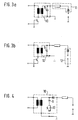
- FIGS. 3a and 3b show possibilities for the installation location of the high-voltage semiconductor switch
- FIG. 4 shows an ignition system with a capacitor that can be switched off on the secondary side.
- FIG. 1 shows the basic structure of an ignition system with an ignition coil 1, the primary winding 2 of which is connected via an ignition transistor 3 to a voltage supply U B , for example to the battery of a motor vehicle (not shown).
- the ignition transistor 3 is controlled in a known manner via a control terminal 4.
- the secondary winding 5 is connected on the one hand to ground potential and on the other hand via a breakover diode cascade 6, which acts as a high-voltage semiconductor switch, and an interference suppressor 7 to the spark plug 8.
- the ignition system shown in Figure 1 works as follows.
- FIG. 2 shows a structure similar to that of FIG. 1, but a double spark coil is used here.
- a trigger diode cascade 6 is assigned to each end of the ignition coil, the distinction being made here by corresponding indices a and b.
- These breakover diode cascade are assigned to the coil ends with different polarity.
- the capacitor 9 for amplifying the division effect is connected in parallel with the secondary winding 5 in front of the breakover diode cascades 6a and 6b. Similar to FIG. 1, the breakover diode cascades and the capacitor are arranged in the ignition coil housing 10 in this embodiment.
- FIGS. 3a and 3b show a structure similar to that in FIG. 1, the capacitor 9 being arranged in the ignition coil housing in both cases.
- the breakover diode cascade is arranged in the plug connector 11 in FIG. 3a and in the candle 12 in FIG. 3b. This has the advantage that the self-capacitance of the ignition line can also be used for the division effect.
- FIG. 4 also shows a structure similar to FIG. 1, but here a high-voltage switch 13 is arranged in series with the capacitor 9, parallel to the secondary winding 5.
- This high-voltage switch can be a light-triggerable high-voltage switch, for example.
- the capacitor 9 in the ignition coil housing and the high-voltage breakover diode, for example in the distributor rotor, the distributor middle plug, in the ignition line between the ignition coil and distributor, or directly in the ignition coil.
Landscapes
- Engineering & Computer Science (AREA)
- Chemical & Material Sciences (AREA)
- Combustion & Propulsion (AREA)
- Mechanical Engineering (AREA)
- General Engineering & Computer Science (AREA)
- Ignition Installations For Internal Combustion Engines (AREA)
Abstract
Claims (6)
- Installation d'allumage d'un moteur à combustion interne dont le secondaire de chaque bobine d'allumage (1) comporte au moins une cascade de diodes de basculement (6) comme commutateur de haute tension à semiconducteur, en amont de chaque bougie d'allumage (8), et qui pour une tension prédéterminée, passe brusquement de l'état bloqué à l'état conducteur pour créer les étincelles d'allumage, caractérisée en ce qu'entre la bobine d'allumage (1) et la cascade de diodes de basculement (6), en parallèle à l'enroulement de secondaire (5) de la bobine d'allumage (1), on a un condensateur (9) et le condensateur est logé dans le boîtier de la bobine d'allumage ou à proximité immédiate de la bobine d'allumage et le condensateur (9) est un condensateur en céramique à courbe de température, présentant une capacité plus faible à l'état chaud.
- Installation d'allumage selon la revendication 1, caractérisée en ce que pour des bobines à double étincelle, dans le boîtier de la bobine (10) à chaque extrémité de la bobine on a une cascade de diodes de basculement (6a, 6b) et le condensateur (9) est monté entre les deux cascades de diodes de basculement (6a, 6b).
- Installation d'allumage selon la revendication 2, caractérisée en ce que les cascades de diodes de basculement (6a, 6b) sont associées aux extrémités différentes de la bobine correspondant aux polarités différentes.
- Installation d'allumage selon l'une des revendications précédentes, caractérisée en ce que le condensateur (9) peut être branché ou coupé au choix.
- Installation d'allumage selon la revendication 4, caractérisée en ce que le commutateur est un commutateur de haute tension (13) commandé par la lumière, branché en série sur le condensateur (9).
- Installation d'allumage selon la revendication 4 ou 5, caractérisée en ce que le condensateur (9) est branché de préférence pour le démarrage à froid.
Applications Claiming Priority (3)
| Application Number | Priority Date | Filing Date | Title |
|---|---|---|---|
| DE4117808A DE4117808C2 (de) | 1991-05-31 | 1991-05-31 | Zündanlagen für Brennkraftmaschinen mit Hochspannungsschalter |
| DE4117808 | 1991-05-31 | ||
| PCT/DE1992/000305 WO1992021875A1 (fr) | 1991-05-31 | 1992-04-14 | Systemes d'allumage pour moteurs a combustion interne avec interrupteurs a haute tension |
Publications (2)
| Publication Number | Publication Date |
|---|---|
| EP0587576A1 EP0587576A1 (fr) | 1994-03-23 |
| EP0587576B1 true EP0587576B1 (fr) | 1996-01-24 |
Family
ID=6432844
Family Applications (1)
| Application Number | Title | Priority Date | Filing Date |
|---|---|---|---|
| EP92907664A Expired - Lifetime EP0587576B1 (fr) | 1991-05-31 | 1992-04-14 | Systemes d'allumage pour moteurs a combustion interne avec interrupteurs a haute tension |
Country Status (6)
| Country | Link |
|---|---|
| US (1) | US5379745A (fr) |
| EP (1) | EP0587576B1 (fr) |
| JP (1) | JPH06507461A (fr) |
| DE (2) | DE4117808C2 (fr) |
| ES (1) | ES2083165T3 (fr) |
| WO (1) | WO1992021875A1 (fr) |
Families Citing this family (8)
| Publication number | Priority date | Publication date | Assignee | Title |
|---|---|---|---|---|
| DE19502304A1 (de) * | 1995-01-26 | 1996-08-01 | Bosch Gmbh Robert | Zündanlage für Brennkraftmaschinen |
| DE19610862A1 (de) * | 1996-03-20 | 1997-09-25 | Bosch Gmbh Robert | Induktive Zündeinrichtung |
| DE19741963C1 (de) * | 1997-09-23 | 1999-03-11 | Siemens Ag | Vorrichtung zur Unterdrückung unerwünschter Zündungen bei einem Ottomotor |
| GB9722858D0 (en) * | 1997-10-29 | 1997-12-24 | Dibble Jonathan R | Ignition circuits |
| RU2293874C2 (ru) * | 2001-08-29 | 2007-02-20 | РЯЗАНСКИЙ ВОЕННЫЙ АВТОМОБИЛЬНЫЙ ИНСТИТУТ им. генерала армии В.П. Дубынина | Система зажигания карбюраторного двигателя внутреннего сгорания |
| FR2835886B1 (fr) * | 2002-02-08 | 2004-11-12 | Johnson Contr Automotive Elect | Module electronique pour bobine d'allumage de moteur a combustion interne |
| US6679235B1 (en) * | 2003-02-21 | 2004-01-20 | Delphi Technologies, Inc. | High power ignition system having high impedance to protect the transformer |
| EP1995452A1 (fr) * | 2007-05-21 | 2008-11-26 | Arora GmbH | Circuit d'ignition pour des moteur à combustion interne à allumage commandé |
Family Cites Families (21)
| Publication number | Priority date | Publication date | Assignee | Title |
|---|---|---|---|---|
| US2643284A (en) * | 1950-02-09 | 1953-06-23 | Eleanor H Putnam | Ignition system |
| US3200291A (en) * | 1961-01-23 | 1965-08-10 | Globe Union Inc | Ignition system |
| GB1106923A (en) * | 1965-03-10 | 1968-03-20 | Lucas Industries Ltd | Spark ignition systems |
| US3753428A (en) * | 1971-03-30 | 1973-08-21 | J Phillips | Ignition system |
| US4203403A (en) * | 1973-04-28 | 1980-05-20 | Nippondenso Co., Ltd. | Ignition device for an internal combustion engine |
| GB1473325A (en) * | 1973-06-29 | 1977-05-11 | Lucas Industries Ltd | Spark ignition systems for internal combustion engines |
| DE2606890C2 (de) * | 1976-02-20 | 1985-11-07 | Robert Bosch Gmbh, 7000 Stuttgart | Hochleistungszündanlage für Brennkraftmaschinen |
| JPS56124671A (en) * | 1980-03-07 | 1981-09-30 | Hitachi Ltd | Igniting apparatus |
| JPS6017949B2 (ja) * | 1980-04-24 | 1985-05-08 | サンケン電気株式会社 | 内燃機関の点火装置 |
| JPS61164073A (ja) * | 1985-01-14 | 1986-07-24 | Nissan Motor Co Ltd | 内燃機関用点火装置 |
| JPS61164074A (ja) * | 1985-01-16 | 1986-07-24 | Nissan Motor Co Ltd | 内燃機関用点火装置 |
| JPS61182469A (ja) * | 1985-02-08 | 1986-08-15 | Nissan Motor Co Ltd | 内燃機関の点火装置 |
| DE3513422C2 (de) * | 1985-04-15 | 1993-10-28 | Beru Werk Ruprecht Gmbh Co A | Zündanlage für Brennkraftmaschinen |
| JPS6270665A (ja) * | 1985-09-20 | 1987-04-01 | Yuu Shoji:Kk | 電気点火方式の内燃機関における二次回路用コンデンサ− |
| JPS62121863A (ja) * | 1985-11-21 | 1987-06-03 | Fuji Electric Co Ltd | 内燃機関用点火装置 |
| FR2606833B1 (fr) * | 1986-11-18 | 1989-02-24 | Peugeot | Dispositif d'allumage pour moteur a combustion |
| DE3888360D1 (de) * | 1987-09-18 | 1994-04-14 | Bosch Gmbh Robert | Hochspannungsschalter und verfahren zur ansteuerung von verbrauchern mittels des hochspannungsschalters. |
| DE3731393A1 (de) * | 1987-09-18 | 1989-04-06 | Bosch Gmbh Robert | Hochspannungsschalter |
| JPS6483853A (en) * | 1987-09-25 | 1989-03-29 | Hanshin Electrics | Ignition device for internal combustion engine |
| DE3935379A1 (de) * | 1989-10-24 | 1991-04-25 | Bosch Gmbh Robert | Hochspannungsschaltung mit hochspannungsschalter aus optoelektrischen halbleiterelementen |
| DE4020103A1 (de) * | 1990-06-23 | 1992-01-02 | Bosch Gmbh Robert | Hochspannungsschalter bei doppelfunkenspulen-zuendanllagen |
-
1991
- 1991-05-31 DE DE4117808A patent/DE4117808C2/de not_active Expired - Fee Related
-
1992
- 1992-04-14 EP EP92907664A patent/EP0587576B1/fr not_active Expired - Lifetime
- 1992-04-14 US US08/142,311 patent/US5379745A/en not_active Expired - Fee Related
- 1992-04-14 WO PCT/DE1992/000305 patent/WO1992021875A1/fr not_active Ceased
- 1992-04-14 DE DE59205186T patent/DE59205186D1/de not_active Expired - Fee Related
- 1992-04-14 ES ES92907664T patent/ES2083165T3/es not_active Expired - Lifetime
- 1992-04-14 JP JP4507624A patent/JPH06507461A/ja active Pending
Non-Patent Citations (1)
| Title |
|---|
| PATENT ABSTRACTS OF JAPAN vol. 13, no. 289 (M-845)(3637) 5. Juli 1989 & JP-A-1083853 * |
Also Published As
| Publication number | Publication date |
|---|---|
| EP0587576A1 (fr) | 1994-03-23 |
| DE4117808C2 (de) | 1994-09-22 |
| ES2083165T3 (es) | 1996-04-01 |
| JPH06507461A (ja) | 1994-08-25 |
| WO1992021875A1 (fr) | 1992-12-10 |
| DE4117808A1 (de) | 1992-12-03 |
| US5379745A (en) | 1995-01-10 |
| DE59205186D1 (de) | 1996-03-07 |
Similar Documents
| Publication | Publication Date | Title |
|---|---|---|
| DE3108635C2 (de) | Verteilerloses Zündsystem für Brennkraftmaschinen | |
| DE102013215663A1 (de) | Zündapparatur | |
| EP0587576B1 (fr) | Systemes d'allumage pour moteurs a combustion interne avec interrupteurs a haute tension | |
| WO2012130649A1 (fr) | Procédé et dispositif de prolongement de la durée de combustion d'une étincelle allumée par une bougie d'allumage dans un moteur à combustion interne | |
| DE2242325B2 (de) | Zuendanlage fuer brennkraftmaschinen mit einem magnetzuender | |
| DE2823391C2 (fr) | ||
| EP0070572A1 (fr) | Système d'allumage pour moteur à combustion interne | |
| DE2927058A1 (de) | Steuereinrichtung fuer eine zuendspule einer brennkraftmaschine | |
| EP0489264B1 (fr) | Système d'allumage électronique | |
| DE102013108658A1 (de) | Funkenstreckenanordnung | |
| DE2533046A1 (de) | Zuendeinrichtung fuer brennkraftmaschinen | |
| DE2126428A1 (de) | Transistorzundsystem | |
| EP0536157B1 (fr) | Interrupteur a haute tension pour des systemes d'allumage par bobines a deux sorties | |
| DE2237837A1 (de) | Zuendeinrichtung fuer einen verbrennungskraftmotor | |
| DE1539195C3 (de) | Elektronisches Zündsystem für gemischverdichtende Brennkraftmaschinen (Otto-Motoren), die vorzugsweise zum Antrieb von Kraftfahrzeugen dienen | |
| EP1280993B1 (fr) | Systeme d'allumage pour moteur a combustion interne | |
| EP1017940A2 (fr) | Dispositif de suppression d'allumages parasites dans un moteur a essence | |
| EP0591686A2 (fr) | Elément de connexion pour dispositif d'allumage | |
| DE4133253A1 (de) | Zuendanlage fuer brennkraftmaschinen | |
| DE2917617C2 (de) | Zündeinrichtung für Brennkraftmaschinen, Öl- und Gasbrenner u. dgl. | |
| DE3037113C2 (de) | Zündschaltung für einen Fremdzündungs-Verbrennungsmotor | |
| EP0425953B1 (fr) | Installation d'allumage sans contact pour moteurs à combustion | |
| EP0968368A1 (fr) | Montage pour etage final d'allumage | |
| DE2203938C3 (de) | Induktive Speicher-Zündvorrichtung | |
| DE2430389C2 (de) | Vorrichtung zur Erhöhung der Zündspannung in Zündeinrichtungen für Brennkraftmaschinen |
Legal Events
| Date | Code | Title | Description |
|---|---|---|---|
| PUAI | Public reference made under article 153(3) epc to a published international application that has entered the european phase |
Free format text: ORIGINAL CODE: 0009012 |
|
| 17P | Request for examination filed |
Effective date: 19931029 |
|
| AK | Designated contracting states |
Kind code of ref document: A1 Designated state(s): DE ES FR GB IT SE |
|
| 17Q | First examination report despatched |
Effective date: 19950220 |
|
| GRAA | (expected) grant |
Free format text: ORIGINAL CODE: 0009210 |
|
| AK | Designated contracting states |
Kind code of ref document: B1 Designated state(s): DE ES FR GB IT SE |
|
| ET | Fr: translation filed | ||
| REF | Corresponds to: |
Ref document number: 59205186 Country of ref document: DE Date of ref document: 19960307 |
|
| REG | Reference to a national code |
Ref country code: ES Ref legal event code: FG2A Ref document number: 2083165 Country of ref document: ES Kind code of ref document: T3 |
|
| ITF | It: translation for a ep patent filed | ||
| GBT | Gb: translation of ep patent filed (gb section 77(6)(a)/1977) |
Effective date: 19960411 |
|
| PLBE | No opposition filed within time limit |
Free format text: ORIGINAL CODE: 0009261 |
|
| 26N | No opposition filed | ||
| PGFP | Annual fee paid to national office [announced via postgrant information from national office to epo] |
Ref country code: GB Payment date: 19980327 Year of fee payment: 7 |
|
| PGFP | Annual fee paid to national office [announced via postgrant information from national office to epo] |
Ref country code: FR Payment date: 19980420 Year of fee payment: 7 |
|
| PGFP | Annual fee paid to national office [announced via postgrant information from national office to epo] |
Ref country code: SE Payment date: 19980423 Year of fee payment: 7 |
|
| PGFP | Annual fee paid to national office [announced via postgrant information from national office to epo] |
Ref country code: ES Payment date: 19980430 Year of fee payment: 7 |
|
| PGFP | Annual fee paid to national office [announced via postgrant information from national office to epo] |
Ref country code: DE Payment date: 19980619 Year of fee payment: 7 |
|
| PG25 | Lapsed in a contracting state [announced via postgrant information from national office to epo] |
Ref country code: GB Free format text: LAPSE BECAUSE OF NON-PAYMENT OF DUE FEES Effective date: 19990414 |
|
| PG25 | Lapsed in a contracting state [announced via postgrant information from national office to epo] |
Ref country code: SE Free format text: LAPSE BECAUSE OF NON-PAYMENT OF DUE FEES Effective date: 19990415 Ref country code: ES Free format text: LAPSE BECAUSE OF EXPIRATION OF PROTECTION Effective date: 19990415 |
|
| GBPC | Gb: european patent ceased through non-payment of renewal fee |
Effective date: 19990414 |
|
| PG25 | Lapsed in a contracting state [announced via postgrant information from national office to epo] |
Ref country code: FR Free format text: LAPSE BECAUSE OF NON-PAYMENT OF DUE FEES Effective date: 19991231 |
|
| EUG | Se: european patent has lapsed |
Ref document number: 92907664.4 |
|
| REG | Reference to a national code |
Ref country code: FR Ref legal event code: ST |
|
| PG25 | Lapsed in a contracting state [announced via postgrant information from national office to epo] |
Ref country code: DE Free format text: LAPSE BECAUSE OF NON-PAYMENT OF DUE FEES Effective date: 20000201 |
|
| REG | Reference to a national code |
Ref country code: ES Ref legal event code: FD2A Effective date: 20010601 |
|
| PG25 | Lapsed in a contracting state [announced via postgrant information from national office to epo] |
Ref country code: IT Free format text: LAPSE BECAUSE OF NON-PAYMENT OF DUE FEES;WARNING: LAPSES OF ITALIAN PATENTS WITH EFFECTIVE DATE BEFORE 2007 MAY HAVE OCCURRED AT ANY TIME BEFORE 2007. THE CORRECT EFFECTIVE DATE MAY BE DIFFERENT FROM THE ONE RECORDED. Effective date: 20050414 |