EP0587671B1 - Syteme de lentilles servant de condenseur optique pour retroprojecteur - Google Patents
Syteme de lentilles servant de condenseur optique pour retroprojecteur Download PDFInfo
- Publication number
- EP0587671B1 EP0587671B1 EP92911592A EP92911592A EP0587671B1 EP 0587671 B1 EP0587671 B1 EP 0587671B1 EP 92911592 A EP92911592 A EP 92911592A EP 92911592 A EP92911592 A EP 92911592A EP 0587671 B1 EP0587671 B1 EP 0587671B1
- Authority
- EP
- European Patent Office
- Prior art keywords
- lens
- lens system
- plano
- fresnel
- light source
- Prior art date
- Legal status (The legal status is an assumption and is not a legal conclusion. Google has not performed a legal analysis and makes no representation as to the accuracy of the status listed.)
- Expired - Lifetime
Links
- 238000005286 illumination Methods 0.000 claims abstract description 23
- 239000011521 glass Substances 0.000 claims abstract description 22
- 230000005499 meniscus Effects 0.000 claims abstract description 20
- 230000004075 alteration Effects 0.000 claims description 8
- 230000003287 optical effect Effects 0.000 claims description 8
- 210000001747 pupil Anatomy 0.000 abstract description 4
- 238000000926 separation method Methods 0.000 description 4
- 230000009977 dual effect Effects 0.000 description 2
- 230000000694 effects Effects 0.000 description 2
- 239000004973 liquid crystal related substance Substances 0.000 description 2
- 230000005855 radiation Effects 0.000 description 2
- RZVAJINKPMORJF-UHFFFAOYSA-N Acetaminophen Chemical compound CC(=O)NC1=CC=C(O)C=C1 RZVAJINKPMORJF-UHFFFAOYSA-N 0.000 description 1
- 229920002972 Acrylic fiber Polymers 0.000 description 1
- 238000003491 array Methods 0.000 description 1
- 239000005388 borosilicate glass Substances 0.000 description 1
- 239000005331 crown glasses (windows) Substances 0.000 description 1
- 230000007423 decrease Effects 0.000 description 1
- 230000003247 decreasing effect Effects 0.000 description 1
- 230000001627 detrimental effect Effects 0.000 description 1
- 238000010438 heat treatment Methods 0.000 description 1
- 238000004519 manufacturing process Methods 0.000 description 1
- 239000000463 material Substances 0.000 description 1
- 229910001507 metal halide Inorganic materials 0.000 description 1
- 150000005309 metal halides Chemical class 0.000 description 1
- 238000000034 method Methods 0.000 description 1
- 239000005297 pyrex Substances 0.000 description 1
- 239000007787 solid Substances 0.000 description 1
Images

Classifications
-
- G—PHYSICS
- G03—PHOTOGRAPHY; CINEMATOGRAPHY; ANALOGOUS TECHNIQUES USING WAVES OTHER THAN OPTICAL WAVES; ELECTROGRAPHY; HOLOGRAPHY
- G03B—APPARATUS OR ARRANGEMENTS FOR TAKING PHOTOGRAPHS OR FOR PROJECTING OR VIEWING THEM; APPARATUS OR ARRANGEMENTS EMPLOYING ANALOGOUS TECHNIQUES USING WAVES OTHER THAN OPTICAL WAVES; ACCESSORIES THEREFOR
- G03B21/00—Projectors or projection-type viewers; Accessories therefor
- G03B21/132—Overhead projectors, i.e. capable of projecting hand-writing or drawing during action
-
- G—PHYSICS
- G02—OPTICS
- G02B—OPTICAL ELEMENTS, SYSTEMS OR APPARATUS
- G02B19/00—Condensers, e.g. light collectors or similar non-imaging optics
- G02B19/0004—Condensers, e.g. light collectors or similar non-imaging optics characterised by the optical means employed
- G02B19/0028—Condensers, e.g. light collectors or similar non-imaging optics characterised by the optical means employed refractive and reflective surfaces, e.g. non-imaging catadioptric systems
-
- G—PHYSICS
- G02—OPTICS
- G02B—OPTICAL ELEMENTS, SYSTEMS OR APPARATUS
- G02B19/00—Condensers, e.g. light collectors or similar non-imaging optics
- G02B19/0033—Condensers, e.g. light collectors or similar non-imaging optics characterised by the use
- G02B19/0047—Condensers, e.g. light collectors or similar non-imaging optics characterised by the use for use with a light source
-
- Y—GENERAL TAGGING OF NEW TECHNOLOGICAL DEVELOPMENTS; GENERAL TAGGING OF CROSS-SECTIONAL TECHNOLOGIES SPANNING OVER SEVERAL SECTIONS OF THE IPC; TECHNICAL SUBJECTS COVERED BY FORMER USPC CROSS-REFERENCE ART COLLECTIONS [XRACs] AND DIGESTS
- Y10—TECHNICAL SUBJECTS COVERED BY FORMER USPC
- Y10S—TECHNICAL SUBJECTS COVERED BY FORMER USPC CROSS-REFERENCE ART COLLECTIONS [XRACs] AND DIGESTS
- Y10S353/00—Optics: image projectors
- Y10S353/03—Transparent
Definitions
- This invention relates to overhead projectors, and in particular, those of the transmissive type.
- This uniformity is especially important for the use of LCD (liquid crystal display) projection panels, which are placed on the stage of overhead projectors.
- LCD liquid crystal display
- the nonuniformity of illumination at the stage produced by many high intensity overhead projectors causes uneven heating of the liquid crystal material across the stage plane. This, in turn, causes uneven contrast in the projected image.
- the above objects are accomplished by providing a multi-element wide-angle light condensing system for use in an overhead projector.
- the lens system of the invention is defined in claim 1.
- the system provides highly uniform illumination at the stage of the overhead projector, by combining dual spherical glass condenser lenses with dual element plastic aspheric Fresnel lenses. High collection efficiency achieved by the system provides high light levels at the projected image.
- the uniform illumination makes the system especially useful for LCD projection panels used in conjunction with overhead projectors.
- FIG. 1 illustrates a typical overhead projector 10 which could advantageously use the lens system of the present invention.
- the projector 10 includes a stage 12 upon which a transparency or other object to be imaged may be placed, a projection lens 14 supported above the stage 12 and a plane mirror 16 for directing an image of the transparency onto a distant, substantially vertical surface.
- Light necessary to produce the image is provided by a light source and lens system located within the body of the projector under the stage.
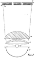
- FIG. 2 shows the illumination system of the current invention.
- the illustration of Figure 2 is not to scale, particularly in that the Fresnel lenses and stage appearing in the upper portion of Figure 2 have a largest dimension approximately four times that of the condensing lenses appearing in the lower portion of the drawing.
- This illumination system consists of a light source 18, a mirror 20, a glass positive meniscus lens 22 closely spaced to a glass positive plano-convex lens 24 and a Fresnel lens system 26, 28. It is preferred that the two Fresnel lenses 26 and 28 be a doublet for manufacturing efficiency and economy, but the Fresnel lenses 26 and 28 need not be a doublet.
- the light source 18 is preferably an isotropic plasma discharge lamp, but may be an incandescent Lambertian source.
- the curved surfaces of the glass lenses 22, 24 are spherical, and the profile of the grooved surfaces of the Fresnel lenses 26, 28 are aspherical. These lenses 22-28 form an image of the light source 18 at the entrance pupil of the projection lens 14.
- the glass condensers 22, 24 of the current invention produce a nearly constant or decreasing angular separation of the exiting light rays. This distribution provides a more uniform illumination at the overhead projector stage 12, giving a more uniform projected image. This illumination distribution is achieved by introducing considerable spherical aberration in the divergent light rays exiting the glass condenser lenses 22, 24.
- the aspherical profile of the Fresnel lenses 26, 28 then corrects the spherical aberration of the glass lenses 22, 24, such that a good image of the light source 18 will be formed at the entrance pupil of the projection lens 14.
- the power and aperture of the plano-convex lens 24 are chosen such that rays from the outer edge of this lens 24 intersect only at locations on the Fresnel lens 26 which are well removed from its center. Secondly, this intersection point is controlled to be just outside the corner of the stage 12 diagonal, which acts as a stop. All remaining rays which fall within the stage area can then be brought to a common focus by the aspheric Fresnel lenses 26 and 28.
- a meniscus lens can be used in combination with a plano-convex lens as a converging condenser, if the total power is divided nearly equally between the two.
- the radius of the concave surface of the meniscus lens 22 is chosen such that the lens 22 can be positioned as close to the light source 18 as possible, still allowing the light source 18 to be removed for replacement.
- this lens 22 is often manufactured from a heat-resistant low-expansion borosilicate glass, such as PYREX.
- the plano-convex lens 24 is an optical crown glass, such as type B270.
- the Fresnel lenses 26, 28 are manufactured from even less heat-resistant acrylic plastic.
- the system of the current invention can be utilized for overhead projection when the following system requirements are satisfied. 1.91 f 12 ⁇ f 1 ⁇ 23.5 f 12 1.06 f 12 ⁇ f 2 ⁇ 2.09 f 12 0.44 f 12 ⁇ f 3 ⁇ 2.64 f 12 0.82 f 12 ⁇ d 23 ⁇ 5.49 f 12 where:
- the heat-resistant borosilicate meniscus lens 22 has a focal length of 350 mm, a diameter of 92 mm, a radius of curvature of the surface closer to the light source 18 of 151.69 mm and a radius of curvature of the surface farther from the light source of 80.93 mm.
- the optical crown plano-convex lens 24 has a focal length of 135 mm, a diameter of 113 mm and a radius of curvature of the surface farther from the light source of 70.59 mm.
- the Fresnel lens system 26, 28 has a combined focal length of 182.5 mm and the overhead projector 10 has a 10.5" (side-to-side) stage 12.
- the projection lens 14 is a 317 mm Cooke type triplet. With a 575 watt plasma discharge lamp 18 of the metal halide type operating at 95 volts, it is possible to obtain 6000 screen lumens with an overall projected light uniformity (edge-to-center ratio) exceeding 75%.
Landscapes
- Physics & Mathematics (AREA)
- General Physics & Mathematics (AREA)
- Optics & Photonics (AREA)
- Lenses (AREA)
- Overhead Projectors And Projection Screens (AREA)
- Projection Apparatus (AREA)
Abstract
Claims (11)
- Système de lentilles utilisable dans un rétroprojecteur (10) comportant un plateau (12) pour supporter un objet dont on veut projeter l'image, une source de lumière (18) disposée le long d'un axe optique perpendiculaire à un plan défini par le plateau (12), une lentille de projection (14) disposée le long de l'axe optique de l'autre côté du plateau par rapport à la source de lumière, et un réflecteur total (20) placé sur le dit axe optique pour réfléchir la lumière venant de la dite source de lumière vers le dit plateau (12), le système de lentilles comprenant :une lentille à ménisque sphérique (22) ayant une puissance optique positive ;un système de lentilles de Fresnel asphériques (26, 28), ayant une puissance optique positive et disposé sur l'axe optique de la dite lentille à ménisque (22) ; le système de lentilles étant caractérisé par :une lentille plan-convexe sphérique (24) placée entre la dite lentille à ménisque (22) et le dit système de lentilles de Fresnel (26, 28), le côté concave de la dite lentille à ménisque (22) et le côté plan de la dite lentille plan-convexe (24) étant tous deux tournés à l'opposé du dit système de lentilles de Fresnel (26, 28) ;l'agencement étant tel que, lorsqu'il est placé dans le dit rétroprojecteur avec le côté concave de la dite lentille à ménisque en regard de la source de lumière (18) et le système de lentilles de Fresnel en regard du plateau (12), la dite lentille à ménisque (22) et la dite lentille plan-convexe (24) agissent en combinaison pour introduire une aberration sphérique dans les rayons lumineux divergents qui sortent de la dite lentille plan-convexe (24), et le dit système de lentilles de Fresnel asphériques corrige la dite aberration sphérique par convergence des rayons lumineux à un foyer commun à l'endroit de la lentille de projection (14), ce qui produit un éclairage convergent très intense et uniforme à l'endroit du plateau (12).
- Système de lentilles suivant la revendication 1, dans lequel les conditions suivantes sont satisfaites pour le dit système de lentilles :


 f1 = longueur focale de la dite lentille à ménisque (22)f2 = longueur focale de la dite lentille plan-convexe (24)f3 = longueur focale du dit système de lentilles de Fresnel asphériques (26, 28)d23 = distance entre la dite lentille plan-convexe et le dit système de lentilles de Fresnelf12 = longueur focale combinée de la dite lentille à ménisque et de la dite lentille plan-convexe.
 - Système de lentilles suivant la revendication 1, dans lequel la dite lentille à ménisque (22) est une lentille en verre résistant à la chaleur ayant une longueur focale de 350 mm.
- Système de lentilles suivant la revendication 3, dans lequel la dite lentille à ménisque (22) a un diamètre de 92 mm.
- Système de lentilles suivant la revendication 4, dans lequel la dite lentille à ménisque (22) a un rayon de courbure de la surface la plus proche de la dite source de lumière (18) de 151,69 mm et un rayon de courbure de la surface la plus éloignée de la dite source de lumière de 80,93 mm.
- Système de lentilles suivant la revendication 1, dans lequel la dite lentille plan-convexe (24) est une lentille en verre ayant une longueur focale de 135 mm.
- Système de lentilles suivant la revendication 6, dans lequel la dite lentille plan-convexe (24) a un diamètre de 113 mm.
- Système de lentilles suivant la revendication 7, dans lequel la dite lentille plan-convexe (24) a un rayon de courbure de la surface la plus éloignée de la dite source de lumière (18) de 70,59 mm.
- Système de lentilles suivant la revendication 1, dans lequel le dit système de lentilles de Fresnel est un doublet de lentilles de Fresnel (26, 28).
- Système de lentilles suivant la revendication 1, dans lequel le dit système de lentilles de Fresnel (26, 28) a une longueur focale combinée de 182,5 mm.
- Système de lentilles suivant la revendication 10, dans lequel le dit système de lentilles de Fresnel est un doublet de lentilles de Fresnel (26, 28).
Applications Claiming Priority (3)
| Application Number | Priority Date | Filing Date | Title |
|---|---|---|---|
| US07/711,803 US5092672A (en) | 1991-06-07 | 1991-06-07 | Condenser lens system for overhead projector |
| US711803 | 1991-06-07 | ||
| PCT/US1992/003491 WO1992022008A1 (fr) | 1991-06-07 | 1992-04-28 | Syteme de lentilles servant de condenseur optique pour retroprojecteur |
Publications (2)
| Publication Number | Publication Date |
|---|---|
| EP0587671A1 EP0587671A1 (fr) | 1994-03-23 |
| EP0587671B1 true EP0587671B1 (fr) | 1997-09-10 |
Family
ID=24859589
Family Applications (1)
| Application Number | Title | Priority Date | Filing Date |
|---|---|---|---|
| EP92911592A Expired - Lifetime EP0587671B1 (fr) | 1991-06-07 | 1992-04-28 | Syteme de lentilles servant de condenseur optique pour retroprojecteur |
Country Status (8)
| Country | Link |
|---|---|
| US (1) | US5092672A (fr) |
| EP (1) | EP0587671B1 (fr) |
| JP (1) | JPH06508446A (fr) |
| KR (1) | KR100205702B1 (fr) |
| BR (1) | BR9206097A (fr) |
| CA (1) | CA2108007A1 (fr) |
| DE (1) | DE69222163T2 (fr) |
| WO (1) | WO1992022008A1 (fr) |
Families Citing this family (14)
| Publication number | Priority date | Publication date | Assignee | Title |
|---|---|---|---|---|
| US5092672A (en) * | 1991-06-07 | 1992-03-03 | Minnesota Mining And Manufacturing Company | Condenser lens system for overhead projector |
| US5517278A (en) * | 1991-06-12 | 1996-05-14 | Matsushita Electric Industrial Co., Ltd. | Viewfinder for video cameras |
| US5331360A (en) * | 1993-03-22 | 1994-07-19 | Eastman Kodak Company | Adaptor for overhead projector |
| US5400094A (en) * | 1993-03-31 | 1995-03-21 | Minnesota Mining And Manufacturing Company | Condensers for overhead projectors |
| US5515123A (en) * | 1994-02-17 | 1996-05-07 | Minnesota Mining And Manufacturing Company | Condensers for illumination systems |
| US5823662A (en) * | 1994-08-25 | 1998-10-20 | Lightware, Inc. | High efficiency illumination system |
| USD396871S (en) | 1996-09-03 | 1998-08-11 | Acco-Rexel Group Services Plc. | Overhead projector |
| EP0864897A3 (fr) * | 1997-02-27 | 1998-10-28 | Canon Kabushiki Kaisha | Dispositif de source de lumière, système d'éclairage et projecteur d'images |
| US20030087447A1 (en) | 2001-11-08 | 2003-05-08 | Blouin Matthew R | Sample well strip |
| FR2835063A1 (fr) * | 2002-01-21 | 2003-07-25 | Alm | Condenseur optique, dispositif d'eclairage l'incorporant et procede de fabrication |
| USD481133S1 (en) | 2002-04-18 | 2003-10-21 | Instrumentation Laboratory Company | Sample well-strip for an automated sample analyzer |
| US20050017619A1 (en) * | 2003-07-21 | 2005-01-27 | Sheng-Chih Wan | Modified high-brightness flat lamp structure |
| US7731899B2 (en) | 2007-02-08 | 2010-06-08 | Biokit, S.A. | Apparatus and methods for dispensing sample holders |
| TW201319629A (zh) * | 2011-11-08 | 2013-05-16 | Probright Technology Inc | 太陽能線性菲涅爾聚光透鏡 |
Citations (1)
| Publication number | Priority date | Publication date | Assignee | Title |
|---|---|---|---|---|
| DE2831926A1 (de) * | 1978-07-20 | 1980-02-07 | Hellmut Niethammmer Fa | Kondensorsystem fuer einen grossbuehnen- projektionsapparat |
Family Cites Families (15)
| Publication number | Priority date | Publication date | Assignee | Title |
|---|---|---|---|---|
| US2186123A (en) * | 1937-01-27 | 1940-01-09 | Zeiss Ikon Ag | Illuminating system |
| US2637242A (en) * | 1949-02-08 | 1953-05-05 | American Optical Corp | Condenser lens system for projectors |
| US3051043A (en) * | 1959-08-31 | 1962-08-28 | Garry V Miller | Projection system |
| US3241440A (en) * | 1963-12-26 | 1966-03-22 | Bausch & Lomb | Illumination system |
| US3302517A (en) * | 1964-09-25 | 1967-02-07 | Joseph F Henkel | Xenon optics system |
| US3296923A (en) * | 1965-01-04 | 1967-01-10 | Gen Electric | Lenticulated collimating condensing system |
| DE1472288B2 (de) * | 1966-07-06 | 1972-04-20 | Ernst Leitz Gmbh, 6330 Wetzlar | Schreibprojektor |
| US3505771A (en) * | 1968-02-12 | 1970-04-14 | Walter W Thompson | Acoustical ceiling |
| JPS5243095B2 (fr) * | 1973-08-03 | 1977-10-28 | ||
| JPS5262434A (en) * | 1975-11-18 | 1977-05-23 | Fuji Photo Film Co Ltd | Image distortion correction device for projector |
| US4436393A (en) * | 1983-01-03 | 1984-03-13 | Minnesota Mining And Manufacturing Company | Distortion correction for an overhead projector system |
| US4436392A (en) * | 1983-01-03 | 1984-03-13 | Minnesota Mining And Manufacturing Company | Distortion correction for an overhead projector system |
| US4561740A (en) * | 1984-06-06 | 1985-12-31 | Minnesota Mining And Manufacturing Company | Dual-magnification rear projection lectern |
| US4741613A (en) * | 1986-12-19 | 1988-05-03 | Minnesota Mining And Manufacturing Company | Reduced height transmissive overhead projector |
| US5092672A (en) * | 1991-06-07 | 1992-03-03 | Minnesota Mining And Manufacturing Company | Condenser lens system for overhead projector |
-
1991
- 1991-06-07 US US07/711,803 patent/US5092672A/en not_active Expired - Fee Related
-
1992
- 1992-04-28 EP EP92911592A patent/EP0587671B1/fr not_active Expired - Lifetime
- 1992-04-28 BR BR9206097A patent/BR9206097A/pt not_active IP Right Cessation
- 1992-04-28 WO PCT/US1992/003491 patent/WO1992022008A1/fr not_active Ceased
- 1992-04-28 DE DE69222163T patent/DE69222163T2/de not_active Expired - Fee Related
- 1992-04-28 CA CA002108007A patent/CA2108007A1/fr not_active Abandoned
- 1992-04-28 KR KR1019930703480A patent/KR100205702B1/ko not_active Expired - Fee Related
- 1992-04-28 JP JP4511446A patent/JPH06508446A/ja active Pending
Patent Citations (1)
| Publication number | Priority date | Publication date | Assignee | Title |
|---|---|---|---|---|
| DE2831926A1 (de) * | 1978-07-20 | 1980-02-07 | Hellmut Niethammmer Fa | Kondensorsystem fuer einen grossbuehnen- projektionsapparat |
Non-Patent Citations (1)
| Title |
|---|
| H.Naumann, G. Schröder, "Bauelemente der Optik", 4. ed., Carl Hansen Verlag, München 1983, p.304-309. * |
Also Published As
| Publication number | Publication date |
|---|---|
| KR100205702B1 (ko) | 1999-07-01 |
| BR9206097A (pt) | 1994-08-02 |
| US5092672A (en) | 1992-03-03 |
| JPH06508446A (ja) | 1994-09-22 |
| WO1992022008A1 (fr) | 1992-12-10 |
| DE69222163T2 (de) | 1998-03-12 |
| DE69222163D1 (de) | 1997-10-16 |
| CA2108007A1 (fr) | 1992-12-08 |
| EP0587671A1 (fr) | 1994-03-23 |
Similar Documents
| Publication | Publication Date | Title |
|---|---|---|
| US4498742A (en) | Illumination optical arrangement | |
| US5015088A (en) | Illuminating apparatus for projection purposes | |
| US5871266A (en) | Projection-type display device | |
| US5092672A (en) | Condenser lens system for overhead projector | |
| US4571041A (en) | Three dimensional projection arrangement | |
| US5504544A (en) | Projector with multiple lamp light source | |
| JPH043528B2 (fr) | ||
| JP2002521704A (ja) | 光源から射出する光を表面に配向する装置 | |
| EP0115900B1 (fr) | Correction de distorsion dans un rétroprojecteur | |
| US4741613A (en) | Reduced height transmissive overhead projector | |
| US6024452A (en) | Prismatic light beam homogenizer for projection displays | |
| US3253505A (en) | Projection of images onto inclined screens | |
| US4492442A (en) | Three dimensional projection arrangement | |
| EP0231029A2 (fr) | Système optique | |
| EP0059193B1 (fr) | Systeme optique de projection | |
| US4457600A (en) | Light projection systems | |
| JP2906543B2 (ja) | マイクロリーダプリンタの照明系 | |
| JPH08271831A (ja) | 光幅調節装置及びこれを採用した画像投射機 | |
| JPH11167064A (ja) | 照明装置 | |
| US5515123A (en) | Condensers for illumination systems | |
| JPH0125046B2 (fr) | ||
| US4988176A (en) | Projection lens | |
| EP0864909A1 (fr) | Dispositif d'éclairage | |
| KR100248011B1 (ko) | 프로젝터용투사렌즈유니트 | |
| RU2344452C2 (ru) | Проекционная оптическая система |
Legal Events
| Date | Code | Title | Description |
|---|---|---|---|
| PUAI | Public reference made under article 153(3) epc to a published international application that has entered the european phase |
Free format text: ORIGINAL CODE: 0009012 |
|
| 17P | Request for examination filed |
Effective date: 19940103 |
|
| AK | Designated contracting states |
Kind code of ref document: A1 Designated state(s): DE FR GB IT SE |
|
| 17Q | First examination report despatched |
Effective date: 19950904 |
|
| GRAG | Despatch of communication of intention to grant |
Free format text: ORIGINAL CODE: EPIDOS AGRA |
|
| GRAH | Despatch of communication of intention to grant a patent |
Free format text: ORIGINAL CODE: EPIDOS IGRA |
|
| GRAH | Despatch of communication of intention to grant a patent |
Free format text: ORIGINAL CODE: EPIDOS IGRA |
|
| GRAA | (expected) grant |
Free format text: ORIGINAL CODE: 0009210 |
|
| AK | Designated contracting states |
Kind code of ref document: B1 Designated state(s): DE FR GB IT SE |
|
| ITF | It: translation for a ep patent filed | ||
| REF | Corresponds to: |
Ref document number: 69222163 Country of ref document: DE Date of ref document: 19971016 |
|
| ET | Fr: translation filed | ||
| PLBE | No opposition filed within time limit |
Free format text: ORIGINAL CODE: 0009261 |
|
| STAA | Information on the status of an ep patent application or granted ep patent |
Free format text: STATUS: NO OPPOSITION FILED WITHIN TIME LIMIT |
|
| 26N | No opposition filed | ||
| REG | Reference to a national code |
Ref country code: GB Ref legal event code: IF02 |
|
| PGFP | Annual fee paid to national office [announced via postgrant information from national office to epo] |
Ref country code: FR Payment date: 20030418 Year of fee payment: 12 |
|
| PGFP | Annual fee paid to national office [announced via postgrant information from national office to epo] |
Ref country code: SE Payment date: 20030422 Year of fee payment: 12 |
|
| PGFP | Annual fee paid to national office [announced via postgrant information from national office to epo] |
Ref country code: GB Payment date: 20030423 Year of fee payment: 12 |
|
| PGFP | Annual fee paid to national office [announced via postgrant information from national office to epo] |
Ref country code: DE Payment date: 20030430 Year of fee payment: 12 |
|
| PG25 | Lapsed in a contracting state [announced via postgrant information from national office to epo] |
Ref country code: GB Free format text: LAPSE BECAUSE OF NON-PAYMENT OF DUE FEES Effective date: 20040428 |
|
| PG25 | Lapsed in a contracting state [announced via postgrant information from national office to epo] |
Ref country code: SE Free format text: LAPSE BECAUSE OF NON-PAYMENT OF DUE FEES Effective date: 20040429 |
|
| PG25 | Lapsed in a contracting state [announced via postgrant information from national office to epo] |
Ref country code: DE Free format text: LAPSE BECAUSE OF NON-PAYMENT OF DUE FEES Effective date: 20041103 |
|
| EUG | Se: european patent has lapsed | ||
| GBPC | Gb: european patent ceased through non-payment of renewal fee |
Effective date: 20040428 |
|
| PG25 | Lapsed in a contracting state [announced via postgrant information from national office to epo] |
Ref country code: FR Free format text: LAPSE BECAUSE OF NON-PAYMENT OF DUE FEES Effective date: 20041231 |
|
| REG | Reference to a national code |
Ref country code: FR Ref legal event code: ST |
|
| PG25 | Lapsed in a contracting state [announced via postgrant information from national office to epo] |
Ref country code: IT Free format text: LAPSE BECAUSE OF NON-PAYMENT OF DUE FEES Effective date: 20050428 |