EP0588588A2 - Dispositif électromagnétique - Google Patents
Dispositif électromagnétique Download PDFInfo
- Publication number
- EP0588588A2 EP0588588A2 EP93307208A EP93307208A EP0588588A2 EP 0588588 A2 EP0588588 A2 EP 0588588A2 EP 93307208 A EP93307208 A EP 93307208A EP 93307208 A EP93307208 A EP 93307208A EP 0588588 A2 EP0588588 A2 EP 0588588A2
- Authority
- EP
- European Patent Office
- Prior art keywords
- core
- pole piece
- circuit breaker
- cavity
- coil
- Prior art date
- Legal status (The legal status is an assumption and is not a legal conclusion. Google has not performed a legal analysis and makes no representation as to the accuracy of the status listed.)
- Granted
Links
Images


Classifications
-
- H—ELECTRICITY
- H01—ELECTRIC ELEMENTS
- H01H—ELECTRIC SWITCHES; RELAYS; SELECTORS; EMERGENCY PROTECTIVE DEVICES
- H01H71/00—Details of the protective switches or relays covered by groups H01H73/00 - H01H83/00
- H01H71/10—Operating or release mechanisms
- H01H71/12—Automatic release mechanisms with or without manual release
- H01H71/24—Electromagnetic mechanisms
- H01H71/34—Electromagnetic mechanisms having two or more armatures controlled by a common winding
- H01H71/345—Electromagnetic mechanisms having two or more armatures controlled by a common winding having a delayed movable core and a movable armature
Definitions
- THIS INVENTION relates to an electro-magnetically operable device for a circuit breaker.
- an electro-magnetically operable device for a circuit breaker including a coil which defines a cavity; a first core arranged in the cavity, the first core being displaceable within the cavity in a damped manner between a first, normal position and a second position; a first urging means for urging the first core from its second position towards its first position; a second core arranged in the cavity, adjacent the first core, the second core being displaceable within the cavity between a first, normal position and a second position; a second urging means for urging the second core from its second position towards its first position; and a magnetic path defining means arranged about at least a part of the coil, the magnetic path defining means including a pole piece, the pole piece and the cores being arranged such that a gap between the first core, when in its normal position, and the pole piece is less than a gap between the second core, when in its normal position, and the pole piece, with the second position of each core being closer to the pole piece than the first
- the first core may be housed in a sealed canister which contains a liquid to damp movement of the first core.
- the first and second urging means may be helical springs which are under compression, each spring being arranged intermediate its associated core and the pole piece.
- the coil may have a round or oval shape.
- the magnetic path defining means may include a stator frame arranged about the coil and an armature pivotally arranged relative to the stator frame, the armature being connectable to a tripping mechanism of the circuit breaker.
- An air gap may be defined between the stator frame and the pole piece.
- the second core may then be located on that side of the cavity on which the air gap between the pole piece and the stator frame is located.
- the stator frame may thus define two openings, one for the first-core and one for the second core, the cores projecting through said openings.
- the cores may move towards the pole piece when moving from their first positions to their second positions and may abut against the pole piece when in their second positions.
- An end of the second core may carry a link for mechanically linking the second core to a moving contact carrier of the circuit breaker, the link being a lost-motion link such that the moving contact carrier can move independently of the second core and the second core can, to a predetermined extent, move independently of the moving contact carrier.
- the moving contact carrier is displaceable between an "on" position in which the electrical path of the circuit breaker is closed and an "off" position in which the electrical path is open.
- the lost-motion link is then such that the second core may move from its first position towards its second position without moving the moving contact carrier when the moving contact carrier is in its "on” position; and the moving contact carrier may move from its "on” position towards its “off” position without displacing the second core, when the second core is in its first position.
- the reluctance of a magnetic circuit formed by the armature, portions of the stator frame and the pole piece and the first core is significantly decreased, thereby increasing the electro-magnetic force acting on the pivoted armature which is large enough to displace the armature into contact with the stator frame and the pole piece and thereby trip the circuit breaker.
- the force on the first core is larger than that on the second core, but the closing speed of the first core is considerably slower than that of the second core due to the effect of the liquid.
- the force on the second core is sufficiently large to compress the spring associated with the second core and the second core is displaced into contact with the pole piece in a relatively instantaneous manner. Due to the relatively high current, the armature is attracted to the pole piece, thereby tripping the breaker even before the gap of the second core is completely closed. When the armature closes, the reluctance of the magnetic circuit passing through the second core is reduced causing a drastic increase of the flux therein, resulting in a further acceleration of the second core.
- the second core is initally accelerated without moving the moving contact carrier.
- the armature will close almost immediately and, in any event, before the second core has moved sufficiently to engage the link.
- the tripping mechanism has an inherent delay which will have the result that the moving contact carrier will still be closed even though the armature has closed.
- the moving contact carrier is also displaced to its open position extremely rapidly.
- the high opening speed of the moving contact during a short circuit introduces a high resistance to the electric circuit limiting the let-through current and the clearing time.
- the invention extends also to a circuit breaker which includes an electro-magnetically operable device as described above.
- the coil of the electro-magnetically operable device may, in use, carry the load current of the circuit breaker.
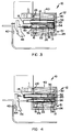
- the circuit breaker 10 includes an electro-magnetically operable device 12, in accordance with the invention.
- the device 12 comprises a coil 13 that defines a cavity.
- a first core 14 and a second core 16 are located within the cavity, adjacent one another.
- the first core 14 is housed in a sealed canister 18 which is filled with a damping liquid.
- the core 14 is displaceable within the canister 18 in a damped manner.
- the second core 16 is also displaceable within the cavity and movement thereof is guided by an open tube 20.
- the coil 13 is wound on a bobbin 22 which defines the cavity.
- the coil 13 may be round or oval.
- the bobbin 22 is mounted on an "L"-shaped stator frame 24 which has a base 26 and a post 28 extending from the base 26.
- the canister 18 projects through a first aperture in the post 28 and the second core 16 projects through a second aperture in the post 28.
- a pole piece 30 is arranged on an opposed side of the bobbin 22 to the post 28.
- the pole piece 30 is separated from the base 26 of the stator frame 24 by an air gap 31.
- the first core 14 is urged away from the pole piece 30 by means of a first helical spring 32 and the second core 16 is urged away from the pole piece 30 by a second helical spring 34.
- the first core 14 and the second core 16 are stepped, having narrow end portions which are received within the springs 32 and 34, respectively. It will be noted that an end 36 of the first core 14 is closer to the pole piece 30 than an end 38 of the second core 16, when the coil 13 is not energised.
- the air gap between the first core 14 and the pole piece 30 is less than the air gap between the second core 16 and the pole piece 30. It will be appreciated by those skilled in the art that, in use, current in the coil 13 will establish flux which will tend to displace the cores 14 and 16 towards the pole piece 30, against the springs 32 and 34.
- the circuit breaker 10 further has an armature 40 which is pivotally displaceable into contact with the free end of the post 28 and the upper end of the pole piece 30.
- the armature 40 is connected to a tripping mechanism (which is not shown) of the circuit breaker 10 in a known manner.
- the circuit breaker 10 has a fixed contact 42 and a moving contact 44.
- the moving contact 44 is carried by a moving contact carrier 46 which is displaceable between a closed or "on” position in which the contacts 42 and 44 are mechanically and electrically in contact (as shown in Figure 1) and an open or “off” position in which the contacts 42 and 44 are spaced apart.
- the moving contact carrier 46 is mechanically connected to the second core 16 by means of a link 50.
- the link 50 is connected to the second core 16 in a lost motion manner, the second core 16 having a slot 52 defined therein.
- the link 50 has a predetermined length and the slot 52 is so arranged that, when the moving contact carrier 46 is in its closed position and there is no current in the coil 13, the end of the link 50 associated with the second core 16 is positioned approximately centrally in the slot 52.
- the moving contact carrier 46 is free to move from its closed position towards its open position and, when the moving contact carrier 46 is in its closed position, the second core 16 can move, a certain extent, towards the pole piece 30 without displacing the contact carrier 46.
- the coil 13 carries the load current of the circuit breaker 10.
- the reluctance of a magnetic circuit formed by the armature 40, the post 28, the first core 14 and the pole piece 30 is significantly decreased, thereby increasing the electro-magnetic force acting on the armature 40.
- This force is large enough to displace the armature 40 into contact with the post 28 and the pole piece 30 (as shown in Figure 3) and thereby operate the tripping mechanism of the circuit breaker 10.
- the tripping mechanism acts on the carrier 46, displacing it from its closed position to an open position (shown in Figure 3). Because the current is not sufficient to displace the second core 16 to a significant extent, the second core 16 remains substantially in its first, normal position. However, because of the lost motion characteristic of the link 50 and the slot 52, the carrier 46 is able to move from its closed position to its open position (as shown in Figure 3).
- the force acting on the second core 16 will be sufficient to displace it into contact with the pole piece 30. It will be appreciated that, although the force acting on the first core 14 will, initially, be greater than that acting on the second core 16, because of the damping effect of the liquid in the canister 18 the second core 16 will move closer to the pole piece 30 faster than the first core 14. When this occurs, because the flux is inversely proportional to the gap, the flux through the second core 16 will become greater than that through the first core 14 so that the force on the second core 16 will be greater than that on the first core 14.
- the high opening speed of the moving contact carrier 46 when there is a large overload current introduces a high resistance to the electric circuit limiting the let-through current and the clearing time of the circuit breaker 10.
- circuit breaker 10 can be varied by varying the strength of the springs 32 and 34 and the air gaps between the cores 14 and 16 and the pole piece 30.
Landscapes
- Physics & Mathematics (AREA)
- Electromagnetism (AREA)
- Breakers (AREA)
- Surgical Instruments (AREA)
- Power Steering Mechanism (AREA)
- Vehicle Body Suspensions (AREA)
- Electrochromic Elements, Electrophoresis, Or Variable Reflection Or Absorption Elements (AREA)
- Manufacturing Of Magnetic Record Carriers (AREA)
- Magnetic Heads (AREA)
- Liquid Crystal (AREA)
Applications Claiming Priority (2)
| Application Number | Priority Date | Filing Date | Title |
|---|---|---|---|
| ZA927005 | 1992-09-14 | ||
| ZA927005 | 1992-09-14 |
Publications (3)
| Publication Number | Publication Date |
|---|---|
| EP0588588A2 true EP0588588A2 (fr) | 1994-03-23 |
| EP0588588A3 EP0588588A3 (fr) | 1994-12-28 |
| EP0588588B1 EP0588588B1 (fr) | 1999-11-17 |
Family
ID=25582109
Family Applications (1)
| Application Number | Title | Priority Date | Filing Date |
|---|---|---|---|
| EP93307208A Expired - Lifetime EP0588588B1 (fr) | 1992-09-14 | 1993-09-13 | Dispositif électromagnétique |
Country Status (5)
| Country | Link |
|---|---|
| US (1) | US5402092A (fr) |
| EP (1) | EP0588588B1 (fr) |
| AT (1) | ATE186794T1 (fr) |
| DE (1) | DE69327026T2 (fr) |
| ZA (1) | ZA936632B (fr) |
Cited By (4)
| Publication number | Priority date | Publication date | Assignee | Title |
|---|---|---|---|---|
| EP0663680A3 (fr) * | 1994-01-17 | 1996-08-28 | Circuit Breaker Ind | Dispositif de commande d'un disjoncteur. |
| FR2772981A1 (fr) * | 1997-12-24 | 1999-06-25 | Schneider Electric Sa | Dispositif de declenchement selectif pour disjoncteur |
| EP1310971A3 (fr) * | 2001-10-18 | 2003-08-20 | Circuit Breaker Industries Limited | Mécanisme de disjoncteur réglable |
| CN105590808A (zh) * | 2016-02-29 | 2016-05-18 | 上海首泓液磁科技有限公司 | 阻尼继电器及其应用 |
Families Citing this family (5)
| Publication number | Priority date | Publication date | Assignee | Title |
|---|---|---|---|---|
| DE10026813B4 (de) * | 1999-06-24 | 2006-01-19 | Abb Patent Gmbh | Elektromagnetischer Auslöser |
| JP2009076371A (ja) * | 2007-09-21 | 2009-04-09 | Nihon Airpax Kk | 回路遮断器 |
| US8049585B2 (en) * | 2009-08-24 | 2011-11-01 | Ford Global Technologies, Llc | Vehicle power system and electrical contactor for use with same |
| CN102208267B (zh) * | 2011-01-14 | 2013-12-18 | 西北核技术研究所 | 感应腔磁芯复位机构 |
| JP6037730B2 (ja) * | 2012-08-31 | 2016-12-07 | 富士通コンポーネント株式会社 | 電磁継電器 |
Family Cites Families (6)
| Publication number | Priority date | Publication date | Assignee | Title |
|---|---|---|---|---|
| US1636953A (en) * | 1924-10-20 | 1927-07-26 | Dreyer Otto | Thermal protective device for electric circuits |
| US2486613A (en) * | 1945-10-19 | 1949-11-01 | Ite Circuit Breaker Ltd | Two-armature selectively retarded electromagnet |
| US2661451A (en) * | 1952-01-26 | 1953-12-01 | Hoover Co | Instantly reversing motor |
| DE2348613C2 (de) * | 1973-09-27 | 1975-11-06 | Siemens Ag, 1000 Berlin Und 8000 Muenchen | Selbstschalter, insbesondere Schutzschalter |
| DE3016467A1 (de) * | 1980-04-29 | 1981-11-05 | Christian Geyer GmbH & Co, 8500 Nürnberg | Elektromagnet fuer selbstschalter |
| GB2117973B (en) * | 1982-04-06 | 1986-01-08 | Matsushita Electric Works Ltd | Circuit protecting sensor |
-
1993
- 1993-09-08 ZA ZA936632A patent/ZA936632B/xx unknown
- 1993-09-13 US US08/120,666 patent/US5402092A/en not_active Expired - Lifetime
- 1993-09-13 EP EP93307208A patent/EP0588588B1/fr not_active Expired - Lifetime
- 1993-09-13 DE DE69327026T patent/DE69327026T2/de not_active Expired - Lifetime
- 1993-09-13 AT AT93307208T patent/ATE186794T1/de not_active IP Right Cessation
Cited By (5)
| Publication number | Priority date | Publication date | Assignee | Title |
|---|---|---|---|---|
| EP0663680A3 (fr) * | 1994-01-17 | 1996-08-28 | Circuit Breaker Ind | Dispositif de commande d'un disjoncteur. |
| FR2772981A1 (fr) * | 1997-12-24 | 1999-06-25 | Schneider Electric Sa | Dispositif de declenchement selectif pour disjoncteur |
| EP0926693A1 (fr) * | 1997-12-24 | 1999-06-30 | Schneider Electric Sa | Dispositif de déclenchement sélectif pour un disjoncteur |
| EP1310971A3 (fr) * | 2001-10-18 | 2003-08-20 | Circuit Breaker Industries Limited | Mécanisme de disjoncteur réglable |
| CN105590808A (zh) * | 2016-02-29 | 2016-05-18 | 上海首泓液磁科技有限公司 | 阻尼继电器及其应用 |
Also Published As
| Publication number | Publication date |
|---|---|
| US5402092A (en) | 1995-03-28 |
| ATE186794T1 (de) | 1999-12-15 |
| ZA936632B (en) | 1994-03-30 |
| EP0588588A3 (fr) | 1994-12-28 |
| EP0588588B1 (fr) | 1999-11-17 |
| DE69327026D1 (de) | 1999-12-23 |
| DE69327026T2 (de) | 2000-06-08 |
Similar Documents
| Publication | Publication Date | Title |
|---|---|---|
| EP0557621B1 (fr) | Disjoncteur | |
| IE54932B1 (en) | Molded case circuit breaker apparatus having trip bar with flexible armature interconnection | |
| EP2251887A1 (fr) | Dispositif de déclenchement électromagnétique | |
| JPS64778B2 (fr) | ||
| EP2091061B1 (fr) | Actionneur de déclenchement incluant une traversée thermoplastique, et unité de déclenchement et appareil de commutation électrique l'incluant | |
| US5162765A (en) | Adjustable magnetic tripping device and circuit breaker including such device | |
| US5402092A (en) | Electro-magnetic device | |
| US5831499A (en) | Selective trip unit for a multipole circuit breaker | |
| US4864261A (en) | Contactor device fo circuit breaker | |
| US4683451A (en) | Circuit breaker with trip delay magnetic circuit | |
| US4267539A (en) | Circuit breaker having a cam for external adjustment of its trip point | |
| US5543766A (en) | Operating device for a circuit breaker | |
| EP0557620A1 (fr) | Interrupteur à soufflage magnétique | |
| EP0181103B1 (fr) | Disjoncteur | |
| JPH05342974A (ja) | 低電流応答特性を有する熱動電磁式トリップユニット | |
| US3441883A (en) | Sensitive electro-magnetic tripping device of the re-setting type | |
| EP0633590B1 (fr) | Disjoncteur électrique | |
| US4129843A (en) | Magnetic trip means for circuit breaker | |
| US3959754A (en) | Circuit breaker with improved trip means | |
| US3337824A (en) | Circuit breaker having dashpot type electro-magnetic core and simplified actuating linkage | |
| US5670922A (en) | Circuit breaker magnetic trip unit | |
| EP0633589A1 (fr) | Mécanisme disjoncteur | |
| US4771254A (en) | Circuit breaker magnetic trip unit | |
| US4521756A (en) | Circuit breaker having increased contact opening velocity at trip operation | |
| KR200212855Y1 (ko) | 배선용 차단기의 전자식 트립코일 기구 |
Legal Events
| Date | Code | Title | Description |
|---|---|---|---|
| PUAI | Public reference made under article 153(3) epc to a published international application that has entered the european phase |
Free format text: ORIGINAL CODE: 0009012 |
|
| AK | Designated contracting states |
Kind code of ref document: A2 Designated state(s): AT DE FR GB IT NL SE |
|
| PUAL | Search report despatched |
Free format text: ORIGINAL CODE: 0009013 |
|
| AK | Designated contracting states |
Kind code of ref document: A3 Designated state(s): AT DE FR GB IT NL SE |
|
| 17P | Request for examination filed |
Effective date: 19950406 |
|
| 17Q | First examination report despatched |
Effective date: 19961223 |
|
| GRAG | Despatch of communication of intention to grant |
Free format text: ORIGINAL CODE: EPIDOS AGRA |
|
| GRAG | Despatch of communication of intention to grant |
Free format text: ORIGINAL CODE: EPIDOS AGRA |
|
| GRAH | Despatch of communication of intention to grant a patent |
Free format text: ORIGINAL CODE: EPIDOS IGRA |
|
| GRAH | Despatch of communication of intention to grant a patent |
Free format text: ORIGINAL CODE: EPIDOS IGRA |
|
| GRAA | (expected) grant |
Free format text: ORIGINAL CODE: 0009210 |
|
| AK | Designated contracting states |
Kind code of ref document: B1 Designated state(s): AT DE FR GB IT NL SE |
|
| PG25 | Lapsed in a contracting state [announced via postgrant information from national office to epo] |
Ref country code: SE Free format text: THE PATENT HAS BEEN ANNULLED BY A DECISION OF A NATIONAL AUTHORITY Effective date: 19991117 |
|
| REF | Corresponds to: |
Ref document number: 186794 Country of ref document: AT Date of ref document: 19991215 Kind code of ref document: T |
|
| ET | Fr: translation filed | ||
| REF | Corresponds to: |
Ref document number: 69327026 Country of ref document: DE Date of ref document: 19991223 |
|
| ITF | It: translation for a ep patent filed | ||
| PLBE | No opposition filed within time limit |
Free format text: ORIGINAL CODE: 0009261 |
|
| STAA | Information on the status of an ep patent application or granted ep patent |
Free format text: STATUS: NO OPPOSITION FILED WITHIN TIME LIMIT |
|
| 26N | No opposition filed | ||
| REG | Reference to a national code |
Ref country code: GB Ref legal event code: IF02 |
|
| PGFP | Annual fee paid to national office [announced via postgrant information from national office to epo] |
Ref country code: IT Payment date: 20090415 Year of fee payment: 17 Ref country code: FR Payment date: 20090430 Year of fee payment: 17 |
|
| PGFP | Annual fee paid to national office [announced via postgrant information from national office to epo] |
Ref country code: NL Payment date: 20090915 Year of fee payment: 17 Ref country code: GB Payment date: 20090916 Year of fee payment: 17 Ref country code: AT Payment date: 20090701 Year of fee payment: 17 |
|
| PGFP | Annual fee paid to national office [announced via postgrant information from national office to epo] |
Ref country code: DE Payment date: 20090430 Year of fee payment: 17 |
|
| REG | Reference to a national code |
Ref country code: NL Ref legal event code: V1 Effective date: 20110401 |
|
| GBPC | Gb: european patent ceased through non-payment of renewal fee |
Effective date: 20100913 |
|
| PG25 | Lapsed in a contracting state [announced via postgrant information from national office to epo] |
Ref country code: IT Free format text: LAPSE BECAUSE OF NON-PAYMENT OF DUE FEES Effective date: 20100913 |
|
| REG | Reference to a national code |
Ref country code: FR Ref legal event code: ST Effective date: 20110531 |
|
| REG | Reference to a national code |
Ref country code: DE Ref legal event code: R119 Ref document number: 69327026 Country of ref document: DE Effective date: 20110401 |
|
| PG25 | Lapsed in a contracting state [announced via postgrant information from national office to epo] |
Ref country code: DE Free format text: LAPSE BECAUSE OF NON-PAYMENT OF DUE FEES Effective date: 20110401 Ref country code: FR Free format text: LAPSE BECAUSE OF NON-PAYMENT OF DUE FEES Effective date: 20100930 |
|
| PG25 | Lapsed in a contracting state [announced via postgrant information from national office to epo] |
Ref country code: AT Free format text: LAPSE BECAUSE OF NON-PAYMENT OF DUE FEES Effective date: 20100913 Ref country code: GB Free format text: LAPSE BECAUSE OF NON-PAYMENT OF DUE FEES Effective date: 20100913 Ref country code: NL Free format text: LAPSE BECAUSE OF NON-PAYMENT OF DUE FEES Effective date: 20110401 |