EP0588664A2 - Procédé de stabilisation d'un échantillon - Google Patents
Procédé de stabilisation d'un échantillon Download PDFInfo
- Publication number
- EP0588664A2 EP0588664A2 EP93307371A EP93307371A EP0588664A2 EP 0588664 A2 EP0588664 A2 EP 0588664A2 EP 93307371 A EP93307371 A EP 93307371A EP 93307371 A EP93307371 A EP 93307371A EP 0588664 A2 EP0588664 A2 EP 0588664A2
- Authority
- EP
- European Patent Office
- Prior art keywords
- sample
- core
- liner
- container
- sample core
- Prior art date
- Legal status (The legal status is an assumption and is not a legal conclusion. Google has not performed a legal analysis and makes no representation as to the accuracy of the status listed.)
- Withdrawn
Links
Images

Classifications
-
- E—FIXED CONSTRUCTIONS
- E21—EARTH OR ROCK DRILLING; MINING
- E21B—EARTH OR ROCK DRILLING; OBTAINING OIL, GAS, WATER, SOLUBLE OR MELTABLE MATERIALS OR A SLURRY OF MINERALS FROM WELLS
- E21B25/00—Apparatus for obtaining or removing undisturbed cores, e.g. core barrels or core extractors
- E21B25/08—Coating, freezing, consolidating cores; Recovering uncontaminated cores or cores at formation pressure
-
- G—PHYSICS
- G01—MEASURING; TESTING
- G01N—INVESTIGATING OR ANALYSING MATERIALS BY DETERMINING THEIR CHEMICAL OR PHYSICAL PROPERTIES
- G01N1/00—Sampling; Preparing specimens for investigation
- G01N1/28—Preparing specimens for investigation including physical details of (bio-)chemical methods covered elsewhere, e.g. G01N33/50, C12Q
-
- G—PHYSICS
- G01—MEASURING; TESTING
- G01N—INVESTIGATING OR ANALYSING MATERIALS BY DETERMINING THEIR CHEMICAL OR PHYSICAL PROPERTIES
- G01N2203/00—Investigating strength properties of solid materials by application of mechanical stress
- G01N2203/02—Details not specific for a particular testing method
- G01N2203/026—Specifications of the specimen
- G01N2203/0284—Bulk material, e.g. powders
-
- G—PHYSICS
- G01—MEASURING; TESTING
- G01N—INVESTIGATING OR ANALYSING MATERIALS BY DETERMINING THEIR CHEMICAL OR PHYSICAL PROPERTIES
- G01N2203/00—Investigating strength properties of solid materials by application of mechanical stress
- G01N2203/02—Details not specific for a particular testing method
- G01N2203/026—Specifications of the specimen
- G01N2203/0298—Manufacturing or preparing specimens
Definitions
- the present invention relates generally to the preparation of core samples for non-destructive analysis.
- Computed tomography commonly known in the medical field as CAT scanning (computerized axial tomography or computer assisted tomography), is a non-destructive analysis technology that provides an image of the internal structure and composition of an object.
- CT Computed tomography
- CAT scanning computerized axial tomography or computer assisted tomography
- images can be obtained which represent cross-sectional axial or longitudinal slices through the object.
- Each image is produced through the reconstruction of a matrix of x-ray attenuation coefficients by a dedicated computer.
- the images reflect volume by volume (voxel) electron density variations displayed as gray levels of contrasting CT numbers.
- Computed tomography and other non-destructive analysis techniques are used in the petroleum industry for analyzing sample cores in order to determine subterranean formation properties.
- computed tomography electron density variations over an axial or longitudinal slice of a core sample can be determined and displayed. Additionally, a three-dimensional tomographic representation of the sample core can be obtained by compositing CT data for a series of discrete parallel slices of the sample core.
- CT analysis has been used for: examining core structure, core mineral distribution, and core porosity distribution; studying natural and induced formation fractures; selecting plug samples; conducting multiphase core flow displacement experiments; conducting acidizing studies; evaluating formation damage; evaluating in situ formation stress; and conducting core flooding experiments.
- the sample core When a sample core must be retrieved from a formation which is friable, soft, fractured, and/or unconsolidated, the sample core will typically be obtained using an apparatus composed of: a sample barrel (or sample tube); a liner positioned inside the sample barrel; and a coring bit positioned at the end of the sample barrel. As the sample core is cut from the formation by the coring bit, it is delivered into the liner. The presence of the sample barrel liner ensures better core recovery and sample quality, alleviates core jamming problems, and prevents core damage. Unfortunately, when the sample core is positioned in the liner, a small void space (i.e., an annulus) will exist between the exterior of the sample core and the interior wall of the liner.
- a small void space i.e., an annulus
- the liner having the sample core contained therein is removed from the sample barrel and then marked in order to indicate formation depth.
- the liner and the sample core contained therein are then cut into longitudinal sections suitable for handling and for use in laboratory analysis. After cutting, caps are secured to the ends of the liner sections in order to seal the liner sections and to prevent the core material from falling out of the liner sections.
- the sealed liner sections protect the core material from atmospheric conditions and from physical blows and impacts.
- the sample barrel liner will typically be formed from a material which will allow the undisturbed sample core contained therein to be analyzed using non-destructive techniques such as computed tomography, core gamma logging, and x-ray radiography. Examples of commonly used liner materials include aluminum and fiberglass.
- a CT scanning system used for analyzing lined sample cores will typically include: an x-ray tube which provides a collimated x-ray beam; a detector array which (a) receives the x-ray beam after it passes through the sample core and (b) provides a scanning output signal; a means for either rotating and repositioning the sample core with respect to the x-ray tube and detector array or for rotating and repositioning the x-ray tube and detector array with respect to the sample core such that the CT scanning system will operate to thoroughly scan one or a series of slices extending through the sample core; and a dedicated computer which controls scanner functions, processes the scanning information received from the detector array, and generates image reconstructions of the sample core slices.
- Each CT scanning slice will typically have a thickness of 2 mm.
- the slice is first divided into volume elements (voxels) typically having dimensions of 0.25 mm x 0.25 mm x 2.0 mm.
- an average material CT number N CT is calculated for each of the volume elements of the scan slice.
- N CT CT number
- HU Hounsfield units
- the overall MAC of the volume element will be determined by the mass weighted average of the mass attenuation coefficients of the individual materials contained in the volume element.
- a two-dimensional video image of the slice can be obtained by (a) relating the CT number values obtained for each voxel of the slice to values on the linear scale ranging from black to white (i.e., the gray scale) and then (b) causing the individual volume elements of the slice to correspond with the individual picture dot elements (i.e., pixels) of the video image.
- the gray scale values obtained in step (a) can be converted to values on the linear red scale.
- the general material composition distribution of a CT scanning slice will typically be determined by displaying the slice as it relates to either the overall gray scale or the overall red scale. After the material composition distribution of the slice is determined, the density of each portion of the slice can be determined by examining the slice as it relates to narrower portions of either the gray scale or the linear red scale. For a given mineral composition, a higher CT number will generally indicate a higher density and a lower porosity.
- a significant problem encountered in the CT analysis of samples cores involves the occurrence of x-ray beam hardening.
- the lower energy photons of the beam are absorbed much more rapidly than are the beam's higher energy photons. Consequently, the average energy of the beam increases-(i.e., the beam is hardened) as it travels through the sample core due to the fact that a high relative proportion of the beam's low energy photons are quickly absorbed in the initial outer region of the core.
- the rapid initial absorption of low energy photons in the outer region of the sample core also yields a beam hardening artifact which cloaks the outer region of the CT image.
- the beam hardening artifact will appear as a lower gray scale area.
- the beam hardening artifact will resemble a lighter halo which fades continuously from the outer region of the CT image toward the center of the CT image and thus produces a bull's-eye-like visual effect.
- a CT image including a beam hardening artifact 2 is illustrated in Figure 1.
- a corresponding CT image which has been corrected to remove the beam hardening artifact 2 is shown in Figure 2.
- Beam hardening artifact 2 is light in color.
- the appearance of a light color would normally indicate the presence of a region having a high relative electron density.
- the artifact cquld be mistakenly interpreted as merely indicating a very high density sample region.
- the artifact obscures the actual features of the outer region of the core such that these features cannot be readily viewed and analyzed.
- the beam hardening artifact can introduce a substantial amount of error into the statistical CT number analysis of the CT scanning data.
- beam hardening artifacts can be at least partially filtered out during CT image reconstruction by means of an imaging software correction.
- such corrections typically do not completely eliminate the effects of beam hardening.
- the precise beam hardening corrections necessary for a given sample core will depend upon the actual material composition of the sample core and the condition of the sample core. Thus, the composition and condition of a sample core must be known in advance in order for proper beam hardening corrections to be made.
- the present invention provides a method of stabilizing a sample core in a container which comprises said sample in the container such that there is a space between at least a portion of the length of said sample and an inner wall of the container, and passing a flowable solid stabilizing material into said space.
- the method comprises the steps of: (a) elevating a first end of the liner; (b) pouring a flowable solid stabilizing material into the first end of the liner; and (c) packing the stabilizing material along the length of the sample core between the exterior of the core and the inner wall of the liner.
- the present invention further provides a method of analyzing an elongate sample core using a non-destructive analyzing procedure, wherein during the analysing step, the core is stabilized in an elongate sample container by the method of the invention.
- the annulus existing between the exterior of the core sample and the interior wall of the liner, as well as other void spaces within the sample core itself is packed with a flowable solid stabilizer material.
- a surprisingly thorough degree of stabilizer material packing is achieved along the entire length of the sample core.
- the stabilizer material packing operates to prevent the sample core from breaking and/or moving within the liner. Additionally, the stabilizer material will not hinder the removal of the sample core from the liner. Further, the stabilizer material alleviates the beam hardening problems discussed hereinabove by (a) filling the annulus between the exterior of the sample core and the interior wall of the liner, (b) filling other void spaces within the sample core itself. and (c) prefiltering the CT scanning beam before it enters the outer region of the sample core.
- Figure 1 illustrates a CT scanning image including a beam hardening artifact 2.
- Figure 2 illustrates a corrected CT scanning image wherein beam hardening artifact 2 is removed.
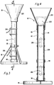
- Figure 3 provides an elevational side view of a packing system 8 useful in conducting the core stabilization method of the invention.
- Figure 4 provides a cutaway elevational side view of packing system 8 of Figure 3.
- the inventive core stabilization method is particularly well-suited for use in stabilizing lined sample cores (i.e., sample cores held in sample liners).
- a sample liner having a sample core contained therein is first removed from the sample barrel or sample tube of a coring apparatus and then cut into workable sections for laboratory analysis. Each section will typically be five feet or less in length. Next, each of these lined sections is stabilized in accordance with the inventive method.
- a lined sample core section 10 including a liner 12 and a sample core 14 is preferably stabilized in accordance with the inventive method by placing a cap 16 on one end of section 10 and then raising the other end of section 10 such that section 10 is placed in a substantially vertical position.
- a receptacle 18 or similar device is preferably used to hold section 10 in vertical position.
- a cone-shaped feeder 20 is preferably positioned on the open upper end of section 10.
- a flowable solid stabilizer material 22 is then poured into or otherwise placed in cone feeder 20 such that the stabilizer material is allowed to flow into the annulus 24 existing between the exterior of the sample core and the inner wall of the sample liner.
- lined sample core section 10 is preferably agitated in order to cause the stabilizer material 22 in cone feeder 20 to flow into and become packed in annulus 24.
- the agitation of the lined sample core also causes the stabilizer material 22 to flow into and become packed in void spaces existing within the sample core itself.
- the lined sample core can be agitated in accordance with the inventive method by manually tapping the sample liner, by positioning strap-on ultrasonic vibrators 26 on the sample liner, or by other comparable means.
- cone feeder 20 is removed from the open upper end of lined section 10 and a cap, substantially identical to cap 16, is placed on said open upper end. These caps operate to seal lined section 10 such that sample core 14 is held in liner 12 and is protected from atmospheric conditions.
- lined section 10 can be readily analyzed using various non-destructive analysis techniques. Examples of such techniques include CT scanning, core gamma logging, and x-ray radiography. Stabilized section 10 is preferably analyzed using a computed tomography technique of the type described hereinabove.
- the inventive core stabilization method provides a surprisingly thorough degree of packing along the entire length of the sample core.
- the packed stabilizer material supports and protects the sample core within the sample liner such that the sample core is prevented from moving and breaking within the liner.
- the stabilizer material also greatly reduces the effects of beam hardening during CT scanning and otherwise improves CT image resolution by: (a) acting as a beam prefilter which filters (i.e., prehardens) the beam before it penetrates the exterior of the sample core; (b) filling void spaces within the lined sample such that the degree of attenuation that would otherwise occur as the beam travels between alternating regions of very high and very low density is reduced; and (c) reducing the image contrast which would otherwise exist between the gas and/or air filled void spaces and the core.
- the sample liner used in conjunction with the inventive core stabilization method is preferably formed from a material which will allow an undisturbed sample core contained therein to be analyzed by CT scanning and/or by other non-destructive core analysis techniques.
- suitable liner materials include aluminum and fiberglass.
- the flowable solid stabilizer material used in the inventive core stabilization method is preferably a material which (a) will readily flow into and pack the void spaces in the lined sample, (b) has a low mean atomic number relative to the mean atomic number of the core material, and (c) has a material bulk density which is not significantly greater than, and is preferably equal to or less than, the material density of the core material. Such materials will not be visible (i.e., will appear black) in most gray scale or linear red scale CT images. Most preferably, the stabilizer material used in the inventive method has a CT number not exceeding about 1000.
- the stabilizer material is preferably a material which will not affect the native state properties (e.g., wettability, saturations, gamma ray response, etc.) of the sample core and which will not interfere with the removal of the sample core from the liner.
- native state properties e.g., wettability, saturations, gamma ray response, etc.
- stabilizer materials preferred for use in the inventive method include plastic beads (e.g., polypropylene beads) and quartz sand.
- the stabilizer material In order to fill fractures and other voids in a lined sample core, the stabilizer material must include at least some particles which will physically fit into these voids (i.e., the stabilizer material must include at least some particles which are smaller than the voids themselves).
- the particle size of the stabilizer material used on any given case can be changed as necessary to obtain a desired degree of packing.
- the stabilizer material presently preferred for use in the inventive method is rounded and highly sorted quartz sand consisting of particles having sizes of between about 20 and 40 mesh. 20-40 mesh rounded quartz sand has a bulk density which is close to or slightly less than the densities of most solid formation materials.
- a friable, location oriented, devonian shale sample core was obtained using a core cutting apparatus comprising a coring bit, a sample barrel, and an aluminum sample barrel liner.
- the sample core had a diameter of four inches.
- an air mist coring fluid was used during the core cutting operation.
- sample liner having the sample core contained therein was removed from the sample barrel.
- the sample liner was then marked for depth and cut into segments of four feet in length. Each segment was stabilized in accordance with the inventive core stabilization method using well rounded and highly sorted 20-40 mesh quartz sand.
- one end of the lined sample segment was first capped with a rubber end cap.
- the lined sample segment was then placed in vertical position such that its capped end was on bottom and its open end was on top.
- a cone-shaped feeder was positioned on the open end of the lined sample segment.
- the stabilizer material was poured into the cone feeder and the exterior of the lined sample segment was repeatedly tapped with a hammer. This packing procedure was continued until the stabilizer material stopped flowing into the lined sample segment.
- the cone feeder was removed from the open end of the lined sample segment and said open end was capped with a rubber end cap.
- the packed sample core was then transported to a laboratory for CT analysis.
- the CT apparatus used for analyzing the packed sample core segments included a fourth generation TECHNICARE 2060 scanner coupled with a micro VAX 3900 computer having special hardware for CT image display.
- the CT apparatus operated with an x-ray tube voltage of 120 KVp, a scanning slice thickness of 2 mm, a scanning diameter of 12.5 cm, and a slice spacing of 2 inches.
- the CT apparatus provided a 512 x 512 image with each pixel thereof representing a scanning slice volume element having the dimensions of 0.25 mm x 0.25 mm x 2.0 mm.
- the CT image was adjusted to allow the display of air or gas filled void spaces and of stabilization material filled spaces within the packed core segments.
- the CT scanning images also revealed that the stabilization material used in the inventive method had surrounded and thereby preserved areas of natural breakage and rubblization within the sample core. Typically, such areas would otherwise become shifted and chaotically arranged within the liner during handling and transport.
- the CT scanning results additionally showed that, as revealed by the consistent alignment of core fractions with scribe marks placed on the liner following retrieval, the packed stabilizer material substantially prevented the sample core from shifting and rolling within the liner during transport and handling. Further, the packed stabilizer material substantially improved the CT imaging response of the sample core segments by greatly reducing the amount of beam hardening artifact generated during the scanning procedure.
Landscapes
- Life Sciences & Earth Sciences (AREA)
- Geology (AREA)
- Engineering & Computer Science (AREA)
- Physics & Mathematics (AREA)
- Mining & Mineral Resources (AREA)
- Geochemistry & Mineralogy (AREA)
- Fluid Mechanics (AREA)
- General Life Sciences & Earth Sciences (AREA)
- Environmental & Geological Engineering (AREA)
- Health & Medical Sciences (AREA)
- Chemical & Material Sciences (AREA)
- Analytical Chemistry (AREA)
- Biochemistry (AREA)
- General Health & Medical Sciences (AREA)
- General Physics & Mathematics (AREA)
- Immunology (AREA)
- Pathology (AREA)
- Analysing Materials By The Use Of Radiation (AREA)
Applications Claiming Priority (2)
| Application Number | Priority Date | Filing Date | Title |
|---|---|---|---|
| US94705792A | 1992-09-18 | 1992-09-18 | |
| US947057 | 1992-09-18 |
Publications (2)
| Publication Number | Publication Date |
|---|---|
| EP0588664A2 true EP0588664A2 (fr) | 1994-03-23 |
| EP0588664A3 EP0588664A3 (en) | 1995-09-13 |
Family
ID=25485444
Family Applications (1)
| Application Number | Title | Priority Date | Filing Date |
|---|---|---|---|
| EP93307371A Withdrawn EP0588664A3 (en) | 1992-09-18 | 1993-09-17 | Sample core stabilization |
Country Status (3)
| Country | Link |
|---|---|
| EP (1) | EP0588664A3 (fr) |
| AU (1) | AU4744893A (fr) |
| NO (1) | NO933291L (fr) |
Cited By (10)
| Publication number | Priority date | Publication date | Assignee | Title |
|---|---|---|---|---|
| WO1997026441A1 (fr) * | 1996-01-15 | 1997-07-24 | Baroid Technology, Inc. | Fluide lubrifiant pour une carotte et utilisation de celui-ci |
| US6520033B1 (en) * | 2000-03-29 | 2003-02-18 | Her Majesty The Queen In Right Of Canada, Represented By The Minister Of The Environment | Apparatus for sampling & analysis of thermally-labile species and a method relating thereto |
| DE102005005518A1 (de) * | 2005-02-01 | 2006-08-10 | Eberhard-Karls-Universität Tübingen Universitätsklinikum | Einführvorrichtung für biologische Proben |
| EP1992781A3 (fr) * | 2007-05-14 | 2011-03-09 | Kirk Petrophysics Limited | Améliorations de ou liées à la stabilisation d'un échantillon |
| CN102914459A (zh) * | 2012-10-16 | 2013-02-06 | 绍兴文理学院 | 一种液压式三轴试样制样器及其制样方法 |
| CN104502180A (zh) * | 2014-12-09 | 2015-04-08 | 河海大学 | 天然硅石材料在制作透明岩石和透明岩体中的应用 |
| CN106442115A (zh) * | 2016-09-18 | 2017-02-22 | 中国科学院、水利部成都山地灾害与环境研究所 | 复杂应力下岩石节理超声实验装置及其控制系统 |
| WO2017123111A1 (fr) * | 2016-01-14 | 2017-07-20 | Эвербрайт Инновейшнс Лимитед | Procédé pour mesurer le volume intérieur d'un objet |
| US10428611B2 (en) | 2017-12-27 | 2019-10-01 | Saudi Arabian Oil Company | Apparatus and method for in-situ stabilization of unconsolidated sediment in core samples |
| US12510495B2 (en) | 2022-12-14 | 2025-12-30 | Rolls-Royce Plc | Method of scanning a component embedded in a granular material using computed tomography |
Families Citing this family (1)
| Publication number | Priority date | Publication date | Assignee | Title |
|---|---|---|---|---|
| CN103389238B (zh) * | 2013-08-05 | 2015-10-28 | 中国海洋石油总公司 | 混砂岩样制作装置 |
Family Cites Families (5)
| Publication number | Priority date | Publication date | Assignee | Title |
|---|---|---|---|---|
| GB1005557A (en) * | 1964-06-08 | 1965-09-22 | Rolls Royce | Improvements in or relating to packing of test-pieces during tomography |
| US4419314A (en) * | 1981-05-26 | 1983-12-06 | Core Laboratories, Inc. | Method of coating core samples |
| JPS60181640A (ja) * | 1984-02-29 | 1985-09-17 | Nippon Steel Corp | 工業用放射線断層撮影方法 |
| US4710946A (en) * | 1985-08-06 | 1987-12-01 | Amoco Corporation | Method and apparatus for X-ray video fluoroscopic analysis of rock samples |
| US5027379A (en) * | 1990-02-22 | 1991-06-25 | Bp America Inc. | Method for identifying drilling mud filtrate invasion of a core sample from a subterranean formation |
-
1993
- 1993-09-15 NO NO933291A patent/NO933291L/no unknown
- 1993-09-17 AU AU47448/93A patent/AU4744893A/en not_active Abandoned
- 1993-09-17 EP EP93307371A patent/EP0588664A3/en not_active Withdrawn
Cited By (17)
| Publication number | Priority date | Publication date | Assignee | Title |
|---|---|---|---|---|
| WO1997026441A1 (fr) * | 1996-01-15 | 1997-07-24 | Baroid Technology, Inc. | Fluide lubrifiant pour une carotte et utilisation de celui-ci |
| BE1009967A5 (fr) * | 1996-01-15 | 1997-11-04 | Baroid Technology Inc | Fluide lubrifiant pour une carotte et utilisation de celui-ci. |
| US6520033B1 (en) * | 2000-03-29 | 2003-02-18 | Her Majesty The Queen In Right Of Canada, Represented By The Minister Of The Environment | Apparatus for sampling & analysis of thermally-labile species and a method relating thereto |
| DE102005005518A1 (de) * | 2005-02-01 | 2006-08-10 | Eberhard-Karls-Universität Tübingen Universitätsklinikum | Einführvorrichtung für biologische Proben |
| EP1992781A3 (fr) * | 2007-05-14 | 2011-03-09 | Kirk Petrophysics Limited | Améliorations de ou liées à la stabilisation d'un échantillon |
| US7934569B2 (en) | 2007-05-14 | 2011-05-03 | Kirk Petrophysics Limited | Core stabilization |
| CN102914459A (zh) * | 2012-10-16 | 2013-02-06 | 绍兴文理学院 | 一种液压式三轴试样制样器及其制样方法 |
| CN102914459B (zh) * | 2012-10-16 | 2014-10-29 | 绍兴文理学院 | 一种液压式三轴试样制样器及其制样方法 |
| CN104502180A (zh) * | 2014-12-09 | 2015-04-08 | 河海大学 | 天然硅石材料在制作透明岩石和透明岩体中的应用 |
| WO2017123111A1 (fr) * | 2016-01-14 | 2017-07-20 | Эвербрайт Инновейшнс Лимитед | Procédé pour mesurer le volume intérieur d'un objet |
| CN108449947A (zh) * | 2016-01-14 | 2018-08-24 | 光大创新有限公司 | 一种测量物体内部体积的方法 |
| CN106442115A (zh) * | 2016-09-18 | 2017-02-22 | 中国科学院、水利部成都山地灾害与环境研究所 | 复杂应力下岩石节理超声实验装置及其控制系统 |
| CN106442115B (zh) * | 2016-09-18 | 2024-02-13 | 中国科学院、水利部成都山地灾害与环境研究所 | 复杂应力下岩石节理超声实验装置及其控制系统 |
| US10428611B2 (en) | 2017-12-27 | 2019-10-01 | Saudi Arabian Oil Company | Apparatus and method for in-situ stabilization of unconsolidated sediment in core samples |
| US10641055B2 (en) | 2017-12-27 | 2020-05-05 | Saudi Arabian Oil Company | Apparatus and method for in-situ stabilization of unconsolidated sediment in core samples |
| US10774605B2 (en) | 2017-12-27 | 2020-09-15 | Saudi Arabian Oil Company | Apparatus and method for in-situ stabilization of unconsolidated sediment in core samples |
| US12510495B2 (en) | 2022-12-14 | 2025-12-30 | Rolls-Royce Plc | Method of scanning a component embedded in a granular material using computed tomography |
Also Published As
| Publication number | Publication date |
|---|---|
| NO933291D0 (no) | 1993-09-15 |
| EP0588664A3 (en) | 1995-09-13 |
| AU4744893A (en) | 1994-03-24 |
| NO933291L (no) | 1994-03-21 |
Similar Documents
| Publication | Publication Date | Title |
|---|---|---|
| EP0588664A2 (fr) | Procédé de stabilisation d'un échantillon | |
| Colletta et al. | Computerized X-ray tomography analysis of sandbox models: Examples of thin-skinned thrust systems | |
| Verhelst et al. | X-ray computerized tomography: determination of heterogeneities in rock samples | |
| CN101403711B (zh) | 液态物品检查方法和设备 | |
| EP1579245B1 (fr) | Unites d'exploration par rayonnement comprenant une plate-forme mobile | |
| Hunt et al. | Computed tomography as a core analysis tool: Applications, instrument evaluation, and image improvement techniques | |
| CN101403710B (zh) | 液态物品检查方法和设备 | |
| CN104374682B (zh) | 一种岩心ct扫描分析方法及装置 | |
| US5109398A (en) | Vertical core flow testing apparatus and method with computed tomography scanning | |
| Jacobs et al. | Principles of computerised X-ray tomography and applications to building materials | |
| CN102608135B (zh) | 在危险品检查系统中确定ct扫描位置的方法和设备 | |
| CN102095663B (zh) | 液态物品检查方法和设备 | |
| Coles et al. | Applications of CAT scanning for oil and gas production | |
| CN102162798B (zh) | 液态物品检查方法和设备 | |
| Zeck et al. | Ion microprobe U–Pb zircon geochronology of a late tectonic granitic–gabbroic rock complex within the Hercynian Iberian belt | |
| CN102095664B (zh) | 液态物品检查方法和设备 | |
| CN102147376B (zh) | 液态物品检查方法和设备 | |
| CN102435620A (zh) | 液态物品检查方法和设备 | |
| Macke et al. | 3D-laser-scanning technique applied to bulk density measurements of Apollo lunar samples | |
| Siddiqui | Some Useful Guidelines for Whole Core CT-Scanning for Petrophysical Applications | |
| CN102590239A (zh) | 在毒品检查系统中确定ct扫描位置的方法和设备 | |
| CN102095665B (zh) | 液态物品检查方法和设备 | |
| Crabeck et al. | Imaging air volume fraction in sea ice using non-destructive X-ray tomography. | |
| CN102565102B (zh) | 液态物品检查方法和设备 | |
| Reimers et al. | Characterization of radioactive waste packages by computerized tomography |
Legal Events
| Date | Code | Title | Description |
|---|---|---|---|
| PUAI | Public reference made under article 153(3) epc to a published international application that has entered the european phase |
Free format text: ORIGINAL CODE: 0009012 |
|
| AK | Designated contracting states |
Kind code of ref document: A2 Designated state(s): DE GB NL |
|
| PUAL | Search report despatched |
Free format text: ORIGINAL CODE: 0009013 |
|
| AK | Designated contracting states |
Kind code of ref document: A3 Designated state(s): DE GB NL |
|
| STAA | Information on the status of an ep patent application or granted ep patent |
Free format text: STATUS: THE APPLICATION IS DEEMED TO BE WITHDRAWN |
|
| 18D | Application deemed to be withdrawn |
Effective date: 19960401 |