EP0589070A1 - Système d'ordinateur et procédé pour stocker et afficher un diagramme sémantique structuré entités relationelles - Google Patents
Système d'ordinateur et procédé pour stocker et afficher un diagramme sémantique structuré entités relationelles Download PDFInfo
- Publication number
- EP0589070A1 EP0589070A1 EP92116044A EP92116044A EP0589070A1 EP 0589070 A1 EP0589070 A1 EP 0589070A1 EP 92116044 A EP92116044 A EP 92116044A EP 92116044 A EP92116044 A EP 92116044A EP 0589070 A1 EP0589070 A1 EP 0589070A1
- Authority
- EP
- European Patent Office
- Prior art keywords
- entity
- kernel
- sets
- attributive
- entity sets
- Prior art date
- Legal status (The legal status is an assumption and is not a legal conclusion. Google has not performed a legal analysis and makes no representation as to the accuracy of the status listed.)
- Withdrawn
Links
Images




Classifications
-
- G—PHYSICS
- G06—COMPUTING OR CALCULATING; COUNTING
- G06F—ELECTRIC DIGITAL DATA PROCESSING
- G06F16/00—Information retrieval; Database structures therefor; File system structures therefor
- G06F16/20—Information retrieval; Database structures therefor; File system structures therefor of structured data, e.g. relational data
- G06F16/28—Databases characterised by their database models, e.g. relational or object models
- G06F16/284—Relational databases
- G06F16/288—Entity relationship models
Definitions
- This invention relates to a method for storing of an entity relationship diagram in a computer system, to a method for displaying of an entity relationship diagram on the display of a computer system and to a computer system for displaying of an entity relationship diagram.
- the point of departure of the present invention is the entity relationship model as described in ACM Transactions on Data Based Systems, Volume 1, No. 1 March 1976, Peter Pin-Shan Chen "The Entity-Relationship Model - Toward a Unified View of Data", pages 9 - 36.
- the entity-relationship model proposed by Chen is a data model. This model incorporates some of the important semantic information about the real world serving as a tool for data based design. The corresponding diagrammatic technique proposed by Chen is not optimal.
- the invention is particularly aimed to reduce the redundancy of information shown in the incarnation of an entity relationship diagram so that improved storing and displaying thereof is accomplished.
- the invention particularly provides for a novel diagrammatic technique to represent an entity relationship model.
- An entity relationship diagram according to the invention is characterized by the following principles:
- the kernel entity sets K i are closed information objects.
- the internal structure of these objects preferably is further specified by role and/or attributive entity sets. No direct relations among role or attributive entity sets are allowed regardless whether they belong to the same or different kernel entity sets K i .
- the entity relationship diagram according to the invention does not comprise any redundant information, since relations are only allowed between kernel entity sets K i .
- first and second data are stored.
- the first data is representative of a sequence of kernel entity sets K i
- the second data is representative of relation entity sets R i .
- the second data comprise information as to the assignment of each of the relation entity sets R i to at least one of the kernel entity sets K i . Therefore, it is not necessary to store the absolute positions of the entity sets in the entity relationship diagram of the invention.
- the computer reconstructs automatically the entity relationship diagram from the information stored as to the types of individual entity sets and their assignment to each other. This results in a smaller amount of storage locations needed to store the diagram.
- inventive method for storing is advantageous, since - as compared to prior art method - less storage space is needed. Further the inventive method requires only two data sets - the first and the second data - so that this method is easily implemented.
- the invention provides a method for displaying of the entity relationship diagram on the display of a computer system.
- the display is logically partitioned into at least a first and a second section.
- This step of partitioning preferably is carried out by logically dividing the display into two sections along a horizontal or vertical line.
- the position of this partitioning line is preferably inputted by special input means, such as a mouse.
- the kernel entity sets K i of the entity relationship diagram of the invention are displayed in the first section of the display - such as the lower section, if the display is partitioned by a horizontal line.
- the kernel entity sets K i are represented by a first class of symbols. These symbols are displayed in order to indicate the kernel entity sets K i on the display.
- relation entity sets R i are displayed in the second section of the display.
- the relation entity sets R i are represented by a second class of symbols on the display.
- the entity relation diagram of the invention does not comprise redundant information. This is due to the specific definition of different classes of entity sets and their allowed interrelations.
- the inventive method for displaying is particularly advantageous in that a smaller storage space is required for storing of the entity relationship diagram in the computer system. Further the density of the information displayed on the display of the computer system is increased because of that redundancy free entity relationship diagram. This has the further technical advantage that much more information is displayed on a display of the same size as compared to the prior art. This is also beneficial in that screen scrolling or zooming functions need to be used less frequently because of the higher density of the information displayed and the elimination of redundant information.
- an entity relationship diagram displayed according to the inventive method for displaying is easily modifiable or may even be merged with another entity relationship diagram according to the invention. This is because of the logical partitioning of the display and the particular definition of the entity sets and their interrelations.
- the invention makes it possible to add additional entity sets to an existing entity relationship diagram without manual modification of the existing diagram. If the symbols representing the different classes of entity sets, such as kernel entity sets K i , relation entity sets R i , role entity sets P i and attributive entity sets A i are arranged in an array of allowable positions on the display, the inventive entity relationship diagram becomes even more readily intelligible and modifiable.
- the entity relationship diagram of the invention is a vectorgraph. That is that the absolute coordinates relative to the display of the computer system of the symbols to be displayed are stored. This may be done by means of a computer aided software engineering tool, such as the "application development workbench” by KnowledgeWare Inc. which belongs to the AD/Cycle application development toolset.
- the inventive method for storing of the entity relationship diagram in the inventive method for displaying. This is because less storage space is needed in this case. Further any modifications of the entity relationship diagram to be displayed are more easily performed, if the inventive method for storing is employed.
- semantic information is stored, not only the absolute coordinates of the symbols to be displayed. This semantic information may comprise the relative positions of the entities to be displayed relative to each other. Therefore entity sets are easily insertable or erasable from the diagram. If for example the first data represent a sequence of kernel entity sets K i displayed along a horizontal or vertical line an arbitrary kernel entity set K i is easily insertable in or erasable from that line. This is accomplished by specifying the relative position of the additional kernel entity set K a relative to a neighboring kernel entity set K i The semantic information comprised in the first and the second data allows the computer to generate the entity relationship diagram automatically based on that information.
- the invention further provides for a computer system for displaying of an entity relationship diagram.
- the computer system particularly comprises means for generating the symbols which represent the different classes of entity sets on the display, whereby these means for generating are interconnected to the means for storing of data representative of the different classes of entity sets. Again it is particularly advantageous to store the data representative of the different entity sets according to the inventive method for storing.
- the invention is applicable in different environments.
- the invention is advantageously applied in the repository application generator disclosed in EP-A-0 438 843, in the knowledge based systems disclosed in WO 89/09970, in the computer-aided software engineering facility disclosed in WO 91/08543 as well as in the software distribution system disclosed in WO 91/08542.
- the invention supports the implementation of a relational or object-oriented data base for storing of instances of the entity sets of the entity relationship diagram.
- the inventive diagrammatic technique is also used in the development of software, such as application software.
- the software development is carried out computer aided and thus at least semi-automatically. This is because of the semantic information which is carried in the entity relationship diagram which makes it possible to employ e.g. a knowledge base or an expert system in order to facilitate and speed up software development.
- the invention is further particularly advantageous because re-useability of software modules, such as subroutines or application programs, is enhanced. This is accomplished because of the particular definition of the entity sets according to the invention. If there is a particular software module available which carries out a specific function on the entities comprised in a kernel entity set, this module is re-usable for different subclasses of entities belonging to different attributive or role entity sets of the same kernel entity set.
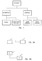
- object-oriented data-analysis implies that the structure to be analyzed is split up in a number of entities. The interrelationship between these entities is analyzed. This results in a hierarchical structure. The entities are arranged on different levels of the hierarchical structure. Entities on lower levels of hierarchy have the same properties than those situated on higher levels of the hierarchy, if there is an interrelationship between a lower level entity and a higher level entity. This results in redundancy free data modelling and data storage, if those attributes which are common to a group of entities are always assigned to the highest level entity possible.
- Fig. 1 concerns the analysis of structures comprising a plurality of different document types.
- the entity "document” which is shown on top of the diagram and which does thus have the highest hierarchical order may comprise attributes such as document number and document title. Those attributes are "inherited” by the lower level entities “description” and “contract” which are placed one level below the entity document. The same applies analogously for the entities of the lowest level of the hierarchy. These are “patent”, “instruction for use”, “lease contract” and “sales contract”.
- the entities “patent” and “instruction for use” are related to the higher level entity “description”, whereas the entities “lease contract” and “sales contract” are related to the higher level entity “contract”.
- the entity “contract” may comprise the additional attributes date of signature and period of validity. Further the entity “lease contract” may comprise the additional attribute amount of bail.
- the entity “lease contract” is characterized by the attributes of the entity “document” together with the attributes of the entity “contract” and the additional attributes of the entity “lease contract”.
- the entity “lease contract” is only characterized without ambiguity by all of the above mentioned attributes belonging to the entities "document", "contract” and “lease contract”.
- the above described analysis is a helpful tool in software engineering. This analysis is helpful in making certain programs or subroutines of programs more generally applicable to different types of entities.
- a software module e.g. serving to retrieve an arbitrary document may be used for retrieval of a patent as well as for retrieval of a sales contract.
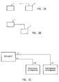
- Fig. 2A two classes of symbols 1 and 2 are shown.
- the class of symbols 1 is a rectangular shaped box whereas the class of symbols 2 is a rectangular shaped box with an upwards bended line, which in this example is hook-like.
- the class of symbols 1 represents kernel entity sets K i whereas the class of symbols 2 represents role entity sets P i .
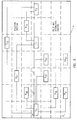
- a role entity set P i is a class of roles of entities e i comprised in a kernel entity set K i . This is symbolized in Fig. 2B where the role entity set P1 is a class of roles of entities e i comprised in the kernel entity set K1.
- FIG. 2C shows the example of Fig. 1 in the notation according to the invention.
- the entity sets "contract” and “description” are role entity sets of the kernel entity set "document”.
- the role entity sets "lease contract” and “sales contract” are assigned to the role entity set "contract”, thus specifying an even more restricted class of roles of entities e i comprised in the kernel entity set "document”.
- a further class of symbols 3 is shown as well as the class of symbols 1 representing a kernel entity set K i .
- the class of symbols 3 is a rectangular shaped box with another type of a downwards bended line, which in this example is shaped like a handle.
- This class of symbols 3 represents attributive entity sets A i .
- the attributive entity set 3 belongs to the kernel entity set 1 which is symbolized by the interconnection of the bended line of the class of symbols 3 with the rectangular shaped box of the class of symbols 1.
- Attributive entity sets A i are helpful to specify particular logical features of an entity set, such as a kernel entity set K i .
- the kernel entity set "document” has the attributive entity sets "processing information” and "preparation information”.
- the following rules apply:
- a further class of symbols 5 is shown by way of example.
- the class of symbols 5 is a rectangular shaped box with two hook-like downward bended lines.
- This class of symbols 5 represents relation entity sets R i .
- the relation entity set 5 defines a set of relations between the kernel entity sets 1 and 4.
- the class of symbols 5 comprises also a class of symbols 6 which is shown in Fig. 4C.
- This class of symbols 6 is to represent relation entity sets R i where the kernel entity sets K i in the definition D are not distinct. Therefore the two bended lines in this case point into the same direction as opposed to the case shown in Fig. 4B.
- the relation entity set 6 is assigned to the kernel entity set 1.
- the relation entity sets R i according to the invention are advantageously used in order to represent relations between kernel entity sets K i .
- the kernel entity sets "person” and "document” are shown.
- the relation entity set "person to person relation” is represented by a symbol 6 whereas the relation entity set "person to document relations” is represented by a symbol 5.
- the following additional rules are applied in the diagram shown in Fig. 4E:
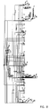
- Fig. 5 a more complex example of an entity relationship diagram according to the invention is shown.
- the entity relationship diagram is displayed on a display 9 of a computer system. It comprises the kernel entity sets K0, K1 and K2, the relation entity sets R00, R01, R02 and R12 as well as the attributive entity sets A00 and A01 and the role entity sets P00 and P01.
- the kernel entity sets are displayed along a horizontal line 7 which is indicated by the dashed line.
- the horizontal line 7 partitions the display into a first and a second section.
- the first section is the relation section where the relation entity sets are displayed and the second section is the kernel section where the kernel entity sets, and optionally the attributive entity sets and the role entity sets are displayed.
- the attributive entity sets and role entity sets of the kernel entity sets K1 and K2 of Fig. 5 are not shown in the diagram.
- the symbols representing the different entity sets are arranged in an array of allowable positions on the display 9. This array of allowable positions is indicated by the grid of lines shown in Fig. 5.
- the point 8 defines the origin of a coordinate system x, y of this array.
- the flow-chart shown in Fig. 6A illustrates the method for storing of the entity relationship diagram shown in Fig. 5 by way of example.
- the variables L, M and N are initialized to equal 0. These variables are indices of kernel entity sets K L , attributive entity sets A LU and role entity sets P LN , respectively.
- a first kernel entity set K0 is stored.
- the attributive entity sets A00 and A01 are stored in steps 603, 604 and 605.
- step 603 the attributive entity set A00 is stored.
- step 604 it is decided whether all attributive entity sets A 0M are already stored. Since in this case the decision is "no" the variable M is incremented in step 605 and the control returns to step 603 wherein the attributive entity set A01 is stored.
- step 606 the role entity set P00 is stored.
- step 607 is carried out where it is decided whether all role entity sets P 0N are already stored. Since in this case the decision is "no", the variable N is incremented in step 608, so that consequently in step 606 the role entity set P01 is stored.
- step 609 If the decision taken in step 607 is "yes”, it is decided in step 609 whether all kernel entity sets K L are already stored. If the decision is "no" the variable L is incremented in step 610 and the control returns back to step 602 so that a further kernel entity set K1 together with its attributive entity sets and role entity sets is input. This is repeated for all kernel entity sets which are to be stored.
- step 611 the relation entity sets R OP - in this case R00, R01, R02 and R12 - are stored.
- step 611 the kernel entity sets of the relation entity set which is to be stored are inputted. In this example only two kernel entity sets K O and K P are involved.
- step 612 the corresponding relation entity set R OP - such as the relation entity R01 - is stored.
- step 613 it is decided in step 613 whether all relation entity sets are already stored. If the decision is "no", the control returns back to step 611 so that the missing relation entity sets are stored subsequently. If the decision of step 613 is "yes" the flow of operations stops at step 614.
- the above described example, shown in Fig. 5, only comprises attributive and relative entity sets having a kernel entity set K L as mother entity set.
- the mother entity set of a role entity set may be a kernel entity set K L or another role entity set as it is shown in Fig. 2C.
- the mother entity set of an attributive entity set may be a kernel entity set K L or a role entity set.
- the role entity set P00 shown in Fig. 5, is the mother entity set of a further attributive entity set A P00 belonging to P00.
- the attributive entity set or sets belonging to the role entity set P LN are stored as well as the role entity set or sets having P LN as mother entity set. This procedure is repeated iteratively for these role entity set or sets, if there is a mother entity set to further role entity set or sets or to a further attributive entity set or sets among these role entity set or sets. It is to be noted that an attributive entity set may not be a mother entity set in order to avoid the introduction of redundance into the diagram.
- Fig. 6B shows a flow-chart which illustrates one way of carrying out the inventive method for displaying.
- the variables x, y, L, M and N are initialized to equal 0.
- step 621 it is decided whether all attributive entity sets A 0M are already displayed. Since the decision in this case is "no" the variable M is incremented in step 622, so that consequently in step 620 the attributive entity set A01 is displayed at the position (3,1).
- step 628 the relation entity sets R UP are displayed in the first section of the diagram.
- the flow of operations stops at step 629. It is to be noted, that in the more general case considered above the flow of operation illustrated with reference to Fig. 6B is modified correspondingly. In this case after step 623, the attributive and role entity sets of which P LN is the mother entity set are displayed.
- the order of kernel role or attributive entities in the horizontal or vertical direction is up to the specific problem area.
- One way of determining the order of kernel entity sets in the horizontal direction along the line 7 may be an alphabetical ordering according to the names of the kernel entity sets. The same could be done to determine the order of role entity sets having the same mother entity set in the vertical direction as well as to determine the order of attributive entity sets having the same mother entity set in the horizontal direction.
- a computer system such as a graphic tool, incorporating the teaching of the invention is also advantageous over the prior art, since the semantic information which is input by the user is checked automatically as to inconsistencies. If a user tries to input e. g. a relation entity set between two role entity sets this is recognized by the computer system as an invalid operation and the user is prompted to correct this operation. Thus no inconsistencies and redundant information is inputted.
- Fig. 7 shows an entity relationship diagram according to the prior art. This diagram is restructured according to the teaching of the invention. The result is shown in Fig. 8 which apparently shows the elimination of redundancy with respect to the prior art diagram.
- the entity relationship diagram of the invention may be transformed to an optimized database - such as a relational database. This transformation may be carried out by known methods.
- the resulting database may serve as a repository which is adapted to store instances of the entity sets of the diagram. Since the entity relationship diagram is redundancy free, the same applies as a consequence to the resulting data base. This also results in optimal access paths and a minimized access time to the instances stored in that database.
Landscapes
- Engineering & Computer Science (AREA)
- Databases & Information Systems (AREA)
- Theoretical Computer Science (AREA)
- Data Mining & Analysis (AREA)
- Physics & Mathematics (AREA)
- General Engineering & Computer Science (AREA)
- General Physics & Mathematics (AREA)
- Information Retrieval, Db Structures And Fs Structures Therefor (AREA)
- User Interface Of Digital Computer (AREA)
- Digital Computer Display Output (AREA)
- Stored Programmes (AREA)
Priority Applications (3)
| Application Number | Priority Date | Filing Date | Title |
|---|---|---|---|
| EP92116044A EP0589070A1 (fr) | 1992-09-19 | 1992-09-19 | Système d'ordinateur et procédé pour stocker et afficher un diagramme sémantique structuré entités relationelles |
| JP5225404A JP2554446B2 (ja) | 1992-09-19 | 1993-09-10 | 実体関連図を記憶及び表示するための方法並びにコンピュータ・システム |
| US08/123,391 US5386571A (en) | 1992-09-19 | 1993-09-17 | Computer system and method for storing and displaying of a semantically structured entity relationship diagram |
Applications Claiming Priority (1)
| Application Number | Priority Date | Filing Date | Title |
|---|---|---|---|
| EP92116044A EP0589070A1 (fr) | 1992-09-19 | 1992-09-19 | Système d'ordinateur et procédé pour stocker et afficher un diagramme sémantique structuré entités relationelles |
Publications (1)
| Publication Number | Publication Date |
|---|---|
| EP0589070A1 true EP0589070A1 (fr) | 1994-03-30 |
Family
ID=8210022
Family Applications (1)
| Application Number | Title | Priority Date | Filing Date |
|---|---|---|---|
| EP92116044A Withdrawn EP0589070A1 (fr) | 1992-09-19 | 1992-09-19 | Système d'ordinateur et procédé pour stocker et afficher un diagramme sémantique structuré entités relationelles |
Country Status (3)
| Country | Link |
|---|---|
| US (1) | US5386571A (fr) |
| EP (1) | EP0589070A1 (fr) |
| JP (1) | JP2554446B2 (fr) |
Cited By (7)
| Publication number | Priority date | Publication date | Assignee | Title |
|---|---|---|---|---|
| WO1996017311A1 (fr) * | 1994-11-29 | 1996-06-06 | St Computer Systems & Services Limited | Procede et structure pour grouper des tableaux de bases de donnees en classes et presenter chaque classe sous forme de modele entite-relation |
| WO1996017312A1 (fr) * | 1994-11-29 | 1996-06-06 | St Computer Systems & Services Limited | Logiciel de consultation individuelle |
| US5749079A (en) * | 1992-03-04 | 1998-05-05 | Singapore Computer Systems Limited | End user query facility including a query connectivity driver |
| GB2353613A (en) * | 1999-08-24 | 2001-02-28 | Quality Systems & Software Ltd | Information processor stores information objects and associated attributes |
| US8984006B2 (en) | 2011-11-08 | 2015-03-17 | Google Inc. | Systems and methods for identifying hierarchical relationships |
| US11341171B2 (en) * | 2011-06-03 | 2022-05-24 | Robert Mack | Method and apparatus for implementing a set of integrated data systems |
| US12524284B1 (en) * | 2023-02-23 | 2026-01-13 | Nvidia Corporation | Application programming interface to indicate kernel attributes |
Families Citing this family (9)
| Publication number | Priority date | Publication date | Assignee | Title |
|---|---|---|---|---|
| US5548699A (en) * | 1993-10-26 | 1996-08-20 | Fuji Xerox Co., Ltd. | Apparatus for presenting information according to evaluations of units of the information |
| US5933831A (en) * | 1998-01-09 | 1999-08-03 | Lsi Logic Corporation | Viewing entity relationship diagrams using hyperlinks |
| GB2343763B (en) * | 1998-09-04 | 2003-05-21 | Shell Services Internat Ltd | Data processing system |
| US6102927A (en) * | 1999-04-30 | 2000-08-15 | Wright; George A. | Blood lancet and method of manufacture |
| US6952741B1 (en) * | 1999-06-30 | 2005-10-04 | Computer Sciences Corporation | System and method for synchronizing copies of data in a computer system |
| US7693844B1 (en) * | 1999-10-29 | 2010-04-06 | Computer Sciences Corporation | Configuring processing relationships among entities of an organization |
| US7203925B1 (en) * | 2001-09-14 | 2007-04-10 | Emc Corporation | Graphical compiler |
| CA2429284A1 (fr) * | 2003-05-22 | 2004-11-22 | Cognos Incorporated | Regroupement visuel d'elements dans un diagramme |
| US20080098008A1 (en) * | 2006-10-19 | 2008-04-24 | Mustafa Eid | System and method for teaching entity-relationship modeling |
Family Cites Families (5)
| Publication number | Priority date | Publication date | Assignee | Title |
|---|---|---|---|---|
| US4479196A (en) * | 1982-11-15 | 1984-10-23 | At&T Bell Laboratories | Hyperedge entity-relationship data base systems |
| DE3714172A1 (de) * | 1986-04-28 | 1987-11-19 | Hitachi Ltd | Einrichtung zum durchsuchen von dokumenten in einem dokumentenablagesystem |
| US5175813A (en) * | 1989-08-14 | 1992-12-29 | International Business Machines Corporation | Window display system and method for creating multiple scrollable and non-scrollable display regions on a non-programmable computer terminal |
| JPH0378088A (ja) * | 1989-08-22 | 1991-04-03 | Mitsubishi Electric Corp | ネットワーク体系生成表示装置 |
| JPH05313846A (ja) * | 1992-05-08 | 1993-11-26 | Matsushita Electric Ind Co Ltd | ウインドウ制御装置 |
-
1992
- 1992-09-19 EP EP92116044A patent/EP0589070A1/fr not_active Withdrawn
-
1993
- 1993-09-10 JP JP5225404A patent/JP2554446B2/ja not_active Expired - Lifetime
- 1993-09-17 US US08/123,391 patent/US5386571A/en not_active Expired - Fee Related
Non-Patent Citations (3)
| Title |
|---|
| AFIPS CONFERENCE PROCEEDINGS vol. 56, 18 June 1987, CHICAGO, US pages 615 - 623 B. CZEJDO 'Graphical query languages for semantic database models' * |
| COMPUTER JOURNAL vol. 31, no. 3, June 1988, LONDON GB pages 258 - 268 K.S. DAWSON ET AL. 'From entity-relationship diagrams to fourth normal form: A pictorial aid to analysis' * |
| COMPUTER JOURNAL vol. 33, no. 1, February 1990, LONDON GB pages 31 - 39 M. AZMOODEH 'BRMQ: A database interface facility based on graph traversals and extended relationships on groups of entities' * |
Cited By (13)
| Publication number | Priority date | Publication date | Assignee | Title |
|---|---|---|---|---|
| US5701466A (en) * | 1992-03-04 | 1997-12-23 | Singapore Computer Systems Limited | Apparatus and method for end user queries |
| US5749079A (en) * | 1992-03-04 | 1998-05-05 | Singapore Computer Systems Limited | End user query facility including a query connectivity driver |
| US5809296A (en) * | 1994-11-29 | 1998-09-15 | St Computer Systems & Services Ltd. | Method and structure for clustering database tables into classes and presenting each class as an E-R model |
| GB2311636A (en) * | 1994-11-29 | 1997-10-01 | St Computer Systems & Services | Method and structure for clustering database tables into classes and presenting each class as an E-R model |
| GB2310061A (en) * | 1994-11-29 | 1997-08-13 | St Computer Systems & Services | End user query facility |
| WO1996017312A1 (fr) * | 1994-11-29 | 1996-06-06 | St Computer Systems & Services Limited | Logiciel de consultation individuelle |
| WO1996017311A1 (fr) * | 1994-11-29 | 1996-06-06 | St Computer Systems & Services Limited | Procede et structure pour grouper des tableaux de bases de donnees en classes et presenter chaque classe sous forme de modele entite-relation |
| GB2353613A (en) * | 1999-08-24 | 2001-02-28 | Quality Systems & Software Ltd | Information processor stores information objects and associated attributes |
| US11341171B2 (en) * | 2011-06-03 | 2022-05-24 | Robert Mack | Method and apparatus for implementing a set of integrated data systems |
| US11893046B2 (en) | 2011-06-03 | 2024-02-06 | Robert Mack | Method and apparatus for implementing a set of integrated data systems |
| US12566783B2 (en) | 2011-06-03 | 2026-03-03 | Robert Mack | Method and apparatus for implementing a set of integrated data systems |
| US8984006B2 (en) | 2011-11-08 | 2015-03-17 | Google Inc. | Systems and methods for identifying hierarchical relationships |
| US12524284B1 (en) * | 2023-02-23 | 2026-01-13 | Nvidia Corporation | Application programming interface to indicate kernel attributes |
Also Published As
| Publication number | Publication date |
|---|---|
| US5386571A (en) | 1995-01-31 |
| JPH07110761A (ja) | 1995-04-25 |
| JP2554446B2 (ja) | 1996-11-13 |
Similar Documents
| Publication | Publication Date | Title |
|---|---|---|
| US5386571A (en) | Computer system and method for storing and displaying of a semantically structured entity relationship diagram | |
| US6185476B1 (en) | Apparatus and method for managing and distributing design and manufacturing information throughout a sheet metal production facility | |
| EP0793831B1 (fr) | Methode et appareil pour base de donnees multidimensionnelle utilisant un code binaire hyperspatial | |
| EP0801773B1 (fr) | Organisation plane de stockage et systemes de stockage utilisant cette architecture | |
| US7197372B2 (en) | Apparatus and method for managing and distributing design and manufacturing information throughout a sheet metal production facility | |
| Chang et al. | A relational database system for images | |
| US6411862B1 (en) | Apparatus and method for managing and distributing design and manufacturing information throughout a sheet metal production facility | |
| González-Yuste et al. | Local refinement of 3-D triangulations using object-oriented methods | |
| US5720023A (en) | Appartus and method for storing diagram data | |
| Gotlieb et al. | Choosing a storage schema | |
| Krishnan et al. | Reusing mathematical models in ASCEND | |
| Nagy et al. | Approximation of polygonal maps by cellular maps | |
| Li et al. | Composite feature and variational design concepts in a feature-based design system | |
| Smith et al. | MDBS: A modeling and database system to support research in the earth sciences | |
| Jain | NSF workshop on visual information management systems: workshop report | |
| JP2992412B2 (ja) | Cad/cam装置におけるパラメータ設定方法 | |
| CA2185439C (fr) | Installation et procede permettant de stocker des donnees de diagramme | |
| Peskin et al. | Computational steering in a distributed computer based user | |
| Kela | Automatic finite element mesh generation and self-adaptive incremental analysis through geometric modeling | |
| Schmutz | The integrated data analysis and management system for pictorial applications | |
| Jakobovits et al. | A visual database environment for scientific research | |
| Düchting | A relational picture editor | |
| EP0466904A1 (fr) | Procede et appareil pour la gestion des informations dans une base de donnees informatisee | |
| Valle | Relational data handling techniques in integrated circuit mask layout procedures | |
| Bryce et al. | A Conceptual Basis for Graphics-Based Data Management |
Legal Events
| Date | Code | Title | Description |
|---|---|---|---|
| PUAI | Public reference made under article 153(3) epc to a published international application that has entered the european phase |
Free format text: ORIGINAL CODE: 0009012 |
|
| AK | Designated contracting states |
Kind code of ref document: A1 Designated state(s): DE FR GB |
|
| 17P | Request for examination filed |
Effective date: 19940718 |
|
| 18W | Application withdrawn |
Withdrawal date: 19960726 |