EP0589170A1 - Ferrure de tringle de commande pour fenêtres, portes et similaires - Google Patents
Ferrure de tringle de commande pour fenêtres, portes et similaires Download PDFInfo
- Publication number
- EP0589170A1 EP0589170A1 EP93111726A EP93111726A EP0589170A1 EP 0589170 A1 EP0589170 A1 EP 0589170A1 EP 93111726 A EP93111726 A EP 93111726A EP 93111726 A EP93111726 A EP 93111726A EP 0589170 A1 EP0589170 A1 EP 0589170A1
- Authority
- EP
- European Patent Office
- Prior art keywords
- faceplate
- pinion
- fitting according
- espagnolette fitting
- housing
- Prior art date
- Legal status (The legal status is an assumption and is not a legal conclusion. Google has not performed a legal analysis and makes no representation as to the accuracy of the status listed.)
- Granted
Links
- 239000004033 plastic Substances 0.000 claims abstract description 14
- 229920003023 plastic Polymers 0.000 claims abstract description 14
- 125000006850 spacer group Chemical group 0.000 claims abstract description 14
- 239000000463 material Substances 0.000 claims abstract description 10
- 238000001746 injection moulding Methods 0.000 claims abstract description 7
- 230000005540 biological transmission Effects 0.000 claims description 7
- 239000000314 lubricant Substances 0.000 claims 1
- 230000033001 locomotion Effects 0.000 description 12
- 239000000306 component Substances 0.000 description 10
- 238000004519 manufacturing process Methods 0.000 description 4
- 230000008901 benefit Effects 0.000 description 2
- 238000005520 cutting process Methods 0.000 description 2
- 239000002184 metal Substances 0.000 description 2
- 238000000034 method Methods 0.000 description 2
- 230000008569 process Effects 0.000 description 2
- 238000010079 rubber tapping Methods 0.000 description 2
- 239000004952 Polyamide Substances 0.000 description 1
- 230000009471 action Effects 0.000 description 1
- 230000000295 complement effect Effects 0.000 description 1
- 238000010276 construction Methods 0.000 description 1
- 239000008358 core component Substances 0.000 description 1
- 230000005489 elastic deformation Effects 0.000 description 1
- 238000002347 injection Methods 0.000 description 1
- 239000007924 injection Substances 0.000 description 1
- 238000009434 installation Methods 0.000 description 1
- 230000003993 interaction Effects 0.000 description 1
- 239000003879 lubricant additive Substances 0.000 description 1
- 230000007257 malfunction Effects 0.000 description 1
- 230000002093 peripheral effect Effects 0.000 description 1
- 229920002647 polyamide Polymers 0.000 description 1
- 229920006324 polyoxymethylene Polymers 0.000 description 1
- 239000012858 resilient material Substances 0.000 description 1
- 238000003892 spreading Methods 0.000 description 1
- 230000007480 spreading Effects 0.000 description 1
- 238000003860 storage Methods 0.000 description 1
Images


Classifications
-
- E—FIXED CONSTRUCTIONS
- E05—LOCKS; KEYS; WINDOW OR DOOR FITTINGS; SAFES
- E05C—BOLTS OR FASTENING DEVICES FOR WINGS, SPECIALLY FOR DOORS OR WINDOWS
- E05C9/00—Arrangements of simultaneously actuated bolts or other securing devices at well-separated positions on the same wing
- E05C9/04—Arrangements of simultaneously actuated bolts or other securing devices at well-separated positions on the same wing with two sliding bars moved in opposite directions when fastening or unfastening
- E05C9/041—Arrangements of simultaneously actuated bolts or other securing devices at well-separated positions on the same wing with two sliding bars moved in opposite directions when fastening or unfastening with rack and pinion mechanism
Definitions
- the invention relates to a connecting rod fitting for windows, doors or the like.
- a plug-in edge gear In such fittings, drive rods are guided longitudinally displaceably behind a faceplate covering the hardware groove, on which e.g. Locking pins or the like are attached, which penetrate the faceplate in longitudinal slots and can bring about locking with associated frame components.
- a rotary drive element - usually in the form of a pinion - is mounted, the teeth of which work together with openings in the drive rod.
- the rotary movement of an operating handle is converted into a translational movement of a drive rod.
- plug-in edge gears available in which a translational movement of different locking members, e.g. at the bottom and at the top of a window or door wing, in opposite directions.
- the plug-in edge gears are then equipped with thrust reversing gears, which have two drive rods, which can be set in opposite movement by the hand lever actuation.
- Insert edge gears of the specified type are known, for example, from DE-C-25 57 303 and EP-A-0 338 621.
- This design of the drive rods requires considerable manufacturing effort and can often only be obtained by attaching additional parts to the usual drive rods.
- EP-A-0 338 621 proposes a plug-in edge gear in which the reversing pinions of the thrust reversing gear are arranged on both sides of the drive member mounted in the gear housing.
- the bearing points for the two reversing pinions are each only half-shell-like in each of the two longitudinally symmetrical halves of the gear housing and this results in increased assembly effort with reduced storage stability, it is also disadvantageous that the thrust direction reversal is achieved in order to achieve this each of the two drive rods is in engagement with the two reversing pinions via two toothings and a further toothing on a drive rod is required for interaction with the rotary drive member.
- a plug-in edge gear has become known, which is a one-piece, e.g. has a gear housing made of a non-cutting stamped part.
- the attachment of the same to the faceplate is done by deforming, e.g. Riveting of material sections causes that protrudes from the gear housing and penetrate adapted openings in the faceplate.
- the gear housing only has an approximately semicircular bearing for the collars of the gearwheel serving as the drive member, because the latter cannot otherwise be inserted into the preformed housing.
- a plug-in edge gear in which an approximately bow-shaped housing is used for mounting the rotary drive member.
- the latter is placed between mutually parallel webs projecting from the back of the faceplate, which on the one hand serve to longitudinally guide the drive rod and on the other hand have segment-shaped recesses with which they support a part of the periphery of the bundle of the rotary drive member, in particular drive pinion.
- the connection of the bow-like housing with the webs of the faceplate requires an additional operation and accordingly requires a corresponding additional effort.
- DE-U-79 01 008 specifies a state of the art for the joint covering of the facing ends of faceplate rails, each of which is associated with connecting rod fittings to be installed adjacent to one another on a window or door leaf.
- An angled flap made of resilient material which is fastened on one faceplate, is used as the joint covering, and is pressed into its final position against the spring action when a fastening screw is screwed in through the faceplate.
- the disadvantage here is that the tab made of spring material must be attached to the faceplate by a separate operation.
- the locking plate according to EP-B-0 006 439 which is movably mounted on the faceplate.
- the aim of the invention is to provide a plug-in edge gear of the type mentioned, which avoids the aforementioned disadvantages of the prior art with the most cost-effective material selection and simple assembly. It is therefore proposed according to the invention a connecting rod fitting, which is characterized in that the housing of the transmission is made in one piece from plastic, in particular from plastic injection molding, and that on the faceplate with spacers projecting from the rear and at least one locking plate assigned to one end of the faceplate a subsequent faceplate end is made in one piece from plastic, in particular by injection molding, and that the locking plate is held in a hinged connection by a so-called film hinge material section with the faceplate.
- the gear housing has bores directed parallel to the bearing axis of the pinion serving as the drive member for receiving fastening screws for the bearing rosette of a pinion operating lever which have an angular, in particular hexagonal, cross section.
- the material displaced by self-tapping screws when cutting the thread can result as a result Avoid training in the polygon areas outside the screw diameter.
- the pinion used as the rotary drive member manages with a toothing which only extends over an angular arc of 90 °.
- the transmission housing closed in its rear, arcuate section, that is to say to provide it with a relatively thick wall, and thereby to achieve a considerable increase in the strength of the housing.
- a plug-in edge gear is equipped with a thrust reversing device, it is of great advantage if the reversing pinions are held in a stationary but rotatable manner by means of recesses made in the housing.
- the faceplate can then also have projections on its rear side, which are shaped such that they form a circular bearing each consisting of two bearing shells together with the recesses in the gear housing.
- the unit of faceplate, locking plate and spacer can be produced in one operation - by injection molding.
- a faceplate made of plastic can also be combined in this way, for example, with a locking plate made of metal.
- the gear housing has latching hooks which are assigned to one another in pairs on parallel walls. This ensures that the locking hooks hold the housing in connection with the faceplate without twisting.
- the locking edges of the locking hooks preferably point outwards. In this way it is achieved that, in the event of an uneven load on the gear serving as the rotary drive member, a tilting movement of the same and a resulting force component, which tries to push the housing apart, is used to help hold the gear housing on the faceplate.
- the transmission housing from a plastic which contains a lubricant additive.
- plastics not only have a high surface hardness, but are also characterized by good wear behavior.
- polyoximethylenes and polyamides can be used for this purpose.
- the spacers have locking projections on their longitudinal edges, which, together with the body of the spacer, penetrate an elongated hole in a drive rod and then lock behind it.
- the necessary elasticity for such a locking process is achieved by the material properties and the small wall thicknesses that result in the area of the through hole for the fastening screws.
- the diameter of this through-hole can preferably be selected such that any wall of the spacer that has collapsed inward is set back outward when the fastening screw is inserted into its original position.
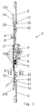
- a plug-in edge gear 1 can be seen, which has a gear housing 2, a drive pinion 3 and a faceplate 4.
- the rotary movement of a - not shown - operating hand lever is transmitted via a - also not shown - square mandrel.
- the rotation of the drive pinion 3 is then converted into a translational movement of a drive rod 5, which is guided in the gear housing 2 and on the faceplate 4.
- At least one locking pin 6 is attached to the drive rod 5, which in cooperation with a component attached to a frame ensures the locking of a window or door leaf in its closed position.
- a further drive rod 9 leads in the gear housing 2 and on the faceplate 4 and is intended to receive a thrust direction opposite to the drive rod 5.
- two pinions arranged next to one another are provided, which mesh with the respective toothed ends 8 of the drive rods 5 and 9, which are arranged diametrically opposite the center of the reversing pinion 7.
- connection of the gear housing 3 with the faceplate 4 is made via locking hooks 10, which penetrate the corresponding recesses 11 of the faceplate 4 and then snap into place on the outside thereof.
- the faceplate 4 is made in one piece and carries spacers 12 protruding from the rear for support on the base of a fitting groove provided in the sash profile. At least in the area of each spacer 12, fastening screws (not shown) for the plug-in edge gear 1 are also received in bores.
- the faceplate 4 is also formed in one piece with locking plates 14 and is connected to it by a section 15 which has a substantially smaller cross section than the faceplate 4 and the locking plate 14.
- the selection of the material and the cross section for the section 15 ensures that it is a so-called film hinge can be used.
- Each locking plate 14 is first raised into a position with the aid of the film hinge section 15 for the purpose of mounting an adjacent fitting component (not shown), as is indicated by dash-dotted lines in FIG. 1. Then the locking plate 14 is then pressed down to bridge the joint between adjacent fitting components on the front. This prevents the neighboring components from being lifted or bent out.
- Each locking plate 14 also has a spacer 16 on its underside, which is provided with a bore 17 for receiving a fastening screw (not shown). Furthermore, each locking plate 14 is also provided with a countersunk hole 17a for receiving a fastening screw, in such a way that it can expediently penetrate the adjacent fitting component and establish a linkage with it.
- a section of the plug-in edge gear 1 is shown on an enlarged scale.
- the polygonal passages 18 can be seen, into which self-tapping fastening screws can be screwed, which connect the bearing rosette of a hand lever (not shown) to the gear housing.
- the angle of rotation for the rotary drive element designed as drive pinion 3 and consequently also the angle of rotation for the hand lever are limited to 90 °.
- the section of the gearbox housing 2 in the form of a segment of a circle can be provided with a rear wall 19, which increases the overall stability and offers the toothless peripheral section of the drive pinion 3 an additional abutment.
- the plug-in edge gear 1 is equipped with a drive pinion 3 designed for a hand lever movement of 180 °, then the Rear wall 19 is eliminated.
- the drive pinion 3 is only supported via its side collars 20 which engage in corresponding recesses in the side walls of the transmission housing 2.
- FIG. 3 shows, as a special feature, the mounting of the two reversing pinions 7 in the transmission housing 2 and on the rear side of the faceplate 4 connected thereto.
- protrusions 21 protrude, which have arcuate bearing shells at their free ends.
- the reversing pinions 7 can each be supported here with their bearing journals.
- projections 21 are recesses 22 in the side walls of the gear housing 2, which form semicircular bearing shells, which lie opposite the bearing recesses in the end faces of the projections 21.
- the projections 21 and the recesses 22 each work together as a rotary bearing for the pins of the reversing pinion 7.
- FIG. 3 An advantageous embodiment for the plug-in edge gear 1 is achieved in that the latching hooks 10 connecting the gear housing 2 to the faceplate 4 have an arrangement distributed over the length of the gear housing 2 (FIG. 3) and in each case in pairs on the sides of the housing facing away from one another are formed (Fig. 4). A pair of such locking hooks 10 is also provided between the bearing points of both reversing pinions 7 so that the lifting forces occurring there can be safely absorbed between the gear housing 2 of the faceplate 4.
- Fig. 4 the connection of the gear housing 2 with the faceplate 4 is shown. It is clear that the locking hooks 10 integrally formed on the gear housing 2 penetrate the locking recesses 11 of the faceplate 4. Each latching hook 10 is provided with latching edges 23 projecting outwards, which engage a latching engagement 28 which lies on the outside of the faceplate 4 in its latching recesses 11.
- the latching hooks 10 are first displaced elastically inward by a sloping surface 24 leading their latching edges 23 into a recess 25 which is located in the side surfaces of a support web 29 for the drive rod 5.
- the latching hooks 10 When the latching hooks 10 penetrate further into the latching recesses 11, the latching hooks 10, with their inner edges assigned to their free end, meet inclined surfaces 30, which adjoin the recess 25 in the support web 29 towards the outside of the faceplate 4. As a result, an outward spreading movement is then forced onto each latching hook 10, so that its outwardly directed latching edge 23 positively engages behind the latching engagement 28 of the latching recess 11 in the faceplate 4.
- the contour of the recess 25 with the inclined surface 30 is chosen so that only elastic deformations of the latching hook 10 and the faceplate 4 are possible for producing the latching connection, but that a loosening of this latching connection is prevented without damaging the faceplate 4 or the gear housing 2.
- Fig. 5 shows a cross section through the spacer 12 with the bore 17a. It can be seen that the spacer 12 extends through the drive rod 9 in a slot 26 provided for this purpose. Lateral locking lugs 31 are attached to the spacer 12, the largest outside dimension 32 of which is larger than the inside dimension 33 of the elongated hole 26 of the drive rod 9.
- the locking lugs 31 are provided on their lower side with a bevel 34, which make it easier to clip in the drive rod 9. At their upper end, the latching lugs 31 have an almost horizontal section 35, the distance to the lower edge 36 of the connecting rod is selected so that the connecting rod 9 has sufficient space for its movement.
- the bore diameter 27 is selected such that the fastening screw 37 compensates for any plastic deformation that may be present, in that its outer contour 38 bears close to the inner diameter 39 of the bore 17a. This makes it impossible for the drive rod 9 to slide when the fastening screw 37 is installed.
Landscapes
- Engineering & Computer Science (AREA)
- Mechanical Engineering (AREA)
- General Details Of Gearings (AREA)
- Hinges (AREA)
- Housing For Livestock And Birds (AREA)
- Solid-Sorbent Or Filter-Aiding Compositions (AREA)
- Dry Formation Of Fiberboard And The Like (AREA)
- Slot Machines And Peripheral Devices (AREA)
Applications Claiming Priority (2)
| Application Number | Priority Date | Filing Date | Title |
|---|---|---|---|
| DE9212950U DE9212950U1 (de) | 1992-09-25 | 1992-09-25 | Treibstangenbeschlag für Fenster, Türen o.dgl. |
| DE9212950U | 1992-09-25 |
Publications (2)
| Publication Number | Publication Date |
|---|---|
| EP0589170A1 true EP0589170A1 (fr) | 1994-03-30 |
| EP0589170B1 EP0589170B1 (fr) | 1995-10-18 |
Family
ID=6884154
Family Applications (1)
| Application Number | Title | Priority Date | Filing Date |
|---|---|---|---|
| EP93111726A Expired - Lifetime EP0589170B1 (fr) | 1992-09-25 | 1993-07-22 | Ferrure de tringle de commande pour fenêtres, portes et similaires |
Country Status (4)
| Country | Link |
|---|---|
| EP (1) | EP0589170B1 (fr) |
| AT (1) | ATE129310T1 (fr) |
| DE (2) | DE9212950U1 (fr) |
| ES (1) | ES2080565T3 (fr) |
Cited By (8)
| Publication number | Priority date | Publication date | Assignee | Title |
|---|---|---|---|---|
| GB2281097A (en) * | 1993-08-19 | 1995-02-22 | Lb Plastics Ltd | A multi-point locking mechanism having locking members that move in opposite directions |
| US5722269A (en) * | 1992-12-22 | 1998-03-03 | Knurr-Mechanik Fur Die Elektronik Aktiengesellschaft | Locking device for cabinet or cupboard doors |
| FR2798949A1 (fr) * | 1999-09-28 | 2001-03-30 | Ferco Int Usine Ferrures | Menuiserie de type porte ou fenetre |
| EP1369547A1 (fr) * | 2002-06-05 | 2003-12-10 | MASTER S.r.l. | Dispositif d'actionnement, notamment pour utilisation avec poignées de fenêtre |
| DE102009000822A1 (de) * | 2009-02-12 | 2010-08-19 | Aug. Winkhaus Gmbh & Co. Kg | Antriebseinheit für einen Treibstangenbeschlag |
| GB2561141A (en) * | 2015-09-24 | 2018-10-10 | Assured Product Solutions Ltd | Window locking system |
| US20220049527A1 (en) * | 2019-02-18 | 2022-02-17 | Industrilås I Nässjö Ab | Rearrangable locking assembly for a door |
| WO2024245607A1 (fr) * | 2023-06-02 | 2024-12-05 | Maco Technologie Gmbh | Agencement d'ajustement pour un élément de levage et de coulissement ayant une liaison détachable entre un rail de couvercle et une boîte de vitesses |
Families Citing this family (12)
| Publication number | Priority date | Publication date | Assignee | Title |
|---|---|---|---|---|
| DE4403440C2 (de) * | 1994-02-04 | 1999-09-23 | Steinbach & Vollmann | Verschlußgehäuse |
| DE9403801U1 (de) * | 1994-03-07 | 1995-04-06 | Mayer & Co. Beschläge Ges.m.b.H., Salzburg | Beschlag für ein Fenster oder eine Tür |
| DE59610299D1 (de) * | 1996-01-20 | 2003-05-08 | Siegenia Aubi Kg | Betätigungsgetriebe für einen Treibstangenbeschlag |
| DE29601683U1 (de) * | 1996-02-02 | 1996-04-11 | Siegenia-Frank Kg, 57074 Siegen | Treibstangenbeschlag für ein Fenster, eine Tür o.dgl. |
| DE19737538C2 (de) * | 1997-08-28 | 2000-11-23 | Siegenia Frank Kg | Befestigungseinrichtung |
| DE19748202C2 (de) * | 1997-10-31 | 2002-09-26 | Roto Frank Ag | Getriebebeschlag für einen Flügelrahmen |
| DE19748059C2 (de) * | 1997-10-31 | 2001-11-29 | Weidtmann Wilhelm Kg | Treibstangenbeschlag für bewegliche Steuerelemente an einem Fenster oder einer Tür |
| FR2788550B1 (fr) * | 1999-01-18 | 2001-09-14 | Abs Rica Ateliers Bernard Seri | Cremone notamment avec pene demi-tour et indicateur d'etat |
| FR2789719B1 (fr) * | 1999-02-16 | 2001-05-18 | Ferco Int Usine Ferrures | Ferrure de verrouillage du type cremone ou analogue |
| DE10336149A1 (de) * | 2003-08-07 | 2005-03-03 | Aug. Winkhaus Gmbh & Co. Kg | Kantengetriebe |
| ES1256810Y (es) | 2020-07-30 | 2021-02-12 | Sist Tecnicos Del Accesorio Y Componentes S L | Dispositivo transmisor de movimiento bidireccional o monodireccional |
| GB2644426A (en) * | 2024-07-22 | 2026-04-15 | Assa Abloy Ltd | Improvements relating to door and window locking assemblies |
Citations (10)
| Publication number | Priority date | Publication date | Assignee | Title |
|---|---|---|---|---|
| DE6607469U (de) * | 1968-05-16 | 1971-03-18 | Frank Gmbh Wilh | Zapfengetriebe |
| FR2146079A5 (fr) * | 1971-07-15 | 1973-02-23 | Frank Gmbh Wilh | |
| DE2557303C2 (de) * | 1975-12-19 | 1978-03-23 | Siegenia-Frank Kg, 5900 Siegen- Kaan-Marienborn | Schubrichtungs-Umkehrgetriebe für Treibstangenbeschläge |
| DE7811092U1 (de) * | 1977-05-12 | 1978-08-10 | Ferco International, Usine De Ferrures De Batiment S.A.R.L., Reding-Annexepetit-Eich, Moselle (Frankreich) | Verschlussgetriebe, insbesondere stulpschienengetriebe fuer fenster, tueren o.dgl. |
| DE7901008U1 (de) * | 1979-01-16 | 1979-04-12 | Wilh. Frank Gmbh, 7022 Leinfelden- Echterdingen | Stosstellenueberdeckung fuer stulpschienen von treibstangenbeschlaegen fuer fenster, tueren o.dgl. |
| EP0006439A1 (fr) * | 1978-06-26 | 1980-01-09 | Siegenia-Frank Kg | Dispositif de chevauchement d'un joint entre deux têtières |
| EP0113664A2 (fr) * | 1983-01-07 | 1984-07-18 | Aug. Winkhaus GmbH & Co. KG | Dispositif de commande d'espagnolette |
| DE8701389U1 (de) * | 1987-01-29 | 1987-03-12 | Wilh. Frank Gmbh, 7022 Leinfelden-Echterdingen | Verstellgestänge |
| EP0338621A1 (fr) * | 1988-04-19 | 1989-10-25 | RUFFONI & ZOPPI S.R.L. | Crémone |
| EP0443177A2 (fr) * | 1990-02-19 | 1991-08-28 | Gretsch-Unitas GmbH Baubeschläge | Crémone pour ouvrant en profilés d'aluminium ou matière plastique |
-
1992
- 1992-09-25 DE DE9212950U patent/DE9212950U1/de not_active Expired - Lifetime
-
1993
- 1993-07-22 ES ES93111726T patent/ES2080565T3/es not_active Expired - Lifetime
- 1993-07-22 AT AT93111726T patent/ATE129310T1/de not_active IP Right Cessation
- 1993-07-22 EP EP93111726A patent/EP0589170B1/fr not_active Expired - Lifetime
- 1993-07-22 DE DE59300786T patent/DE59300786D1/de not_active Expired - Fee Related
Patent Citations (10)
| Publication number | Priority date | Publication date | Assignee | Title |
|---|---|---|---|---|
| DE6607469U (de) * | 1968-05-16 | 1971-03-18 | Frank Gmbh Wilh | Zapfengetriebe |
| FR2146079A5 (fr) * | 1971-07-15 | 1973-02-23 | Frank Gmbh Wilh | |
| DE2557303C2 (de) * | 1975-12-19 | 1978-03-23 | Siegenia-Frank Kg, 5900 Siegen- Kaan-Marienborn | Schubrichtungs-Umkehrgetriebe für Treibstangenbeschläge |
| DE7811092U1 (de) * | 1977-05-12 | 1978-08-10 | Ferco International, Usine De Ferrures De Batiment S.A.R.L., Reding-Annexepetit-Eich, Moselle (Frankreich) | Verschlussgetriebe, insbesondere stulpschienengetriebe fuer fenster, tueren o.dgl. |
| EP0006439A1 (fr) * | 1978-06-26 | 1980-01-09 | Siegenia-Frank Kg | Dispositif de chevauchement d'un joint entre deux têtières |
| DE7901008U1 (de) * | 1979-01-16 | 1979-04-12 | Wilh. Frank Gmbh, 7022 Leinfelden- Echterdingen | Stosstellenueberdeckung fuer stulpschienen von treibstangenbeschlaegen fuer fenster, tueren o.dgl. |
| EP0113664A2 (fr) * | 1983-01-07 | 1984-07-18 | Aug. Winkhaus GmbH & Co. KG | Dispositif de commande d'espagnolette |
| DE8701389U1 (de) * | 1987-01-29 | 1987-03-12 | Wilh. Frank Gmbh, 7022 Leinfelden-Echterdingen | Verstellgestänge |
| EP0338621A1 (fr) * | 1988-04-19 | 1989-10-25 | RUFFONI & ZOPPI S.R.L. | Crémone |
| EP0443177A2 (fr) * | 1990-02-19 | 1991-08-28 | Gretsch-Unitas GmbH Baubeschläge | Crémone pour ouvrant en profilés d'aluminium ou matière plastique |
Cited By (12)
| Publication number | Priority date | Publication date | Assignee | Title |
|---|---|---|---|---|
| US5722269A (en) * | 1992-12-22 | 1998-03-03 | Knurr-Mechanik Fur Die Elektronik Aktiengesellschaft | Locking device for cabinet or cupboard doors |
| GB2281097A (en) * | 1993-08-19 | 1995-02-22 | Lb Plastics Ltd | A multi-point locking mechanism having locking members that move in opposite directions |
| GB2281097B (en) * | 1993-08-19 | 1996-07-24 | Lb Plastics Ltd | Locking mechanisms |
| FR2798949A1 (fr) * | 1999-09-28 | 2001-03-30 | Ferco Int Usine Ferrures | Menuiserie de type porte ou fenetre |
| EP1088957A1 (fr) * | 1999-09-28 | 2001-04-04 | FERCO INTERNATIONAL Ferrures et Serrures de Bâtiment, Société Anonyme | Crémone pour menuiserie de type porte ou fenêtre |
| EP1369547A1 (fr) * | 2002-06-05 | 2003-12-10 | MASTER S.r.l. | Dispositif d'actionnement, notamment pour utilisation avec poignées de fenêtre |
| DE102009000822A1 (de) * | 2009-02-12 | 2010-08-19 | Aug. Winkhaus Gmbh & Co. Kg | Antriebseinheit für einen Treibstangenbeschlag |
| GB2561141A (en) * | 2015-09-24 | 2018-10-10 | Assured Product Solutions Ltd | Window locking system |
| GB2561141B (en) * | 2015-09-24 | 2021-03-03 | Assured Product Solutions Ltd | Window locking system |
| US20220049527A1 (en) * | 2019-02-18 | 2022-02-17 | Industrilås I Nässjö Ab | Rearrangable locking assembly for a door |
| US11946297B2 (en) * | 2019-02-18 | 2024-04-02 | Industrilås I Nässjö Aktiebolag | Rearrangable locking assembly for a door |
| WO2024245607A1 (fr) * | 2023-06-02 | 2024-12-05 | Maco Technologie Gmbh | Agencement d'ajustement pour un élément de levage et de coulissement ayant une liaison détachable entre un rail de couvercle et une boîte de vitesses |
Also Published As
| Publication number | Publication date |
|---|---|
| ES2080565T3 (es) | 1996-02-01 |
| EP0589170B1 (fr) | 1995-10-18 |
| DE9212950U1 (de) | 1992-12-03 |
| ATE129310T1 (de) | 1995-11-15 |
| DE59300786D1 (de) | 1995-11-23 |
Similar Documents
| Publication | Publication Date | Title |
|---|---|---|
| EP0589170B1 (fr) | Ferrure de tringle de commande pour fenêtres, portes et similaires | |
| DE3738300A1 (de) | Fenster, tuer od. dgl. bei dem bzw. der zumindest der fluegelrahmen aus metall- oder kunststoffprofilen zusammengesetzt ist | |
| EP0440986A2 (fr) | Crémone | |
| EP0440987B1 (fr) | Crémone | |
| DE3645256C2 (de) | Fenster- und Türbeschlag | |
| EP0763641B1 (fr) | Dispositif d'actionnement | |
| EP0534089B1 (fr) | Dispositif de commande pour les tiges coulissantes d'une serrure d'une fenêtre ou d'une porte | |
| EP1072745A1 (fr) | Ferrure de verrouillage pour fenêtres ou portes | |
| DE2115744A1 (de) | Kantengetriebe als Treibstangenbeschlag für Fenster, Türen od. dgl | |
| DE4402481C2 (de) | Stangenschloß | |
| EP1216335B1 (fr) | Engrenage intermediaire destine a des ferrures de portes et fenetres | |
| EP0899401B1 (fr) | Dispositif de fixation | |
| EP1264954B1 (fr) | Système de verouillage | |
| EP0431518A2 (fr) | Serrure pour meubles | |
| DE9001279U1 (de) | Treibstangengetriebe | |
| DE4409420A1 (de) | Betätigungsvorrichtung für Handhaben von Türen und Fenstern | |
| DE9114374U1 (de) | Treibstangenbeschlag für Fenster, Türen o.dgl. | |
| DE4040302C2 (de) | Betätigungsgetriebe für Fenster- und Türverschlüsse o. dgl. | |
| DE202007006223U1 (de) | Beschlag | |
| DE29703607U1 (de) | Betätigungshandhabe | |
| DE7811092U1 (de) | Verschlussgetriebe, insbesondere stulpschienengetriebe fuer fenster, tueren o.dgl. | |
| DE2461228A1 (de) | Verschlussvorrichtung fuer fenster, tueren oder dergleichen | |
| DE9420360U1 (de) | Stangenverschluß, insbesondere Stangenschloß für Möbel | |
| DE2334881A1 (de) | Verriegelungsvorrichtung fuer kippschwenkfluegel od. dgl. mit treibstangen, die ueber eckumlenkungen miteinander verbunden sind | |
| DE69319282T2 (de) | Schloss für Möbel oder dergleichen |
Legal Events
| Date | Code | Title | Description |
|---|---|---|---|
| PUAI | Public reference made under article 153(3) epc to a published international application that has entered the european phase |
Free format text: ORIGINAL CODE: 0009012 |
|
| AK | Designated contracting states |
Kind code of ref document: A1 Designated state(s): AT BE CH DE DK ES FR GB IT LI NL PT |
|
| 17P | Request for examination filed |
Effective date: 19940413 |
|
| 17Q | First examination report despatched |
Effective date: 19950406 |
|
| ITF | It: translation for a ep patent filed | ||
| GRAA | (expected) grant |
Free format text: ORIGINAL CODE: 0009210 |
|
| AK | Designated contracting states |
Kind code of ref document: B1 Designated state(s): AT BE CH DE DK ES FR GB IT LI NL PT |
|
| PG25 | Lapsed in a contracting state [announced via postgrant information from national office to epo] |
Ref country code: NL Free format text: LAPSE BECAUSE OF FAILURE TO SUBMIT A TRANSLATION OF THE DESCRIPTION OR TO PAY THE FEE WITHIN THE PRESCRIBED TIME-LIMIT Effective date: 19951018 Ref country code: DK Effective date: 19951018 |
|
| REF | Corresponds to: |
Ref document number: 129310 Country of ref document: AT Date of ref document: 19951115 Kind code of ref document: T |
|
| GBT | Gb: translation of ep patent filed (gb section 77(6)(a)/1977) |
Effective date: 19951024 |
|
| REF | Corresponds to: |
Ref document number: 59300786 Country of ref document: DE Date of ref document: 19951123 |
|
| PG25 | Lapsed in a contracting state [announced via postgrant information from national office to epo] |
Ref country code: PT Effective date: 19960118 |
|
| REG | Reference to a national code |
Ref country code: ES Ref legal event code: FG2A Ref document number: 2080565 Country of ref document: ES Kind code of ref document: T3 |
|
| ET | Fr: translation filed | ||
| NLV1 | Nl: lapsed or annulled due to failure to fulfill the requirements of art. 29p and 29m of the patents act | ||
| PLBE | No opposition filed within time limit |
Free format text: ORIGINAL CODE: 0009261 |
|
| STAA | Information on the status of an ep patent application or granted ep patent |
Free format text: STATUS: NO OPPOSITION FILED WITHIN TIME LIMIT |
|
| 26N | No opposition filed | ||
| PGFP | Annual fee paid to national office [announced via postgrant information from national office to epo] |
Ref country code: ES Payment date: 19990709 Year of fee payment: 7 |
|
| PGFP | Annual fee paid to national office [announced via postgrant information from national office to epo] |
Ref country code: BE Payment date: 19990727 Year of fee payment: 7 |
|
| PG25 | Lapsed in a contracting state [announced via postgrant information from national office to epo] |
Ref country code: ES Free format text: LAPSE BECAUSE OF NON-PAYMENT OF DUE FEES Effective date: 20000723 |
|
| PG25 | Lapsed in a contracting state [announced via postgrant information from national office to epo] |
Ref country code: BE Free format text: LAPSE BECAUSE OF NON-PAYMENT OF DUE FEES Effective date: 20000731 |
|
| BERE | Be: lapsed |
Owner name: SIEGENIA-FRANK K.G. Effective date: 20000731 |
|
| REG | Reference to a national code |
Ref country code: GB Ref legal event code: IF02 |
|
| PGFP | Annual fee paid to national office [announced via postgrant information from national office to epo] |
Ref country code: CH Payment date: 20030731 Year of fee payment: 11 |
|
| REG | Reference to a national code |
Ref country code: ES Ref legal event code: FD2A Effective date: 20010810 |
|
| PG25 | Lapsed in a contracting state [announced via postgrant information from national office to epo] |
Ref country code: LI Free format text: LAPSE BECAUSE OF NON-PAYMENT OF DUE FEES Effective date: 20040731 Ref country code: CH Free format text: LAPSE BECAUSE OF NON-PAYMENT OF DUE FEES Effective date: 20040731 |
|
| REG | Reference to a national code |
Ref country code: CH Ref legal event code: PL |
|
| PGFP | Annual fee paid to national office [announced via postgrant information from national office to epo] |
Ref country code: GB Payment date: 20060710 Year of fee payment: 14 |
|
| PGFP | Annual fee paid to national office [announced via postgrant information from national office to epo] |
Ref country code: FR Payment date: 20060720 Year of fee payment: 14 Ref country code: AT Payment date: 20060720 Year of fee payment: 14 |
|
| PGFP | Annual fee paid to national office [announced via postgrant information from national office to epo] |
Ref country code: IT Payment date: 20060731 Year of fee payment: 14 Ref country code: DE Payment date: 20060731 Year of fee payment: 14 |
|
| GBPC | Gb: european patent ceased through non-payment of renewal fee |
Effective date: 20070722 |
|
| PG25 | Lapsed in a contracting state [announced via postgrant information from national office to epo] |
Ref country code: DE Free format text: LAPSE BECAUSE OF NON-PAYMENT OF DUE FEES Effective date: 20080201 |
|
| PG25 | Lapsed in a contracting state [announced via postgrant information from national office to epo] |
Ref country code: GB Free format text: LAPSE BECAUSE OF NON-PAYMENT OF DUE FEES Effective date: 20070722 |
|
| REG | Reference to a national code |
Ref country code: FR Ref legal event code: ST Effective date: 20080331 |
|
| PG25 | Lapsed in a contracting state [announced via postgrant information from national office to epo] |
Ref country code: AT Free format text: LAPSE BECAUSE OF NON-PAYMENT OF DUE FEES Effective date: 20070722 |
|
| PG25 | Lapsed in a contracting state [announced via postgrant information from national office to epo] |
Ref country code: FR Free format text: LAPSE BECAUSE OF NON-PAYMENT OF DUE FEES Effective date: 20070731 |
|
| PG25 | Lapsed in a contracting state [announced via postgrant information from national office to epo] |
Ref country code: IT Free format text: LAPSE BECAUSE OF NON-PAYMENT OF DUE FEES Effective date: 20070722 |