EP0113664A2 - Dispositif de commande d'espagnolette - Google Patents
Dispositif de commande d'espagnolette Download PDFInfo
- Publication number
- EP0113664A2 EP0113664A2 EP84100081A EP84100081A EP0113664A2 EP 0113664 A2 EP0113664 A2 EP 0113664A2 EP 84100081 A EP84100081 A EP 84100081A EP 84100081 A EP84100081 A EP 84100081A EP 0113664 A2 EP0113664 A2 EP 0113664A2
- Authority
- EP
- European Patent Office
- Prior art keywords
- side walls
- faceplate
- edge
- gear
- groove step
- Prior art date
- Legal status (The legal status is an assumption and is not a legal conclusion. Google has not performed a legal analysis and makes no representation as to the accuracy of the status listed.)
- Granted
Links
- 230000005540 biological transmission Effects 0.000 claims description 6
- 230000008719 thickening Effects 0.000 claims description 5
- 238000009434 installation Methods 0.000 claims 2
- 230000035515 penetration Effects 0.000 abstract 1
- 239000000243 solution Substances 0.000 description 6
- 238000005452 bending Methods 0.000 description 3
- 238000005516 engineering process Methods 0.000 description 3
- 239000002184 metal Substances 0.000 description 3
- 238000004512 die casting Methods 0.000 description 2
- 239000000463 material Substances 0.000 description 2
- 238000004026 adhesive bonding Methods 0.000 description 1
- 230000002411 adverse Effects 0.000 description 1
- 230000000694 effects Effects 0.000 description 1
- 238000004519 manufacturing process Methods 0.000 description 1
- 230000003287 optical effect Effects 0.000 description 1
- 238000003825 pressing Methods 0.000 description 1
- 238000007493 shaping process Methods 0.000 description 1
- 238000003860 storage Methods 0.000 description 1
- 230000003313 weakening effect Effects 0.000 description 1
- 238000003466 welding Methods 0.000 description 1
Images

Classifications
-
- E—FIXED CONSTRUCTIONS
- E05—LOCKS; KEYS; WINDOW OR DOOR FITTINGS; SAFES
- E05C—BOLTS OR FASTENING DEVICES FOR WINGS, SPECIALLY FOR DOORS OR WINDOWS
- E05C9/00—Arrangements of simultaneously actuated bolts or other securing devices at well-separated positions on the same wing
- E05C9/02—Arrangements of simultaneously actuated bolts or other securing devices at well-separated positions on the same wing with one sliding bar for fastening when moved in one direction and unfastening when moved in opposite direction; with two sliding bars moved in the same direction when fastening or unfastening
- E05C9/021—Arrangements of simultaneously actuated bolts or other securing devices at well-separated positions on the same wing with one sliding bar for fastening when moved in one direction and unfastening when moved in opposite direction; with two sliding bars moved in the same direction when fastening or unfastening with rack and pinion mechanism
Definitions
- the recesses in the side walls are designed as pockets of shallow depth that are closed toward the outer sides of the side walls.
- the teeth of the faceplate are dimensioned accordingly.
- the invention has for its object to provide a storage of the edge gear unit, which allows a simplified shape of the side walls of the gear housing and at the same time a stable support of both the faceplate and the gear housing without significant bending moments in the side walls of the gear housing on the bottom surfaces of the outer , wider groove level allows.
- the measure of claim 2 ensures a play-free guidance of the drive rod in the gear housing; however, it is not absolutely necessary because basically the guidance of the drive rod in contact with the side of the faceplate facing it can also be transferred to the engagement with the pinion.
- the measure of claim 3 achieves the advantage of a particularly simple and inexpensive design of the side walls, irrespective of whether they are produced in sheet metal forming technology or in die casting technology.
- the bottom surface of the outer, wider groove step is visible through the teeth, but this visibility does not impair the appearance, because the tooth gaps can be relatively narrow, so that even a dirty floor of the outer, wider groove step Shadow of the teeth lies that it cannot be perceived.
- the visibility of the exposed teeth themselves does not adversely affect the functional optical appearance of the arrangement.
- the design according to claim 4 improves the appearance of the built-in edge gear unit to the highest standards, in that when the Flanges in the longitudinal center line of the faceplate the isolated edges of the side walls can be replaced by a continuous surface from side wall to side wall.
- the flanges stiffening a certain V ER- weakened by the perforations side walls arise, even if they do not collide.
- the measure of claim 5 which can be used together and without the measure of claim 4, brings a further improvement in appearance, in that the teeth of the faceplate and the tooth gaps can be completely laminated.
- a stiffening effect on the side walls can also emanate from the thickenings provided in claim 5.
- the measure of claim 7 is, if the recess, the narrower, inner N utha anacy anacyde bore is made in a side surface of the frame leg by a significant.
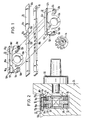
- the two side walls of the gear housing are designated 10 and.12.
- these two side walls are essentially C-shaped in design by means of three drills which cut the step groove; they include bearing eyes 10a and 12a for a gear pinion 14 and fastening projections 10b and 12b 'for the
- the fastening projections 10b and 12b are each designed with bores 10c and 12c for receiving the fastening screws.
- guide grooves 10d and 12d are provided which form a channel after the side walls 10 and 12 have been plugged together and which sandwiches a faceplate 16 and a drive rod 18.
- the guide grooves 10d and 12d are each defined by a flange 10e and 12e and a web 10f and 12f, the webs 10f and 12f holding the drive rod 18 in contact with the faceplate 16 and this in contact with the flanges 10e and 12e.
- openings 10g and 12g are provided at the bottom of the guide grooves 10d and 12d.
- teeth 16b are arranged on the faceplate 16 between tooth gaps 16a, namely on both edge surfaces 16c of the faceplate 16.
- These teeth 16b reach through the openings 10g and 12g, so that they rest on the bottom surfaces 20 of an outer, wider groove step 22 of the casement leg 24.
- the side walls 10 and 12 are provided with wedge-shaped thickenings 10h and 12h, which cover the teeth 16b and the tooth gaps 16a.
- the pinion 14 is in engagement with tooth engagement holes 18a of the drive rod 18 located in the area of the transmission.
- Teeth 16b corresponds to the original width of the faceplate 16.
- the inner, deeper groove step of the stepped groove 22 is designated by 26. It is followed by the recess 28 for receiving the gear housing.
- a twist grip unit 30 is usually attached to the casement.
- Figure 3 are analog parts with the same reference number chen denoted as in Figures 1 and 2, each increased by 100.
- the thickening of the side walls are omitted so that the teeth 116b and the tooth spaces 116a are exposed.
- analog parts are provided with the same reference numerals as in FIGS. 1 and 2, each increased by 200.
- the flanges are omitted.
- the faceplate is provided with recesses 416d on its underside and with recesses 416e on its edge surfaces 416c.
- the side walls 410 and 412 are made of sheet metal and are provided with multiple bends 410i and 412i 'such that they fill the recesses 416d and 416e and rest in the form of flanges 410e and 412e on the outside of the faceplate.
- the faceplate can be connected to the bends by spot welding, gluing or a clamp fit.
- the faceplate lies in the area of the recesses 416d by means of the angled side walls on the bottom surfaces 420 of the outer, wider groove step 422.
- the depth of the recesses 416e and 416d approximately corresponds to the thickness of the side walls 410 and 412, as indicated in FIGS. 6 and 7 by the dimension "d".
Landscapes
- Engineering & Computer Science (AREA)
- Mechanical Engineering (AREA)
- Gears, Cams (AREA)
- Refrigerator Housings (AREA)
- Lock And Its Accessories (AREA)
- Portable Nailing Machines And Staplers (AREA)
- Paper (AREA)
- Accommodation For Nursing Or Treatment Tables (AREA)
Priority Applications (1)
| Application Number | Priority Date | Filing Date | Title |
|---|---|---|---|
| AT84100081T ATE23206T1 (de) | 1983-01-07 | 1984-01-05 | Kantengetriebeeinheit. |
Applications Claiming Priority (2)
| Application Number | Priority Date | Filing Date | Title |
|---|---|---|---|
| DE3300423 | 1983-01-07 | ||
| DE19833300423 DE3300423A1 (de) | 1983-01-07 | 1983-01-07 | Kantengetriebeeinheit |
Publications (3)
| Publication Number | Publication Date |
|---|---|
| EP0113664A2 true EP0113664A2 (fr) | 1984-07-18 |
| EP0113664A3 EP0113664A3 (en) | 1985-06-19 |
| EP0113664B1 EP0113664B1 (fr) | 1986-10-29 |
Family
ID=6187885
Family Applications (1)
| Application Number | Title | Priority Date | Filing Date |
|---|---|---|---|
| EP84100081A Expired EP0113664B1 (fr) | 1983-01-07 | 1984-01-05 | Dispositif de commande d'espagnolette |
Country Status (3)
| Country | Link |
|---|---|
| EP (1) | EP0113664B1 (fr) |
| AT (1) | ATE23206T1 (fr) |
| DE (1) | DE3300423A1 (fr) |
Cited By (5)
| Publication number | Priority date | Publication date | Assignee | Title |
|---|---|---|---|---|
| GB2237601A (en) * | 1989-10-31 | 1991-05-08 | Mila Beslag As | Self-locking bolt drive mechanism |
| EP0440987A3 (en) * | 1990-02-05 | 1991-10-30 | Ferco International Usine De Ferrures De Batiment Societe A Responsabilite Limitee | Espagnolette fastening |
| EP0589170A1 (fr) * | 1992-09-25 | 1994-03-30 | Siegenia-Frank Kg | Ferrure de tringle de commande pour fenêtres, portes et similaires |
| EP0665353A1 (fr) * | 1994-01-28 | 1995-08-02 | Steinbach & Vollmann GmbH & Co. | Crémone |
| EP2218852A3 (fr) * | 2009-02-12 | 2011-09-14 | Aug. Winkhaus GmbH & Co. KG | Unité d'entraînement pour une ferrure de bielle |
Families Citing this family (5)
| Publication number | Priority date | Publication date | Assignee | Title |
|---|---|---|---|---|
| EP0261267B2 (fr) * | 1986-09-25 | 1999-12-15 | Dieter Ramsauer | Fermeture de barre pour portes d'armoires en tÔle |
| DE3672149D1 (de) * | 1986-09-25 | 1990-07-26 | Dieter Ramsauer | Stangenverschluss mit von der stange getragenen verriegelungszapfen, insbesondere doppelrollzapfen. |
| DE3710056C3 (de) * | 1987-03-27 | 1997-10-09 | Siegenia Frank Kg | Flügelrahmen für ein Fenster oder eine Tür, der aus Metall- oder Kunststoffprofilen zusammengesetzt ist |
| DE9001276U1 (de) * | 1990-02-05 | 1991-06-27 | Ferco International Usine de Ferrures de Bâtiment, Sarrebourg | Treibstangengetriebe |
| DE10336149A1 (de) * | 2003-08-07 | 2005-03-03 | Aug. Winkhaus Gmbh & Co. Kg | Kantengetriebe |
Family Cites Families (3)
| Publication number | Priority date | Publication date | Assignee | Title |
|---|---|---|---|---|
| DE2709213C2 (de) * | 1977-03-03 | 1984-02-02 | Wilh. Frank Gmbh, 7022 Leinfelden-Echterdingen | Kantengetriebe für ein Fenster, eine Tür o.dgl. |
| DE7905146U1 (de) * | 1979-02-23 | 1979-05-23 | Schaumburg-Lippische Baubeschlagfabrik W. Hautau Gmbh, 3061 Helpsen | Fluegelrahmen fuer fenster, tueren o.dgl. |
| GB2148377B (en) * | 1983-10-22 | 1987-02-18 | Hardware & Systems Patents Ltd | Improvements in fasteners for doors, windows and the like |
-
1983
- 1983-01-07 DE DE19833300423 patent/DE3300423A1/de not_active Withdrawn
-
1984
- 1984-01-05 AT AT84100081T patent/ATE23206T1/de not_active IP Right Cessation
- 1984-01-05 EP EP84100081A patent/EP0113664B1/fr not_active Expired
Cited By (6)
| Publication number | Priority date | Publication date | Assignee | Title |
|---|---|---|---|---|
| GB2237601A (en) * | 1989-10-31 | 1991-05-08 | Mila Beslag As | Self-locking bolt drive mechanism |
| GB2237601B (en) * | 1989-10-31 | 1994-01-05 | Mila Beslag As | A drive device for locking a window or door or the like |
| EP0440987A3 (en) * | 1990-02-05 | 1991-10-30 | Ferco International Usine De Ferrures De Batiment Societe A Responsabilite Limitee | Espagnolette fastening |
| EP0589170A1 (fr) * | 1992-09-25 | 1994-03-30 | Siegenia-Frank Kg | Ferrure de tringle de commande pour fenêtres, portes et similaires |
| EP0665353A1 (fr) * | 1994-01-28 | 1995-08-02 | Steinbach & Vollmann GmbH & Co. | Crémone |
| EP2218852A3 (fr) * | 2009-02-12 | 2011-09-14 | Aug. Winkhaus GmbH & Co. KG | Unité d'entraînement pour une ferrure de bielle |
Also Published As
| Publication number | Publication date |
|---|---|
| DE3300423A1 (de) | 1984-07-12 |
| EP0113664A3 (en) | 1985-06-19 |
| EP0113664B1 (fr) | 1986-10-29 |
| ATE23206T1 (de) | 1986-11-15 |
Similar Documents
| Publication | Publication Date | Title |
|---|---|---|
| WO2001092667A1 (fr) | Serrure a barres pour systeme de fermeture | |
| EP0113664B1 (fr) | Dispositif de commande d'espagnolette | |
| EP1803339B1 (fr) | Boitier ou unite de reception de type baie, a baguette de marquage | |
| DE2733772A1 (de) | Kreuzgelenk, insbesondere fuer lenkvorrichtungen von kraftfahrzeugen | |
| EP0228527A2 (fr) | Ferrure pour portes et fenêtres | |
| DE2623675C3 (de) | Wärmedämmendes Verbundprofil | |
| DE68907838T2 (de) | Eckverbinder. | |
| DE2709213C2 (de) | Kantengetriebe für ein Fenster, eine Tür o.dgl. | |
| DE2920320C2 (de) | Gehäuse | |
| DE2418674A1 (de) | Drehgriffgarnitur fuer tueren und fenster und verfahren zu ihrer herstellung | |
| DE2033042A1 (de) | Getriebe für Treibstangenbeschläge | |
| DE4321466C2 (de) | Zarge für ein Fenster | |
| DE7811092U1 (de) | Verschlussgetriebe, insbesondere stulpschienengetriebe fuer fenster, tueren o.dgl. | |
| DE2744052A1 (de) | Beschlag fuer tueren und waende aus glas | |
| DE3638407C2 (fr) | ||
| DE2417101C3 (de) | Kantenverschluß für Fenster, Türen o.dgl. | |
| DE19756391C1 (de) | Vorrichtung zum Fixieren einer Sprosse an einem durchgehenden Balken eines Hohlprofilrahmens | |
| DE9201532U1 (de) | Geradverbinder für hohle Abstandsprofile von Mehrscheibenisoliergläsern | |
| EP1532913A2 (fr) | Dispositif d'amortissement de sièges de toilettes et/ou de couvercle de toilettes | |
| DE20211901U1 (de) | Trennwand | |
| DE2703111B2 (de) | Rahmen für einen Fenster- oder Türflügel | |
| EP0359857A1 (fr) | Goupille de charnière | |
| DE7025066U (de) | Getriebe fuer treibstangenbeschlaege. | |
| CH631229A5 (de) | Getriebe fuer treibstangenbeschlag, tuer- oder fensterrahmen mit dem getriebe, verfahren zur herstellung des tuer- oder fensterrahmens und bohraggregat zur durchfuehrung des verfahrens. | |
| DE19839815A1 (de) | Federstift |
Legal Events
| Date | Code | Title | Description |
|---|---|---|---|
| PUAI | Public reference made under article 153(3) epc to a published international application that has entered the european phase |
Free format text: ORIGINAL CODE: 0009012 |
|
| AK | Designated contracting states |
Designated state(s): AT CH FR GB LI SE |
|
| PUAL | Search report despatched |
Free format text: ORIGINAL CODE: 0009013 |
|
| AK | Designated contracting states |
Designated state(s): AT CH FR GB LI SE |
|
| 17P | Request for examination filed |
Effective date: 19850823 |
|
| 17Q | First examination report despatched |
Effective date: 19860312 |
|
| RAP1 | Party data changed (applicant data changed or rights of an application transferred) |
Owner name: AUG. WINKHAUS GMBH & CO. KG |
|
| GRAA | (expected) grant |
Free format text: ORIGINAL CODE: 0009210 |
|
| AK | Designated contracting states |
Kind code of ref document: B1 Designated state(s): AT CH FR GB LI SE |
|
| REF | Corresponds to: |
Ref document number: 23206 Country of ref document: AT Date of ref document: 19861115 Kind code of ref document: T |
|
| ET | Fr: translation filed | ||
| PLBE | No opposition filed within time limit |
Free format text: ORIGINAL CODE: 0009261 |
|
| STAA | Information on the status of an ep patent application or granted ep patent |
Free format text: STATUS: NO OPPOSITION FILED WITHIN TIME LIMIT |
|
| 26N | No opposition filed | ||
| EAL | Se: european patent in force in sweden |
Ref document number: 84100081.3 |
|
| PGFP | Annual fee paid to national office [announced via postgrant information from national office to epo] |
Ref country code: SE Payment date: 19960111 Year of fee payment: 13 |
|
| PGFP | Annual fee paid to national office [announced via postgrant information from national office to epo] |
Ref country code: CH Payment date: 19960122 Year of fee payment: 13 |
|
| PG25 | Lapsed in a contracting state [announced via postgrant information from national office to epo] |
Ref country code: SE Effective date: 19970106 |
|
| PG25 | Lapsed in a contracting state [announced via postgrant information from national office to epo] |
Ref country code: LI Effective date: 19970131 Ref country code: CH Effective date: 19970131 |
|
| REG | Reference to a national code |
Ref country code: CH Ref legal event code: PL |
|
| EUG | Se: european patent has lapsed |
Ref document number: 84100081.3 |
|
| PGFP | Annual fee paid to national office [announced via postgrant information from national office to epo] |
Ref country code: GB Payment date: 20001227 Year of fee payment: 18 |
|
| REG | Reference to a national code |
Ref country code: GB Ref legal event code: IF02 |
|
| PG25 | Lapsed in a contracting state [announced via postgrant information from national office to epo] |
Ref country code: GB Free format text: LAPSE BECAUSE OF NON-PAYMENT OF DUE FEES Effective date: 20020105 |
|
| PGFP | Annual fee paid to national office [announced via postgrant information from national office to epo] |
Ref country code: AT Payment date: 20020124 Year of fee payment: 19 |
|
| PGFP | Annual fee paid to national office [announced via postgrant information from national office to epo] |
Ref country code: FR Payment date: 20020125 Year of fee payment: 19 |
|
| GBPC | Gb: european patent ceased through non-payment of renewal fee |
Effective date: 20020105 |
|
| PG25 | Lapsed in a contracting state [announced via postgrant information from national office to epo] |
Ref country code: AT Free format text: LAPSE BECAUSE OF NON-PAYMENT OF DUE FEES Effective date: 20030105 |
|
| PG25 | Lapsed in a contracting state [announced via postgrant information from national office to epo] |
Ref country code: FR Free format text: LAPSE BECAUSE OF NON-PAYMENT OF DUE FEES Effective date: 20030930 |
|
| REG | Reference to a national code |
Ref country code: FR Ref legal event code: ST |