EP0589580B1 - Procédé pour fabriquer un poissoir hydraulique à action directe - Google Patents
Procédé pour fabriquer un poissoir hydraulique à action directe Download PDFInfo
- Publication number
- EP0589580B1 EP0589580B1 EP93306957A EP93306957A EP0589580B1 EP 0589580 B1 EP0589580 B1 EP 0589580B1 EP 93306957 A EP93306957 A EP 93306957A EP 93306957 A EP93306957 A EP 93306957A EP 0589580 B1 EP0589580 B1 EP 0589580B1
- Authority
- EP
- European Patent Office
- Prior art keywords
- body member
- web
- mandrel
- hub
- predetermined shape
- Prior art date
- Legal status (The legal status is an assumption and is not a legal conclusion. Google has not performed a legal analysis and makes no representation as to the accuracy of the status listed.)
- Expired - Lifetime
Links
- 238000000034 method Methods 0.000 title claims description 51
- 238000004519 manufacturing process Methods 0.000 title claims description 6
- 238000003466 welding Methods 0.000 claims description 22
- 239000000463 material Substances 0.000 claims description 3
- IJGRMHOSHXDMSA-UHFFFAOYSA-N Atomic nitrogen Chemical compound N#N IJGRMHOSHXDMSA-UHFFFAOYSA-N 0.000 description 6
- 238000010438 heat treatment Methods 0.000 description 6
- OKTJSMMVPCPJKN-UHFFFAOYSA-N Carbon Chemical compound [C] OKTJSMMVPCPJKN-UHFFFAOYSA-N 0.000 description 3
- 229910052799 carbon Inorganic materials 0.000 description 3
- 229910052757 nitrogen Inorganic materials 0.000 description 3
- 238000005096 rolling process Methods 0.000 description 3
- 230000002411 adverse Effects 0.000 description 2
- 230000009286 beneficial effect Effects 0.000 description 2
- 238000004140 cleaning Methods 0.000 description 2
- 238000000354 decomposition reaction Methods 0.000 description 2
- 238000005242 forging Methods 0.000 description 2
- 239000002184 metal Substances 0.000 description 2
- 238000010791 quenching Methods 0.000 description 2
- 230000000171 quenching effect Effects 0.000 description 2
- CWYNVVGOOAEACU-UHFFFAOYSA-N Fe2+ Chemical compound [Fe+2] CWYNVVGOOAEACU-UHFFFAOYSA-N 0.000 description 1
- 229910000954 Medium-carbon steel Inorganic materials 0.000 description 1
- 229910000831 Steel Inorganic materials 0.000 description 1
- 230000004888 barrier function Effects 0.000 description 1
- 239000003990 capacitor Substances 0.000 description 1
- 238000005256 carbonitriding Methods 0.000 description 1
- 238000005255 carburizing Methods 0.000 description 1
- 230000000694 effects Effects 0.000 description 1
- 239000012530 fluid Substances 0.000 description 1
- 230000004807 localization Effects 0.000 description 1
- 229910000734 martensite Inorganic materials 0.000 description 1
- 230000000873 masking effect Effects 0.000 description 1
- 230000000149 penetrating effect Effects 0.000 description 1
- 238000007789 sealing Methods 0.000 description 1
- 239000010959 steel Substances 0.000 description 1
Images
Classifications
-
- B—PERFORMING OPERATIONS; TRANSPORTING
- B23—MACHINE TOOLS; METAL-WORKING NOT OTHERWISE PROVIDED FOR
- B23P—METAL-WORKING NOT OTHERWISE PROVIDED FOR; COMBINED OPERATIONS; UNIVERSAL MACHINE TOOLS
- B23P15/00—Making specific metal objects by operations not covered by a single other subclass or a group in this subclass
-
- F—MECHANICAL ENGINEERING; LIGHTING; HEATING; WEAPONS; BLASTING
- F01—MACHINES OR ENGINES IN GENERAL; ENGINE PLANTS IN GENERAL; STEAM ENGINES
- F01L—CYCLICALLY OPERATING VALVES FOR MACHINES OR ENGINES
- F01L1/00—Valve-gear or valve arrangements, e.g. lift-valve gear
- F01L1/20—Adjusting or compensating clearance
- F01L1/22—Adjusting or compensating clearance automatically, e.g. mechanically
- F01L1/24—Adjusting or compensating clearance automatically, e.g. mechanically by fluid means, e.g. hydraulically
- F01L1/245—Hydraulic tappets
- F01L1/25—Hydraulic tappets between cam and valve stem
-
- F—MECHANICAL ENGINEERING; LIGHTING; HEATING; WEAPONS; BLASTING
- F01—MACHINES OR ENGINES IN GENERAL; ENGINE PLANTS IN GENERAL; STEAM ENGINES
- F01L—CYCLICALLY OPERATING VALVES FOR MACHINES OR ENGINES
- F01L1/00—Valve-gear or valve arrangements, e.g. lift-valve gear
- F01L1/12—Transmitting gear between valve drive and valve
- F01L1/14—Tappets; Push rods
- F01L1/143—Tappets; Push rods for use with overhead camshafts
-
- Y—GENERAL TAGGING OF NEW TECHNOLOGICAL DEVELOPMENTS; GENERAL TAGGING OF CROSS-SECTIONAL TECHNOLOGIES SPANNING OVER SEVERAL SECTIONS OF THE IPC; TECHNICAL SUBJECTS COVERED BY FORMER USPC CROSS-REFERENCE ART COLLECTIONS [XRACs] AND DIGESTS
- Y10—TECHNICAL SUBJECTS COVERED BY FORMER USPC
- Y10T—TECHNICAL SUBJECTS COVERED BY FORMER US CLASSIFICATION
- Y10T29/00—Metal working
- Y10T29/49—Method of mechanical manufacture
- Y10T29/49229—Prime mover or fluid pump making
- Y10T29/49298—Poppet or I.C. engine valve or valve seat making
- Y10T29/49304—Valve tappet making
-
- Y—GENERAL TAGGING OF NEW TECHNOLOGICAL DEVELOPMENTS; GENERAL TAGGING OF CROSS-SECTIONAL TECHNOLOGIES SPANNING OVER SEVERAL SECTIONS OF THE IPC; TECHNICAL SUBJECTS COVERED BY FORMER USPC CROSS-REFERENCE ART COLLECTIONS [XRACs] AND DIGESTS
- Y10—TECHNICAL SUBJECTS COVERED BY FORMER USPC
- Y10T—TECHNICAL SUBJECTS COVERED BY FORMER US CLASSIFICATION
- Y10T29/00—Metal working
- Y10T29/49—Method of mechanical manufacture
- Y10T29/49229—Prime mover or fluid pump making
- Y10T29/49298—Poppet or I.C. engine valve or valve seat making
- Y10T29/49314—Poppet or I.C. engine valve or valve seat making with assembly or composite article making
-
- Y—GENERAL TAGGING OF NEW TECHNOLOGICAL DEVELOPMENTS; GENERAL TAGGING OF CROSS-SECTIONAL TECHNOLOGIES SPANNING OVER SEVERAL SECTIONS OF THE IPC; TECHNICAL SUBJECTS COVERED BY FORMER USPC CROSS-REFERENCE ART COLLECTIONS [XRACs] AND DIGESTS
- Y10—TECHNICAL SUBJECTS COVERED BY FORMER USPC
- Y10T—TECHNICAL SUBJECTS COVERED BY FORMER US CLASSIFICATION
- Y10T74/00—Machine element or mechanism
- Y10T74/21—Elements
- Y10T74/2101—Cams
- Y10T74/2107—Follower
Definitions
- the present invention relates generally to direct acting hydraulic tappets and specifically to a method for manufacturing such tappets. Such a method according to the preamble of claim 1 is described for example in JP-A-61055306.
- Welding is the most reliable means for forming this joint for structural rigidity considerations as well as for sealing; however, there are certain problems associated with the welding process and subsequent heat treating processes.
- heat treatments which include quenching of previously assembled parts can result in problems with distortion, higher scrap and re-work, cleaning and drag out of quenching fluids. As a result, additional operations may be required, thus increasing product cost.
- stopoff techniques prevent carbon and nitrogen from penetrating the surface of the part to permit conventional welding operations to be performed.
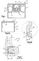
- a direct acting hydraulic tappet 10 comprising a cup-shaped body 12 , a web and hub element 14 , and a hydraulic assembly 16 .
- the hydraulic assembly per se is not part of the present invention, and typically comprises a plunger 18 in sliding engagement with the hub portion of the web and hub element, a piston 20 in sliding engagement with the plunger, and a check valve assembly 22 .
- the body 12 is formed of a hardenable alloyed steel such as SAE-5120 by a forging process which produces a very lightweight body having a thin wall section 24 and a relatively thicker top or cam face portion 26 .
- An oil groove 28 is formed by a rolling process as will be described in more detail below, which process also forms the interior of the body in a configuration which significantly enhances the weld joint between the web and hub assembly 14 and the body. Referring particularly to Fig.
- the surface designated 34 defines the interface between the web and hub 14 and the body, and it has been determined that an optimum weld joint can be obtained if the angle designated (a) of the interface is maintained at 44° ⁇ 2 degrees, the radius designated R1 is 12.7 mm (.5 in.) ⁇ 6.35 mm (.25 in.), and the radius designated R2 is 25.4 mm (1.0 in.) ⁇ 6.35 mm (.25 in.).
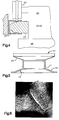
- Fig. 3 illustrates a prior art method for forming the oil groove 28 and the weld interface in the body 12 .
- a mandrel 34 is inserted into the body, and the body is located independently of the mandrel with the outer surface 42 of the body located in relation to a reference line 36 , after which a grooving tool 40 is forced into engagement with the body 12 while the body is rotated.
- the distance L between the cam face of the lifter body and the center of the oil groove is located off the outer surface of the cam face portion of the body while the inside contour, which is specifically adapted to define the weld interface described above, is determined by the shape of the mandrel, which locates off the inner surface of the cam face. Because there can be significant variation in the face thickness, this can produce inconsistencies in the groove and weld interface locations.
- the groove and weld interface characteristics are both located off the inner surface of the cam face. This is accomplished by means of rolling equipment 38 ' in which the mandrel 34 ' and the grooving tool 40 ' are mounted on a single slide 46 which is linearly movable in the direction of the double arrow relative to a base member 48 , and wherein the mandrel rotates about its longitudinal axis.
- the oil groove defined by the shape of the grooving tool and the weld interface defined by the mandrel are both located off the inner surface 44 of the body and will thus be consistent regardless of variations in cam face thickness.
- baffle 50 in the secondary oil reservoir 52 of the tappet so that oil drainage is inhibited when the engine is not running.
- Prior art baffle designs which are generally welded or otherwise fixed rigidly in place, can be relatively heavy, and do not extend to the full height of the secondary reservoir.
- the baffle 50 is very thin, preferably 0.25 mm ⁇ 0.025 mm and is press fit onto the hub portion 17 of the web and hub element 14 , to form an assembly designated 51 .
- the baffle 50 is initially only partially pressed onto the assembly 51 such that the height of the partially assembled web and hub and baffle assembly is greater than the distance between the weld interface against which the web is located and the inner surface 44 .
- the process of fixturing the assembly for welding will cause the baffle 50 to be positioned against the surface 44 of the body regardless of variations in location, thicknesses and tolerance stackups.
- an oil flowpath over the top of the baffle is defined by forming a depression 56 in the surface 44 , which depression can be formed during the body forging process and which is located so that it intersects the top surface of the baffle. The positioning of the baffle against the inner surface of the body and providing a flowpath above the baffle maximizes the volume of the secondary reservoir.
- the web and hub element 14 is preferably formed of a medium carbon steel such as SAE 1050 and the body only is heat treated prior to assembly. It is understood, however, that other heat treatable ferrous materials can be used.
- the heat treatment process per se is not part of the present invention; however, any well known surface hardening such as carbonitriding or carburizing can be used.
- the capacitive discharge (CD) welding process is tolerant of many hardening processes while maintaining weld integrity and this is a preferred method for fixing the web and hub element to the body.
- the assembly is placed in a suitable fixture and the area of the interface 34 of the web and hub with the body is subjected to a capacitive discharge (CD) welding process.
- CD capacitive discharge
- the welding energy is produced by a high speed, short duration electrical discharge of previously energized capacitors.
- the sudden discharge of energy liquifies the metal at the weld interface in a very localized area.
- the weld discharge time is typically less than 10 milliseconds; therefore, very little heating occurs outside the weld area.
- the heat treated areas outside the localized welding zone will not be adversely affected by the welding process.
- the heat affected zone, designated A, of the welded tappet assembly shows a fine, crystalline martensitic microstructure, which is necessary to obtain a high weld strength.
- the hydraulic assembly Upon completion of the body assembly, the hydraulic assembly is inserted into the web and hub assembly 14 to complete the hydraulic tappet assembly 10 as shown in Fig. 1 .
Landscapes
- Engineering & Computer Science (AREA)
- Mechanical Engineering (AREA)
- General Engineering & Computer Science (AREA)
- Valve-Gear Or Valve Arrangements (AREA)
Claims (5)
- Méthode de fabrication d'un poussoir hydraulique à action directe (10), comprenant les phases suivantes: la phase de réalisation d'un corps (12) généralement en forme de coupelle ; de réalisation d'une gorge circonférentielle (28) sur la paroi extérieure dudit corps, le procédé de réalisation de cette gorge déformant l'intérieur dudit corps pour obtenir une forme prédéterminée ; la phase de traitement thermique dudit corps ; la phase de mise en place d'un élément collerette-moyeu (14) contre ladite forme prédéterminée, le contour de la partie collerette dudit élément collerette-moyeu (14) et ladite forme prédéterminée définissant ensemble une interface de soudure ; enfin, la phase de soudage dudit élément collerette-moyeu (14) sur ledit corps (12) par un procédé de soudage localisé dans la zone de ladite interface ; méthode caractérisée par le fait
que ladite gorge (28) est formée par montage dudit corps (12) sur un mandrin tournant (34'), la face inférieure interne (44) dudit corps étant en butée contre l'extrémité du mandrin, ledit mandrin ayant un diamètre légèrement inférieur au diamètre intérieur du corps en forme de coupelle et une dépression correspondant à ladite forme prédéterminée et située à une distance prédéterminée de l'extrémité dudit mandrin (34'), et mettant en contact la paroi externe du corps (12) avec un outil à gorge (40') dont la position axiale par rapport au corps est également mesurée à partir de l'extrémité dudit mandrin (34'). - Méthode selon la revendication 1, caractérisée en ce
que ladite forme prédéterminée comprend une surface, formée sur la paroi interne du corps (12), qui définit un angle de 42 degrés à 46 degrés par rapport à une ligne parallèle à l'axe longitudinal dudit corps, ladite surface définissant ladite interface de soudure. - Méthode selon la revendication 2, caractérisée en ce
que ladite surface est limitée par un premier rayon (R1) de 6,35 mm à 19,05 mm convexe vers l'intérieur dudit corps et par un second rayon (R2) de 19,05 mm à 31,75 mm concave vers l'intérieur dudit corps. - Méthode selon la revendication 1, 2 ou 3, caractérisée en ce
que ledit procédé de soudage localisé est un procédé par décharge capacitive. - Méthode selon l'une quelconque des revendications 1 à 4, caractérisée par le fait
qu'elle comprend les phases de montage à la presse d'un élément chicane à paroi fine (50) sur la partie moyeu dudit élément collerette-moyeu (14) dans une position prédéterminée sur l'axe longitudinal de ladite partie moyeu avant la mise en place dudit élément collerette-moyeu contre ladite forme prédéterminée, ledit élément chicane étant repositionné sur ladite partie moyeu par ladite phase de positionnement afin de placer une extrémité dudit élément chicane contre la face inférieure interne (44) dudit corps (12).
Applications Claiming Priority (2)
| Application Number | Priority Date | Filing Date | Title |
|---|---|---|---|
| US07/950,534 US5280771A (en) | 1992-09-23 | 1992-09-23 | Direct acting hydraulic tappet |
| US950534 | 1992-09-23 |
Publications (2)
| Publication Number | Publication Date |
|---|---|
| EP0589580A1 EP0589580A1 (fr) | 1994-03-30 |
| EP0589580B1 true EP0589580B1 (fr) | 1997-03-12 |
Family
ID=25490555
Family Applications (1)
| Application Number | Title | Priority Date | Filing Date |
|---|---|---|---|
| EP93306957A Expired - Lifetime EP0589580B1 (fr) | 1992-09-23 | 1993-09-02 | Procédé pour fabriquer un poissoir hydraulique à action directe |
Country Status (5)
| Country | Link |
|---|---|
| US (2) | US5280771A (fr) |
| EP (1) | EP0589580B1 (fr) |
| KR (1) | KR100251516B1 (fr) |
| DE (1) | DE69308709T2 (fr) |
| MX (1) | MX9305867A (fr) |
Families Citing this family (23)
| Publication number | Priority date | Publication date | Assignee | Title |
|---|---|---|---|---|
| JPH05202706A (ja) * | 1992-01-29 | 1993-08-10 | Daido Steel Co Ltd | エンジンバルブおよびその製造方法 |
| JP3227634B2 (ja) * | 1994-11-16 | 2001-11-12 | フジオーゼックス株式会社 | 内燃機関用タペットおよびその製造方法 |
| JPH08226312A (ja) * | 1995-02-20 | 1996-09-03 | Fuji Oozx Inc | 弁隙間調節方法、並びにそれに用いるバルブリフタ及びその中間体 |
| DE19602012A1 (de) * | 1996-01-20 | 1997-07-24 | Schaeffler Waelzlager Kg | Durch einen Nocken einer Brennkraftmaschine betätigter Ventilstößel |
| US5729900A (en) * | 1996-05-06 | 1998-03-24 | Fuji Oozx, Inc. | Method of manufacturing a tappet in an internal combustion engine |
| US5642694A (en) * | 1996-05-24 | 1997-07-01 | General Motors Corporation | Integral formed oil column extender for hydraulic lash adjuster |
| JPH1077807A (ja) * | 1996-09-05 | 1998-03-24 | Fuji Oozx Inc | 内燃機関用タペットの製造方法 |
| US5839402A (en) * | 1997-07-29 | 1998-11-24 | Fuji Oozx Inc. | Wear resistant tappet |
| DE10106983A1 (de) * | 2001-02-15 | 2002-08-29 | Ina Schaeffler Kg | Stößel |
| US7128034B2 (en) | 2002-10-18 | 2006-10-31 | Maclean-Fogg Company | Valve lifter body |
| US7273026B2 (en) | 2002-10-18 | 2007-09-25 | Maclean-Fogg Company | Roller follower body |
| US7028654B2 (en) | 2002-10-18 | 2006-04-18 | The Maclean-Fogg Company | Metering socket |
| US7191745B2 (en) | 2002-10-18 | 2007-03-20 | Maclean-Fogg Company | Valve operating assembly |
| US6871622B2 (en) | 2002-10-18 | 2005-03-29 | Maclean-Fogg Company | Leakdown plunger |
| KR101119025B1 (ko) * | 2009-09-30 | 2012-03-13 | 윤동진 | 선박엔진 연료펌프용 태핏의 정밀 열간단조 방법 |
| CN103628941B (zh) * | 2012-08-24 | 2016-08-17 | 上海通用汽车有限公司 | 气门间隙自动调节的液压挺柱 |
| US10119607B2 (en) | 2016-04-15 | 2018-11-06 | Koyo Bearings North America Llc | Follower mechanism |
| DE102019120812A1 (de) | 2019-08-01 | 2021-02-04 | Schaeffler Technologies AG & Co. KG | Verfahren zum Herstellen einer Gewindemutter eines Gewindetriebes, insbesondere Kugelgewindemutter eines Kugelgewindetriebes |
| DE102019120813A1 (de) | 2019-08-01 | 2021-02-04 | Schaeffler Technologies AG & Co. KG | Verfahren zum Herstellen einer Gewindemutter eines Gewindetriebes, insbesondere Kugelgewindemutter eines Kugelgewindetriebes |
| US11149593B2 (en) | 2019-10-03 | 2021-10-19 | Koyo Bearings North America Llc | Tappet assembly with formed anti-rotation alignment device |
| US11143059B2 (en) | 2019-10-03 | 2021-10-12 | Koyo Bearings North America Llc | Tappet assembly with unground outer cup |
| US20230357285A1 (en) | 2020-08-20 | 2023-11-09 | Daicel Corporation | Silane coupling agent |
| CN117464314A (zh) * | 2023-10-17 | 2024-01-30 | 山西太钢不锈钢股份有限公司 | 一种高寿命节能型皮带运输机托辊用钢管的制造方法 |
Family Cites Families (15)
| Publication number | Priority date | Publication date | Assignee | Title |
|---|---|---|---|---|
| GB2014072B (en) * | 1978-01-31 | 1982-02-17 | British Steel Corp | Roll grooving tool for pipes |
| US4590898A (en) * | 1979-12-05 | 1986-05-27 | Eaton Corporation | Hydraulic tappet for direct-acting valve gear |
| DE3006644A1 (de) * | 1980-02-22 | 1981-09-03 | Motomak Motorenbau, Maschinen- u. Werkzeugfabrik, Konstruktionen GmbH, 8070 Ingolstadt | Ventilstoessel fuer brennkraftmaschinen mit obenliegender nockenwelle |
| DE3409236A1 (de) * | 1984-03-14 | 1985-09-19 | INA Wälzlager Schaeffler KG, 8522 Herzogenaurach | Aeusseres fuehrungsteil fuer einen ventilstoessel |
| DE3412153A1 (de) * | 1984-03-31 | 1985-10-10 | Motomak Motorenbau, Maschinen- u. Werkzeugfabrik, Konstruktionen GmbH, 8070 Ingolstadt | Verfahren zum befestigen eines trichterfoermigen fuehrungsteiles in der bohrungswand des tassenfoermigen gehaeuses eines sich selbsttaetig hydraulisch einstellenden ventilstoessels |
| JPS6155306A (ja) * | 1984-08-28 | 1986-03-19 | Riken Corp | 油圧タペツトの製造方法 |
| DE3434492A1 (de) * | 1984-09-20 | 1986-03-20 | Motomak Motorenbau, Maschinen- u. Werkzeugfabrik, Konstruktionen GmbH, 8070 Ingolstadt | Tassenfoermiges gehaeuse fuer einen mit einem sich selbsttaetig hydraulisch einstellenden spielausgleichselement versehenen ventilstoessel |
| DE3437478A1 (de) * | 1984-10-12 | 1986-04-17 | INA Wälzlager Schaeffler KG, 8522 Herzogenaurach | Sich selbsttaetig hydraulisch einstellender ventilstoessel |
| JPS61175204A (ja) * | 1985-01-30 | 1986-08-06 | Riken Corp | 油圧タペツトの製造方法 |
| DE3528432A1 (de) * | 1985-08-08 | 1987-02-19 | Motomak | Sich selbsttaetig hydraulisch einstellender ventilstoessel |
| DE3810436A1 (de) * | 1988-03-26 | 1989-10-12 | Schaeffler Waelzlager Kg | Sich selbsttaetig hydraulisch einstellender ventilstoessel |
| DE3828635A1 (de) * | 1988-08-24 | 1990-03-08 | Daimler Benz Ag | Verfahren zum herstellen von tassenstoesseln fuer hubkolbenmaschinen |
| DE8902780U1 (de) * | 1989-03-08 | 1989-04-20 | INA Wälzlager Schaeffler KG, 8522 Herzogenaurach | Sich selbsttätig hydraulisch einstellender Ventilstößel |
| DE4026793A1 (de) * | 1990-08-24 | 1992-03-05 | Freudenberg Carl Fa | Hydraulisches ventilspielausgleichselement fuer brennkraftmaschinen |
| DE4030987A1 (de) * | 1990-10-01 | 1992-04-02 | Schaeffler Waelzlager Kg | Sich selbsttaetig hydraulisch einstellender ventilstoessel |
-
1992
- 1992-09-23 US US07/950,534 patent/US5280771A/en not_active Expired - Fee Related
-
1993
- 1993-09-02 EP EP93306957A patent/EP0589580B1/fr not_active Expired - Lifetime
- 1993-09-02 DE DE69308709T patent/DE69308709T2/de not_active Expired - Fee Related
- 1993-09-17 KR KR1019930018822A patent/KR100251516B1/ko not_active Expired - Fee Related
- 1993-09-23 MX MX9305867A patent/MX9305867A/es not_active IP Right Cessation
- 1993-10-20 US US08/139,481 patent/US5430934A/en not_active Expired - Fee Related
Also Published As
| Publication number | Publication date |
|---|---|
| EP0589580A1 (fr) | 1994-03-30 |
| KR940006684A (ko) | 1994-04-25 |
| DE69308709T2 (de) | 1997-06-19 |
| US5430934A (en) | 1995-07-11 |
| DE69308709D1 (de) | 1997-04-17 |
| US5280771A (en) | 1994-01-25 |
| MX9305867A (es) | 1994-03-31 |
| KR100251516B1 (ko) | 2000-04-15 |
Similar Documents
| Publication | Publication Date | Title |
|---|---|---|
| EP0589580B1 (fr) | Procédé pour fabriquer un poissoir hydraulique à action directe | |
| EP0282166B1 (fr) | Arbres à cames assemblés. | |
| US5299881A (en) | Assembly of a cylindrical body made to finished dimensions | |
| US4087188A (en) | Pivot joint housing | |
| JPH0399741A (ja) | 弁の製造方法 | |
| US4983797A (en) | Method for manufacturing a composite camshaft | |
| US4993150A (en) | Process for producing cup tappets for reciprocating-piston machines | |
| US4945783A (en) | Ring gear with roll formed teeth | |
| US5280675A (en) | Camshaft and method of making a camshaft | |
| US5093209A (en) | Compound steel workpiece | |
| EP0302283B1 (fr) | Amortisseur de vibrations de torsion avec un carter déformé par rouleau | |
| GB2050207A (en) | Making camshafts | |
| US5737975A (en) | Built-up camshaft having induction-hardened cams and method of inductively hardening the cams | |
| US4270496A (en) | Welded article and method of making same | |
| US7020962B2 (en) | Method for producing a cam for a camshaft | |
| US5954020A (en) | Cup-shaped tappet | |
| KR20060128913A (ko) | 조립식 다중캠 | |
| CA1289776C (fr) | Arbre a cames et methode de fabrication connexe | |
| US4071933A (en) | Method of forming pivot joint housing | |
| US4122701A (en) | Collar sleeves and process and tool for the manufacture thereof | |
| EP3612345B1 (fr) | Procédé de formation d'un ensemble soudé et engrenage associé | |
| US6006429A (en) | Method of inductively hardening the cams of a camshaft | |
| US4095513A (en) | Piston with gudgeon pin and method of making same | |
| KR20080070004A (ko) | 냉매포함 중공 포펫 밸브 및 그 제조방법 | |
| US20050102834A1 (en) | Single piece cam method for the production thereof and assembly of a camshaft |
Legal Events
| Date | Code | Title | Description |
|---|---|---|---|
| PUAI | Public reference made under article 153(3) epc to a published international application that has entered the european phase |
Free format text: ORIGINAL CODE: 0009012 |
|
| AK | Designated contracting states |
Kind code of ref document: A1 Designated state(s): DE FR GB IT |
|
| 17P | Request for examination filed |
Effective date: 19940521 |
|
| 17Q | First examination report despatched |
Effective date: 19950622 |
|
| GRAG | Despatch of communication of intention to grant |
Free format text: ORIGINAL CODE: EPIDOS AGRA |
|
| GRAH | Despatch of communication of intention to grant a patent |
Free format text: ORIGINAL CODE: EPIDOS IGRA |
|
| GRAH | Despatch of communication of intention to grant a patent |
Free format text: ORIGINAL CODE: EPIDOS IGRA |
|
| GRAA | (expected) grant |
Free format text: ORIGINAL CODE: 0009210 |
|
| ITF | It: translation for a ep patent filed | ||
| AK | Designated contracting states |
Kind code of ref document: B1 Designated state(s): DE FR GB IT |
|
| REF | Corresponds to: |
Ref document number: 69308709 Country of ref document: DE Date of ref document: 19970417 |
|
| ET | Fr: translation filed | ||
| PLBE | No opposition filed within time limit |
Free format text: ORIGINAL CODE: 0009261 |
|
| STAA | Information on the status of an ep patent application or granted ep patent |
Free format text: STATUS: NO OPPOSITION FILED WITHIN TIME LIMIT |
|
| 26N | No opposition filed | ||
| PGFP | Annual fee paid to national office [announced via postgrant information from national office to epo] |
Ref country code: GB Payment date: 20000807 Year of fee payment: 8 |
|
| PGFP | Annual fee paid to national office [announced via postgrant information from national office to epo] |
Ref country code: FR Payment date: 20000905 Year of fee payment: 8 |
|
| PGFP | Annual fee paid to national office [announced via postgrant information from national office to epo] |
Ref country code: DE Payment date: 20000928 Year of fee payment: 8 |
|
| PG25 | Lapsed in a contracting state [announced via postgrant information from national office to epo] |
Ref country code: GB Free format text: LAPSE BECAUSE OF NON-PAYMENT OF DUE FEES Effective date: 20010902 |
|
| PG25 | Lapsed in a contracting state [announced via postgrant information from national office to epo] |
Ref country code: DE Free format text: LAPSE BECAUSE OF NON-PAYMENT OF DUE FEES Effective date: 20020501 |
|
| PG25 | Lapsed in a contracting state [announced via postgrant information from national office to epo] |
Ref country code: FR Free format text: LAPSE BECAUSE OF NON-PAYMENT OF DUE FEES Effective date: 20020531 |
|
| REG | Reference to a national code |
Ref country code: FR Ref legal event code: ST |
|
| PG25 | Lapsed in a contracting state [announced via postgrant information from national office to epo] |
Ref country code: IT Free format text: LAPSE BECAUSE OF NON-PAYMENT OF DUE FEES Effective date: 20050902 |