EP0589583A2 - Verfahren und Vorrichtung zur automatischen Ausfallbeseitigung eines Farbstrahldruckkopfes - Google Patents
Verfahren und Vorrichtung zur automatischen Ausfallbeseitigung eines Farbstrahldruckkopfes Download PDFInfo
- Publication number
- EP0589583A2 EP0589583A2 EP93306984A EP93306984A EP0589583A2 EP 0589583 A2 EP0589583 A2 EP 0589583A2 EP 93306984 A EP93306984 A EP 93306984A EP 93306984 A EP93306984 A EP 93306984A EP 0589583 A2 EP0589583 A2 EP 0589583A2
- Authority
- EP
- European Patent Office
- Prior art keywords
- ink
- printhead
- priming
- printheads
- plural
- Prior art date
- Legal status (The legal status is an assumption and is not a legal conclusion. Google has not performed a legal analysis and makes no representation as to the accuracy of the status listed.)
- Granted
Links
Images


Classifications
-
- B—PERFORMING OPERATIONS; TRANSPORTING
- B41—PRINTING; LINING MACHINES; TYPEWRITERS; STAMPS
- B41J—TYPEWRITERS; SELECTIVE PRINTING MECHANISMS, i.e. MECHANISMS PRINTING OTHERWISE THAN FROM A FORME; CORRECTION OF TYPOGRAPHICAL ERRORS
- B41J2/00—Typewriters or selective printing mechanisms characterised by the printing or marking process for which they are designed
- B41J2/005—Typewriters or selective printing mechanisms characterised by the printing or marking process for which they are designed characterised by bringing liquid or particles selectively into contact with a printing material
- B41J2/01—Ink jet
- B41J2/135—Nozzles
- B41J2/165—Prevention or detection of nozzle clogging, e.g. cleaning, capping or moistening for nozzles
- B41J2/16517—Cleaning of print head nozzles
- B41J2/1652—Cleaning of print head nozzles by driving a fluid through the nozzles to the outside thereof, e.g. by applying pressure to the inside or vacuum at the outside of the print head
- B41J2/16523—Waste ink transport from caps or spittoons, e.g. by suction
-
- B—PERFORMING OPERATIONS; TRANSPORTING
- B41—PRINTING; LINING MACHINES; TYPEWRITERS; STAMPS
- B41J—TYPEWRITERS; SELECTIVE PRINTING MECHANISMS, i.e. MECHANISMS PRINTING OTHERWISE THAN FROM A FORME; CORRECTION OF TYPOGRAPHICAL ERRORS
- B41J2/00—Typewriters or selective printing mechanisms characterised by the printing or marking process for which they are designed
- B41J2/005—Typewriters or selective printing mechanisms characterised by the printing or marking process for which they are designed characterised by bringing liquid or particles selectively into contact with a printing material
- B41J2/01—Ink jet
- B41J2/135—Nozzles
- B41J2/165—Prevention or detection of nozzle clogging, e.g. cleaning, capping or moistening for nozzles
- B41J2/16505—Caps, spittoons or covers for cleaning or preventing drying out
- B41J2/16508—Caps, spittoons or covers for cleaning or preventing drying out connected with the printer frame
Definitions
- the present invention relates generally to failure recovery methods for ink-jet printheads that automatically recovers multiple printheads from an ink-clogged condition. More particularly, the invention concerns such a method and system that include automatically capping and selectively priming a printhead to draw dried ink or other contaminant therefrom in response to a detected failure condition of the printhead.
- Ink-jet printhead nozzles commonly become plugged with wet or dry ink blobs or foreign matter, or become contaminated with internal bubbles that prevent them from operating properly. Lower print quality and user complaints often result. Even if the user discovers the problem, there often is nothing that can be done short of calling customer service. In a busy printer installation, such can be very costly, in lost opportunity due to excessive downtime, as well as in customer dissatisfaction.
- Drop detectors have been proposed that are capable of detecting the presence of an ink droplet fired from an ink-jet printhead and any delay associated with its firing.
- One such drop detector which is suitable for use with the invented automatic failure recovery method and system, is described in U.S. Patent No. 5,109,239 entitled “Inter Pen Offset Determination and Compensation in Multi-Pen Ink Jet Printing Systems", which issued April 28, 1992 and is subject to common ownership herewith.
- the drop detector described therein which preferably is optical, produces a drop present signal indicative of the presence of an ink droplet traversing a detection window within an ink-jet printer.
- the drop detector is described as being capable also of measuring the time between a firing pulse that heats a thin-film resistor to fire a drop of ink toward a print medium. From such detection and measurement techniques, a failure condition such as a clogged or partially clogged nozzle of an ink-jet printhead may be detected.
- a fully automatic failure recovery method and system are proposed that achieve selected priming and flushing of one of plural capped printheads in response to a detector that indicates the need therefor.
- the priming duration and pressure are adjustable in accordance with the automatically determined extent of the failure of the selected printhead reliably to fire ink droplets.
- the system uses a plural cam and cam follower subsystem that has few moving parts and that is selectively rotated via a one-way clutch with the ink-jet printer's paper feed drive motor.
- the recovery system cycle time is relatively short, thus minimizing printer downtime and maximizing quality print throughput.
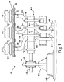
- Fig. 1 is a front elevational, cut-away, fragmentary view of the failure recovery system made in accordance with the preferred embodiment of the invention.
- Figs. 2A and 2B are a near side elevational, cut-away, fragmentary view of the system in various phases of its operation.
- Figs. 3A and 3B are a far side elevational, cut-away, fragmentary view of the system in various phases of its operation.
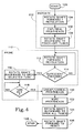
- Fig. 4 is a flowchart that illustrates the preferred method of the invention.
- Figs. 1, 2A, 2B, 3A and 3B collectively show the invented automatic ink-jet printhead failure system, in various cutaway, fragmentary elevations, generally at 10.
- system 10 includes plural ink-jet printheads such as printheads 12, 14, 16, there being sealingly associable with each a flexible vacuum tube such as tubes 18, 20, 22 operatively connecting the printheads with one or more ink accumulators such as accumulator 24.
- the printheads are sealingly associated with the flexible tubes via a sled assembly 26 that includes plural caps 28, 30, 32 covering upwardly extending peripheral bosses of associated cap mounts (not visible) mounted on a sled 34 having downwardly extending nozzles, 36, 38, 40 for connection with the upper ends of tubes 18, 20, 22.
- accumulator 24 includes three upwardly extending nozzles 42, 44, 46 to which tubes 18, 20, 22, respectively, are connected on their lower ends.
- sled assembly 26 provides for the sealing engagement of the printheads, while providing also for each of said printheads a through conduit extending from the upper reaches of the caps' lips to the lower reaches of the sled's nozzles.
- Such sled assembly 26 may be made in accordance with the teachings of my co-pending U.S. Patent Application Serial No. 07/935606 entitled “Ink-jet Printhead Cap Having Suspended Lip", which was filed 26/8/92 and which is commonly owned herewith (European Appln. No ). The disclosure of that co-pending patent application is incorporated herein by this reference.
- System 10 also includes a valve subsystem 48 that includes, for each of the tubes, a tube pinch-off mechanism such as mechanisms 50, 52, 54 capable of selectively substantially enabling the flow of ink from the printheads into one or more accumulators such as accumulator 24.
- a tube pinch-off mechanism such as mechanisms 50, 52, 54 capable of selectively substantially enabling the flow of ink from the printheads into one or more accumulators such as accumulator 24.
- system 10 includes a pump 56 operable with tubes 18, 20, 22 and one or more accumulators such as accumulator 24 to produce a vacuum in the tube corresponding with the selected printhead to draw ink therefrom.
- the pump cooperates with the valve subsystem such that, upon detection of the predefined failure condition of a selected printhead, the printhead is primed, thereby recovering the printer from the printhead's ink-clogging failure condition. It has been determined to be insufficient simply to draw ink from the printhead through the sled assembly into the tube through which the flow of ink has been enabled.
- pump 56 and valve subsystem 48 in accordance with the preferred embodiment of the invention are operable also to flush ink drawn into the tube from the selected printhead all the way through the tube and into one or more accumulators such as accumulator 24.
- this invented feature prevents the accumulation of ink, which typically would dry, in tubes 18, 20, 22 and thus greatly extends the time period over which system 10 is effective in unassisted failure recovery.
- pump 56 is of the conventional diaphragm-type and is operable to evacuate accumulator 24 by oscillatory motion, of a diaphragm 58, produced by an eccentric cam 60 mounted on the ink-jet printers' paper feed drive shaft 62, with a pivotal, chassis-mounted pump arm 64 acting as a cam follower. It will be appreciated that details of pump 56 are within the understanding of those skilled in the art. Importantly, however, pump 56 is operatively coupled with accumulator 24 (by a conduit not shown) and is capable of producing an approximately four pounds per square inch (4 psi) pressure differential at 14.7 psi ambient pressure.
- accumulator 24 has an approximately 150 cubic centimeter (150 cc) capacity, and is, as suggested by Figs. 1 through 3, formed as an integral part of the printer's chassis to which pump 56 is mounted.
- each of said pinch-off mechanisms such as pinch-off mechanism 48 includes a cam such as cam 66 fixedly mounted on a rotatable drive shaft 68, and an associated follower member such as member 70 configured to impinge on a corresponding tube such as tube 18.
- Member 70 preferably has segmented planar expanses 70 a , 70 b connected by an inverted U-shaped archway formed by laterally, upwardly extending spans 70 c , 70 d . Extending between and connecting spans 70 c , 70 d is a laterally extending pinch-off arm 70 e under which tube 18 is routed.
- plural follower members such as member 70 are molded integrally to extend forwardly in cantilever fashion from a horizontal support member 71 that forms a part of a preferably unitary frame member 71 and are made of a resilient polymer.
- Each follower member such as follower member 70 also has a terminal free end 70 f configured for following an associated cam such as cam 66 along its cam surface, which has a predefined profile substantially as shown in Figs. 2A and 2B.
- frame member 71 preferably is mounted for lateral movement relative to the cams such as cam 66 (e.g. on a movable carriage not shown), such that the follower members such as follower member 70 remain, while the printer is in operation, in idle positions between adjacent cams.
- the follower members are not always engaged with the cams, but rather are selectively engageable therewith only when the sled assembly and printhead carriage are in their service positions relative to the cams.
- Each cam such as cam 66 is selectively rotatable in the counterclockwise (CCW) direction shown in Figs. 2A, 2B, 3A and 3B (which will be referred to herein as backward) by a common drive motor that rotates the ink-jet printer's paper feed drive shaft 62.
- Interposing drive shaft 62 and drive shaft 68 is a one-way clutch 72 (refer to Fig. 1) coupling the drive motor with drive shaft 68 for the uni-directional (backward) rotation of the cams.
- valve subsystem 48 selective, backward rotation of the cams such as cam 66 with drive shaft 62 enables valve subsystem 48 to pinch off, thus to sealingly close, tubes 18, 20, 22 and yet selectively to enable the flow of ink through a selected one of them to prime and flush a selected printhead.
- clutch 72 is conventional, and may take the form of a wire-form slip clutch element (such as a wound spring which offers differential torque when coiled and uncoiled) as is known in the arts. From Figs. 3A and 3B, it may be seen that the tubes such as tubes 18, 20 are pinched off between pinch-off arms such as arms 70 e , 76 e and one or more upwardly extending bosses such as boss 73 formed in the printer's chassis.
- cam shaft 68 may, in an alternative but also preferred embodiment, be one and the same with drive shaft 62, with the cam collars shown in the drawings selectively rotating the cams thereabout when clutch 72 is engaged.
- the positional order (i.e. left to right in Fig. 1) of the various cams, e.g. illustrated cams 66, 74, 78, along shaft 68 is unimportant, as any order straightforwardly is accommodated to select a printhead for priming and flushing through an associated tube by the preferred method of the invention to be described by reference to Fig. 4.
- cam 74 having a predefined profile that is similar to that of cam 66 also is fixed on drive shaft 68 for rotation therewith. Importantly, cam 74 is different from cam 66 in the position around its periphery of what will be referred to herein as its notched step.
- Each of the cams (the number of which equals the number of printheads) within valve subsystem 48 is fixed in a predefined angular orientation about the axis of cam shaft 68 (or may be integrally molded with one another and therewith, within the spirit of the invention) with its tube-opening operative (notched) step disposed at radial angles thereabout which are separated by approximately 67°.
- notch immediately adjacent the step represents a closed condition of the associated tube, with a terminal end of a follower member, e.g. end 70 f of member 70, impinging therein to prevent even slight forward rotation of the cam (clockwise in Figs. 2A, 2B, 3A, 3B) that might inadvertently cause the closed tube to open).
- Each of the cams has a second, typically un-notched step that is aligned with every other such second step at what will be referred to herein as a start, or index, position.
- a start, or index, position One of the cams not shown will be understood to have only a single step that serves as both a start, or index, position of that cam and also a tube-opening operative step.
- each cam may have complementary, aligned notches in its periphery corresponding with the notched steps of each other cam, thereby to increase the robustness and security of a forward rotation-preventive mechanism to be described below.
- angularly positioned notched steps in cams such as cams 66, 74 provide the necessary phasing, or timing, relationship between the movement of corresponding follower members engaged therewith to provide for the independent, pinch-off control of each of tubes 18, 20, 22.
- Fig. 2A shows follower member 70 in a start position of non-impingement on tube 18 whereby ink may be drawn through tube 18 into accumulator 24 from printhead 12
- Fig. 3A shows a follower member 76 in a start position of non-impingement on tube 20 whereby ink may be drawn through tube 20 into accumulator 24 from printhead 14.
- Fig. 2A shows follower member 70 in a start position of non-impingement on tube 18 whereby ink may be drawn through tube 18 into accumulator 24 from printhead 12
- Fig. 3A shows a follower member 76 in a start position of non-impingement on tube 20 whereby ink may be drawn through tube 20 into accumulator 24 from printhead 14.
- each successive cam such as cam 78 (refer to Fig. 1) is fixed for rotation on shaft 68 at an identical predefined angle relative to cams 66, 74, but with its notched step located thereon at a clockwise angle relative to that of cam 74 of approximately 67°, in accordance with the preferred embodiment of the invention in which the total number of cams within valve subsystem 48 is four.
- cam 74 provides first for a fully opened condition (the un-notched step) of associated tube 20 (at 6 o'clock), then a gradually and fully closing condition (at approximately 11 o'clock) followed immediately by an abruptly fully opened condition (the notched step), then a gradually and fully closing condition that results in relatively long-term associated tube closure (from approximately 2 o'clock to 5:29 o'clock).
- the notch immediately adjacent the tube-opening operative step on each cam is for engaging a corresponding follower member such as member 70 to prevent forward rotation of drive shaft 68 that might result from a slight torque (associated, for example, with uncoiling the spring) developed by clutch 72 during forward rotation of drive shaft 62.
- a slight torque associated, for example, with uncoiling the spring
- the failure recovery method starts at 100.
- drive shaft 62 is rotated forward (in a clockwise direction opposite that indicated by the arrow in Figs. 2 and 3) one revolution.
- clutch 72 develops a slight torque in shaft 68 that causes rotation of the cams (into their start position shown in Figs.
- a carriage (not shown) mounting printheads 12, 14, 16 is moved into a service position to cap and seal the printheads against the lips of caps 28, 30, 32.
- frame 71 is moved into its operative, service position in which the follower members mounted thereon assume the positions shown in Figs. 1, 2A and 3A.
- drive shaft 62 and coupled cam shaft 68 are rotated backward to a pump position in which all tubes such as tubes 18, 20, 22 are pinched off or closed.
- this pump position of the cams is not shown in Figs. 2A, 2B, 3A or 3B, but represents aligned positions along the substantially circular arcs of the cams in which all follower members are forced downwardly to impinge on, thus to pinch-off, all associated tubes.
- the method includes priming a selected printhead to draw ink therefrom. Priming first involves rotating drive shaft 62 forward an integer number of revolutions at 112, 114 until it is determined, e.g. by a microprocessor controlling the rotation of the paper feed drive motor, that sufficient pressure differential (vacuum) has been developed via pump 56 to prime the printhead, based upon the extent of the clogging that has been detected.
- drive shaft 62 and shaft 68 are rotated backward at 116 a predetermined amount (corresponding to the angular orientation of the associated cam's operative, tube-opening (notched) step) to a position in which a selected tube is open.
- priming is terminated at 120 by uncapping, and thus unsealing, printheads 12, 14, 16.
- uncapping and unsealing the printheads causes the selected printhead, the associated tube of which is open, forcefully to eject wet and dry ink and other particulate through sled assembly 26 into the associated, open tube wherein the vacuum is sufficiently high, e.g. approximately 4 psi, to flush such ink and particulate entirely through the open tube and into one or more accumulators such as accumulator 24.
- all printheads conventionally are wiped at 122 and drive shaft 62 and coupled cam shaft 68 are rotated backward at 124 to open all tubes.
- drive shaft 62 is rotated at low torque forward to the mechanical stop to reset valve subsystem 48, thereby to stop the failure recovery cycle at 128.
- a single printhead or plural printheads mounted on a movable carriage after being primed as described above, preferably may be returned from the service position shown in Figs. 1 through 3B of capping and sealing engagement with sled assembly 26 to a printing position in which printing may resume.
- the entire failure recovery cycle time still is less than 20 seconds in duration.
- failure recovery requires no operator intervention.
- a printhead's failure condition is detected and automatically recovered from under the programmable control of a microprocessor that also typically would control also other printer operations.
- valve subsystem 48 is activated multiple times in some defined succession, first to unclog one printhead and then the other.
- both the pressure differential (vacuum) and duration or timing of the priming cycle are controllable by the microprocessor.
- the former is indicated at 112, 114 in Fig. 4 by the fact that the number of forward revolutions through which drive shaft 62 is driven to actuate pump 56 is programmable, thus establishing a pressure criterion which may be based upon the extent of a detected, defined failure condition of the printhead. For example, a slight clogging that is detected by the drop detector might require only 1 or 2 psi vacuum in the tube associated with the failed printhead, in which case no more time than is necessary in rotating drive shaft 62 and actuating pump 56 will be consumed in developing a vacuum in the associated tube.
- variable time-out at 118 that also is under microprocessor control.
- This programmable time-out can be relatively brief or extended, depending upon the microprocessor's determination of the time during which such determined vacuum need be applied to the printhead adequately to prime the printhead and flush its associated tube.
- the invented failure recovery system for ink-jet printers enables the selective priming of the printhead, followed by the flushing from the vicinity thereof, of ink and particulate that has been determined, e.g. by a drop detector, to be clogging the printhead's nozzles.
- the system and method that are described herein are fully automatic, requiring no operator intervention and taking the printer off-line, or into its service mode, for a relatively short period of time, e.g. less than twenty seconds.
- the printer is returned to service in a restored condition that extends its useful life and that ensures continued high print quality, yet without a field service or maintenance call.
- the invented method and system are implemented in relatively few, low-cost components that utilize the printer's existing drive motor to produce failure recovery that is reliable and cost effective.
Landscapes
- Engineering & Computer Science (AREA)
- Environmental & Geological Engineering (AREA)
- Ink Jet (AREA)
Applications Claiming Priority (2)
| Application Number | Priority Date | Filing Date | Title |
|---|---|---|---|
| US07/949,318 US5434605A (en) | 1992-09-21 | 1992-09-21 | Automatic failure recovery method and system for ink-jet printheads |
| US949318 | 1992-09-21 |
Publications (3)
| Publication Number | Publication Date |
|---|---|
| EP0589583A2 true EP0589583A2 (de) | 1994-03-30 |
| EP0589583A3 EP0589583A3 (en) | 1994-05-25 |
| EP0589583B1 EP0589583B1 (de) | 1998-01-07 |
Family
ID=25488907
Family Applications (1)
| Application Number | Title | Priority Date | Filing Date |
|---|---|---|---|
| EP93306984A Expired - Lifetime EP0589583B1 (de) | 1992-09-21 | 1993-09-03 | Verfahren und Vorrichtung zur automatischen Ausfallbeseitigung eines Farbstrahldruckkopfes |
Country Status (4)
| Country | Link |
|---|---|
| US (1) | US5434605A (de) |
| EP (1) | EP0589583B1 (de) |
| JP (1) | JP3366393B2 (de) |
| DE (1) | DE69316125T2 (de) |
Cited By (6)
| Publication number | Priority date | Publication date | Assignee | Title |
|---|---|---|---|---|
| EP0622201A3 (de) * | 1993-04-30 | 1994-12-21 | Hewlett Packard Co | Inbetriebstellungsgerät für einen Tintenstrahldrucker. |
| BE1008330A4 (fr) * | 1993-10-20 | 1996-04-02 | Lasermaster Corp | Systeme de recharge continue presentant une capacite d'encre predeterminee pour des cartouches d'encre a usage unique. |
| BE1008363A3 (fr) * | 1993-10-20 | 1996-04-02 | Lasermaster Corp | Systeme de recharge automatique pour des cartouches d'encre a usage unique. |
| EP0698495A3 (de) * | 1994-08-26 | 1997-12-10 | Canon Kabushiki Kaisha | Tintenstrahlaufzeichnungsvorrichtung und Rückgewinnungsverfahren dafür |
| EP1078764A3 (de) * | 1999-08-24 | 2001-06-20 | Canon Kabushiki Kaisha | Druckerzeugungsgerät, Drucker und Verfahren zur Druckersteuerung |
| EP1805030A4 (de) * | 2004-09-17 | 2009-03-25 | Fujifilm Dimatix Inc | Fluidhandhabung in tröpfchenaufzeichnungssystemen |
Families Citing this family (19)
| Publication number | Priority date | Publication date | Assignee | Title |
|---|---|---|---|---|
| EP0513833B1 (de) * | 1991-05-15 | 1996-09-25 | Seiko Epson Corporation | Tintenstrahlartiges Aufzeichnungsgerät und Reinigungsverfahren des Aufzeichnungskopfes |
| US5592034A (en) * | 1995-12-29 | 1997-01-07 | Pitney Bowes Inc. | Power shut down delay circuit for a postage meter mailing machine having an ink jet printer system |
| US6189995B1 (en) * | 1997-03-04 | 2001-02-20 | Hewlett-Packard Company | Manually replaceable printhead servicing module for each different inkjet printhead |
| US6039438A (en) * | 1997-10-21 | 2000-03-21 | Hewlett-Packard Company | Limiting propagation of thin film failures in an inkjet printhead |
| US6513902B1 (en) * | 1998-02-03 | 2003-02-04 | Fuji Photo Film Co., Ltd. | Apparatus for restoring ink jet recording head |
| JPH11268688A (ja) * | 1998-03-24 | 1999-10-05 | Showa Corp | 船外機のチルトシリンダ装置 |
| KR20000032753A (ko) * | 1998-11-17 | 2000-06-15 | 윤종용 | 프린터의 마이크로 인젝팅 디바이스 클리닝 방법 |
| US6132034A (en) * | 1999-08-30 | 2000-10-17 | Hewlett-Packard Company | Ink jet print head with flow control contour |
| US6347857B1 (en) | 1999-09-23 | 2002-02-19 | Encad, Inc. | Ink droplet analysis apparatus |
| JP2001162784A (ja) * | 1999-12-13 | 2001-06-19 | Canon Inc | インクジェット記録装置および記録方法 |
| US6398339B1 (en) * | 2000-06-16 | 2002-06-04 | Xerox Corp. | Time and drive systems for a multifunction ink jet printer maintenance station |
| US6938971B2 (en) * | 2001-06-21 | 2005-09-06 | Hewlett-Packard Development Company, L.P. | Method of servicing a pen when mounted in a printing device |
| JP2004299098A (ja) * | 2003-03-28 | 2004-10-28 | Brother Ind Ltd | インクジェットプリンタ |
| US20050276933A1 (en) * | 2004-06-14 | 2005-12-15 | Ravi Prasad | Method to form a conductive structure |
| JP4629465B2 (ja) * | 2005-03-11 | 2011-02-09 | 株式会社日立産機システム | インクジェット記録装置 |
| JP2007301991A (ja) * | 2006-04-14 | 2007-11-22 | Seiko Epson Corp | 液体噴射ヘッド用のメンテナンス装置及び液体噴射装置 |
| US7992960B2 (en) | 2007-01-31 | 2011-08-09 | Hewlett-Packard Development Company, L.P. | Non-user-initiated preventative maintenace modes for inkjet-printing device |
| US8262187B2 (en) * | 2007-11-27 | 2012-09-11 | Xerox Corporation | Off-line printhead inspection and recovery unit for production piezo ink jet architectures |
| CN104339871B (zh) * | 2013-07-30 | 2017-01-18 | 京瓷办公信息系统株式会社 | 流路开关装置以及具备该流路开关装置的喷墨记录装置 |
Family Cites Families (10)
| Publication number | Priority date | Publication date | Assignee | Title |
|---|---|---|---|---|
| US4493993A (en) * | 1982-11-22 | 1985-01-15 | Sperry Corporation | Apparatus for optically detecting ink droplets |
| DE3611333A1 (de) * | 1985-04-05 | 1986-10-16 | Canon K.K., Tokio/Tokyo | Fluessigkeitsstrahl-aufzeichnungsgeraet und in dem geraet verwendete saug-regeneriereinrichtung |
| JPS62292438A (ja) * | 1986-06-13 | 1987-12-19 | Canon Inc | インクジエツト記録装置 |
| US4853717A (en) * | 1987-10-23 | 1989-08-01 | Hewlett-Packard Company | Service station for ink-jet printer |
| JP2527774B2 (ja) * | 1987-12-29 | 1996-08-28 | キヤノン株式会社 | インクジェット記録装置 |
| US5018884A (en) * | 1988-03-02 | 1991-05-28 | Canon Kabushiki Kaisha | Recording apparatus in which a plurality of carriages can be connected and separated |
| JPH02184453A (ja) * | 1989-01-11 | 1990-07-18 | Canon Inc | インクジェット記録装置 |
| EP0785075B1 (de) * | 1989-10-22 | 2001-01-10 | Canon Kabushiki Kaisha | Rückgewinnungsvorrichtung mit einer Schlauchpumpe |
| EP0447262A1 (de) * | 1990-03-16 | 1991-09-18 | Canon Kabushiki Kaisha | Faksimilegerät |
| US5103244A (en) * | 1990-07-05 | 1992-04-07 | Hewlett-Packard Company | Method and apparatus for cleaning ink-jet printheads |
-
1992
- 1992-09-21 US US07/949,318 patent/US5434605A/en not_active Expired - Fee Related
-
1993
- 1993-09-03 DE DE69316125T patent/DE69316125T2/de not_active Expired - Fee Related
- 1993-09-03 EP EP93306984A patent/EP0589583B1/de not_active Expired - Lifetime
- 1993-09-21 JP JP23467393A patent/JP3366393B2/ja not_active Expired - Fee Related
Cited By (9)
| Publication number | Priority date | Publication date | Assignee | Title |
|---|---|---|---|---|
| EP0622201A3 (de) * | 1993-04-30 | 1994-12-21 | Hewlett Packard Co | Inbetriebstellungsgerät für einen Tintenstrahldrucker. |
| BE1008330A4 (fr) * | 1993-10-20 | 1996-04-02 | Lasermaster Corp | Systeme de recharge continue presentant une capacite d'encre predeterminee pour des cartouches d'encre a usage unique. |
| BE1008363A3 (fr) * | 1993-10-20 | 1996-04-02 | Lasermaster Corp | Systeme de recharge automatique pour des cartouches d'encre a usage unique. |
| EP0698495A3 (de) * | 1994-08-26 | 1997-12-10 | Canon Kabushiki Kaisha | Tintenstrahlaufzeichnungsvorrichtung und Rückgewinnungsverfahren dafür |
| US5805180A (en) * | 1994-08-26 | 1998-09-08 | Canon Kabushiki Kaisha | Ink jet recording apparatus which performs suction recovery with a cap and method for same |
| US6340217B1 (en) | 1994-08-26 | 2002-01-22 | Canon Kabushiki Kaisha | Ink jet recording apparatus and recovery method thereof |
| EP1078764A3 (de) * | 1999-08-24 | 2001-06-20 | Canon Kabushiki Kaisha | Druckerzeugungsgerät, Drucker und Verfahren zur Druckersteuerung |
| US6612682B1 (en) | 1999-08-24 | 2003-09-02 | Canon Kabushiki Kaisha | Pressure generating apparatus, printing apparatus, and method for controlling printing apparatus |
| EP1805030A4 (de) * | 2004-09-17 | 2009-03-25 | Fujifilm Dimatix Inc | Fluidhandhabung in tröpfchenaufzeichnungssystemen |
Also Published As
| Publication number | Publication date |
|---|---|
| EP0589583A3 (en) | 1994-05-25 |
| DE69316125T2 (de) | 1998-04-16 |
| JP3366393B2 (ja) | 2003-01-14 |
| DE69316125D1 (de) | 1998-02-12 |
| JPH06210876A (ja) | 1994-08-02 |
| EP0589583B1 (de) | 1998-01-07 |
| US5434605A (en) | 1995-07-18 |
Similar Documents
| Publication | Publication Date | Title |
|---|---|---|
| US5434605A (en) | Automatic failure recovery method and system for ink-jet printheads | |
| EP0635371B1 (de) | Ansaugsystem und ansaugleitungsfreie Kappe für Tintenstrahldrucker | |
| EP0313204B1 (de) | Instandsetzungsstelle für Farbstrahldrucker | |
| JP2879608B2 (ja) | メンテナンスステーションおよびその駆動方法 | |
| US6916080B2 (en) | Cleaning device for cleaning printhead of ink-jet printer | |
| US5614929A (en) | Manual pen selection for clearing nozzles without removal from pen carriage | |
| US8529028B2 (en) | Fluid distribution system having printhead bypass from container | |
| EP0630754B1 (de) | Tintenstrahlaufzeichnungsgerät | |
| EP0273362B1 (de) | Tintenstrahlaufzeichnungsgerät | |
| US6513904B1 (en) | Method for servicing an inkjet printhead | |
| US6953243B2 (en) | Liquid ejecting head unit and manufacturing method therefor | |
| US6419343B1 (en) | Printer and method for priming an inkjet printhead | |
| US6554394B1 (en) | Carriage, liquid ejection head, printer, head inserting method and head positioning method | |
| JPH0521745B2 (de) | ||
| JPH1067121A (ja) | インクジェット方式の画像形成装置 | |
| JP3492078B2 (ja) | インクジェット記録装置 | |
| JP2528635B2 (ja) | インクジェット装置 | |
| WO2013106089A1 (en) | Reciprocating carriage printer with air bubble dislodging and removal | |
| JPS6013556A (ja) | インクジエツト記録装置 | |
| JP2538205B2 (ja) | インクジェット記録装置 | |
| US20090153600A1 (en) | System and method for detecting fluid ejection volume | |
| JPH07205452A (ja) | インクジェット装置 | |
| JPH06191053A (ja) | インクジェット記録装置 | |
| JP2003205634A (ja) | 画像形成装置 |
Legal Events
| Date | Code | Title | Description |
|---|---|---|---|
| PUAI | Public reference made under article 153(3) epc to a published international application that has entered the european phase |
Free format text: ORIGINAL CODE: 0009012 |
|
| AK | Designated contracting states |
Kind code of ref document: A2 Designated state(s): DE FR GB IT |
|
| PUAL | Search report despatched |
Free format text: ORIGINAL CODE: 0009013 |
|
| AK | Designated contracting states |
Kind code of ref document: A3 Designated state(s): DE FR GB IT |
|
| 17P | Request for examination filed |
Effective date: 19941031 |
|
| 17Q | First examination report despatched |
Effective date: 19960131 |
|
| GRAG | Despatch of communication of intention to grant |
Free format text: ORIGINAL CODE: EPIDOS AGRA |
|
| GRAG | Despatch of communication of intention to grant |
Free format text: ORIGINAL CODE: EPIDOS AGRA |
|
| GRAH | Despatch of communication of intention to grant a patent |
Free format text: ORIGINAL CODE: EPIDOS IGRA |
|
| GRAH | Despatch of communication of intention to grant a patent |
Free format text: ORIGINAL CODE: EPIDOS IGRA |
|
| GRAA | (expected) grant |
Free format text: ORIGINAL CODE: 0009210 |
|
| AK | Designated contracting states |
Kind code of ref document: B1 Designated state(s): DE FR GB IT |
|
| ITF | It: translation for a ep patent filed | ||
| REF | Corresponds to: |
Ref document number: 69316125 Country of ref document: DE Date of ref document: 19980212 |
|
| ET | Fr: translation filed | ||
| PGFP | Annual fee paid to national office [announced via postgrant information from national office to epo] |
Ref country code: FR Payment date: 19980820 Year of fee payment: 6 |
|
| PGFP | Annual fee paid to national office [announced via postgrant information from national office to epo] |
Ref country code: GB Payment date: 19980826 Year of fee payment: 6 |
|
| PLBE | No opposition filed within time limit |
Free format text: ORIGINAL CODE: 0009261 |
|
| STAA | Information on the status of an ep patent application or granted ep patent |
Free format text: STATUS: NO OPPOSITION FILED WITHIN TIME LIMIT |
|
| 26N | No opposition filed | ||
| PG25 | Lapsed in a contracting state [announced via postgrant information from national office to epo] |
Ref country code: GB Free format text: LAPSE BECAUSE OF NON-PAYMENT OF DUE FEES Effective date: 19990903 |
|
| GBPC | Gb: european patent ceased through non-payment of renewal fee |
Effective date: 19990903 |
|
| PG25 | Lapsed in a contracting state [announced via postgrant information from national office to epo] |
Ref country code: FR Free format text: LAPSE BECAUSE OF NON-PAYMENT OF DUE FEES Effective date: 20000531 |
|
| REG | Reference to a national code |
Ref country code: FR Ref legal event code: ST |
|
| REG | Reference to a national code |
Ref country code: FR Ref legal event code: CD |
|
| PGFP | Annual fee paid to national office [announced via postgrant information from national office to epo] |
Ref country code: DE Payment date: 20070228 Year of fee payment: 14 |
|
| PGFP | Annual fee paid to national office [announced via postgrant information from national office to epo] |
Ref country code: IT Payment date: 20070927 Year of fee payment: 15 |
|
| PG25 | Lapsed in a contracting state [announced via postgrant information from national office to epo] |
Ref country code: DE Free format text: LAPSE BECAUSE OF NON-PAYMENT OF DUE FEES Effective date: 20080401 |
|
| PG25 | Lapsed in a contracting state [announced via postgrant information from national office to epo] |
Ref country code: IT Free format text: LAPSE BECAUSE OF NON-PAYMENT OF DUE FEES Effective date: 20080903 |