EP0589652B1 - Dispositif de balayage à trame pour un système d'impression xérographique, ayant des diodes laser disposées en ligne droite, parallèle à la direction de balayage rapide - Google Patents
Dispositif de balayage à trame pour un système d'impression xérographique, ayant des diodes laser disposées en ligne droite, parallèle à la direction de balayage rapide Download PDFInfo
- Publication number
- EP0589652B1 EP0589652B1 EP93307410A EP93307410A EP0589652B1 EP 0589652 B1 EP0589652 B1 EP 0589652B1 EP 93307410 A EP93307410 A EP 93307410A EP 93307410 A EP93307410 A EP 93307410A EP 0589652 B1 EP0589652 B1 EP 0589652B1
- Authority
- EP
- European Patent Office
- Prior art keywords
- light beams
- optical path
- beams
- optical
- raster output
- Prior art date
- Legal status (The legal status is an assumption and is not a legal conclusion. Google has not performed a legal analysis and makes no representation as to the accuracy of the status listed.)
- Expired - Lifetime
Links
Images


Classifications
-
- B—PERFORMING OPERATIONS; TRANSPORTING
- B41—PRINTING; LINING MACHINES; TYPEWRITERS; STAMPS
- B41J—TYPEWRITERS; SELECTIVE PRINTING MECHANISMS, i.e. MECHANISMS PRINTING OTHERWISE THAN FROM A FORME; CORRECTION OF TYPOGRAPHICAL ERRORS
- B41J2/00—Typewriters or selective printing mechanisms characterised by the printing or marking process for which they are designed
- B41J2/435—Typewriters or selective printing mechanisms characterised by the printing or marking process for which they are designed characterised by selective application of radiation to a printing material or impression-transfer material
- B41J2/47—Typewriters or selective printing mechanisms characterised by the printing or marking process for which they are designed characterised by selective application of radiation to a printing material or impression-transfer material using the combination of scanning and modulation of light
- B41J2/471—Typewriters or selective printing mechanisms characterised by the printing or marking process for which they are designed characterised by selective application of radiation to a printing material or impression-transfer material using the combination of scanning and modulation of light using dot sequential main scanning by means of a light deflector, e.g. a rotating polygonal mirror
- B41J2/473—Typewriters or selective printing mechanisms characterised by the printing or marking process for which they are designed characterised by selective application of radiation to a printing material or impression-transfer material using the combination of scanning and modulation of light using dot sequential main scanning by means of a light deflector, e.g. a rotating polygonal mirror using multiple light beams, wavelengths or colours
-
- G—PHYSICS
- G02—OPTICS
- G02B—OPTICAL ELEMENTS, SYSTEMS OR APPARATUS
- G02B26/00—Optical devices or arrangements for the control of light using movable or deformable optical elements
- G02B26/08—Optical devices or arrangements for the control of light using movable or deformable optical elements for controlling the direction of light
- G02B26/10—Scanning systems
- G02B26/12—Scanning systems using multifaceted mirrors
- G02B26/123—Multibeam scanners, e.g. using multiple light sources or beam splitters
-
- G—PHYSICS
- G03—PHOTOGRAPHY; CINEMATOGRAPHY; ANALOGOUS TECHNIQUES USING WAVES OTHER THAN OPTICAL WAVES; ELECTROGRAPHY; HOLOGRAPHY
- G03G—ELECTROGRAPHY; ELECTROPHOTOGRAPHY; MAGNETOGRAPHY
- G03G15/00—Apparatus for electrographic processes using a charge pattern
- G03G15/01—Apparatus for electrographic processes using a charge pattern for producing multicoloured copies
- G03G15/0105—Details of unit
- G03G15/011—Details of unit for exposing
-
- G—PHYSICS
- G06—COMPUTING OR CALCULATING; COUNTING
- G06K—GRAPHICAL DATA READING; PRESENTATION OF DATA; RECORD CARRIERS; HANDLING RECORD CARRIERS
- G06K15/00—Arrangements for producing a permanent visual presentation of the output data, e.g. computer output printers
- G06K15/02—Arrangements for producing a permanent visual presentation of the output data, e.g. computer output printers using printers
- G06K15/12—Arrangements for producing a permanent visual presentation of the output data, e.g. computer output printers using printers by photographic printing, e.g. by laser printers
- G06K15/1238—Arrangements for producing a permanent visual presentation of the output data, e.g. computer output printers using printers by photographic printing, e.g. by laser printers simultaneously exposing more than one point
- G06K15/1242—Arrangements for producing a permanent visual presentation of the output data, e.g. computer output printers using printers by photographic printing, e.g. by laser printers simultaneously exposing more than one point on one main scanning line
- G06K15/1247—Arrangements for producing a permanent visual presentation of the output data, e.g. computer output printers using printers by photographic printing, e.g. by laser printers simultaneously exposing more than one point on one main scanning line using an array of light sources, e.g. a linear array
-
- G—PHYSICS
- G06—COMPUTING OR CALCULATING; COUNTING
- G06K—GRAPHICAL DATA READING; PRESENTATION OF DATA; RECORD CARRIERS; HANDLING RECORD CARRIERS
- G06K15/00—Arrangements for producing a permanent visual presentation of the output data, e.g. computer output printers
- G06K15/02—Arrangements for producing a permanent visual presentation of the output data, e.g. computer output printers using printers
- G06K15/12—Arrangements for producing a permanent visual presentation of the output data, e.g. computer output printers using printers by photographic printing, e.g. by laser printers
- G06K15/129—Colour printing
Definitions
- the present invention relates to multistation xerographic printers utilizing a shared raster output scanner and, in particular, to architectures of a laser diode array used in such shared raster output scanners.
- Flying spot scanners (often referred to as raster output scanners (ROS)) conventionally have a reflective multifaceted polygon mirror that is rotated about its central axis to repeatedly sweep one or more intensity modulated beams of light across a photosensitive recording medium in a line scanning direction (also known as the fast-scan direction) while the recording medium is being advanced in an orthogonal, or "process", direction (also known as the slow scan direction) such that the beams scan the recording medium in accordance with a raster scanning pattern.
- Digital printing is performed by serially intensity modulating each of the beams in accordance with a binary sample stream, whereby the recording medium is exposed to the image represented by the samples as it is being scanned.
- Printers that sweep several beams simultaneously are referred to as multibeam printers. Both ROS and multibeam printer techniques are illustrated in U.S. Patent No. 4,474,422 to Kitamura.
- Kitamura patent multiple lasers are arranged diagonally (see Figure 10B of the Kitamura patent) to sweep multiple lines across a single photoreceptor.
- the beams are displaced from each other in the cross-scan direction so that multiple lines can be scanned simultaneously across the photoreceptor.
- an object of the Kitamura patent is to reduce variations in pitch by spacing individual lasers within the laser array closely in a compact structure.
- High speed process color or multi-highlight color xerographic image output terminals require multiple independently addressable raster lines to be printed simultaneously at separate exposure stations. This is called multistation printing.
- Conventional architectures for multistation process color printers use a plurality of separate ROSs, usually four independent ROSs, one for each system color for example, as illustrated in U.S. Patent Nos. 4,847,642 and 4,903,067 to Murayama et al.
- U.S. Patent No. 4,591,903, particularly with regard to Figure 6, discloses a recording apparatus (printer) having multiple recording stations and multiple lens systems, but only two polygon mirrors. With two polygon mirrors and only one associated drive motor, the cost of the system is reduced. However, differences in the lenses, the polygon and mirror surfaces could still cause problems with color registration.
- U.S. Patent No. 4,962,312 discloses overlapping a plurality of beams using an optical beam combiner, deflecting the overlapped beams using a single polygon mirror, separating the deflected beams using an optical filter (and polarizers if more than two beams are used), and directing the separated beams onto associated photoreceptors.
- the advantage of overlapping the laser beams is a significant cost reduction since the ROS (i.e., the polygon mirror and all optics) is shared by all the stations.
- EP-A-0,547,853 discloses a ROS system suitable for deflecting multiple laser beams in a multistation printer.
- a rotating polygon mirror simultaneously deflects a plurality of clustered, dissimilar wavelength laser beams, having their largest divergence angles parallel to one another, that are subsequently separated by a plurality of optical filters and directed onto their associated photoreceptors.
- Similarly dimensioned spots are obtained on each photoreceptor by establishing similar optical path lengths for each beam. This is facilitated by locating all lasers in an integral unit.
- laser diodes illustrated in EP-A-0,547,853 are arranged in a line in the cross scan direction, i.e., parallel to the axis of rotation of the polygon mirror (see Figure 2 of EP'853).
- Diodes oriented in the cross-scan direction must be arranged such that they are packed closely in a direction parallel to the polygon mirror rotation axis to minimize beam characteristic deviations such as spot size, energy uniformity, bow and linearity. That is, the laser diodes are kept as close together as possible in the direction parallel to the polygon mirror rotation axis (i.e., the height direction of the polygon mirror) so that the light beams strike as nearly the same portion of the polygon mirror as is possible.
- EP-A-0 582 454 discloses a raster output scanner having a light source which emits two coherent laserbeams.
- the two laser beams are collimated and otherwise conditioned by a collimating optical element.
- the two collimated beams are independently modulated by a dual modulator.
- the two modulated beams are re-collimated, further conditioned and focused by an optical element onto a rotating facet of a multifaceted polygon mirror.
- the reflected, modulated beams are imaged and focused by an f-theta imaging and distortion correction optical element and reflected onto the photoreceptor belt at two separate locations.
- the raster output scanner of D3 does not delineate that the light beams are arranged in a line which is perpendicular to the direction which the beams are travelling and that the central axis of the polygon mirror about which it rotates is perpendicular to the line of light beams.
- D3 is part of the state of the art as defined in Articles 54(3),(4) EPC.
- the present invention provides a raster output scanner comprising: beam generating means for generating plural light beams having dissimilar wavelengths and being arranged in a line, said line being perpendicular to a direction in which said plural light beams are travelling; a polygon mirror for simultaneously deflecting said plural light beams, rotatably mounted on a central axis and located in a path of said plural light beams arranged in the line, said central axis being arranged to extend perpendicular to said line of said light beams, each of said plural light beams remaining separate during deflection from said polygon mirror; and optical separator means for differentially passing and reflecting said light beams onto a different optical path for each light beam.
- the present invention also provides a multiple station printer, comprising beam generating means for generating four light beams having dissimilar wavelengths and being arranged in a line; a polygon mirror rotatably mounted on a central axis for simultaneously deflecting said four light beams onto a first optical path, said central axis being arranged to extend perpendicular to said line of light beams; optical means for focusing said four light beams on said polygon mirror; scan lens means for focusing said four light beams deflected by said polygon mirror, and for correcting errors in said four light beams; a first optical separator disposed on said first optical path for directing a first light beam and a second light beam onto a disparate second optical path and for directing a third light beam and a fourth light beam onto a disparate third optical path; a second optical separator disposed on said second optical path for directing said first light beam onto a disparate fourth optical path and for directing said second light beam onto a disparate fifth optical path; a third optical separator
- the laser diode orientation requirement of multistation xerography is fundamentally changed from the requirement of single station xerography.
- laser diodes When laser diodes are used in a single beam ROS to write multiple lines simultaneously onto the same exposure station, they must be spaced from each other in the cross-scan direction so that they simultaneously scan different lines on the photoreceptor.
- the multiple diodes When the multiple diodes are arranged in this way, they must be positioned as close to each other as possible to minimize differential bow, and the number of lines of interlace. This constraint makes fabrication of the diodes without crosstalk difficult.
- the diodes In multiple diode arrays defined for single station xerography, the diodes are typically spaced 10 ⁇ m apart.
- the diodes can be oriented coincident in the cross scan direction or in the fast scan direction (i.e., perpendicular to the axis of rotation of the polygon mirror). It remains important, when diodes are arranged in a line in the cross scan direction, that the offset between the diodes in the cross scan direction is minimized (i.e., within 2 ⁇ m of each other in the cross scan direction).
- the ROS optics is designed to overscan in the fast scan direction so that the scan line length over which all the beams overlap is the desired scan line length. That is, the ROS optics is designed to cover a larger scan line length than would be needed if the diodes were arranged in a line in the cross scan direction.
- This overscan is necessary since each of the laser diodes emits a beam that would be incident on the polygon at a slightly different angle of incidence, thus causing the scan lines from different diodes to be offset from each other in the fast scan direction.
- the timing data sent to the separate beams would be adjusted electronically to account for the differing feed angles of the different beams. Any number of conventional provisions can be made to provide for overscan.
- the beams are then reflected off the polygon, and pass through the scan lens.
- the beams are then separated by filters which differentially pass or reflect the light beams based on their different wavelengths.
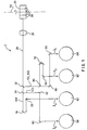
- the ROS optics comprise a collimator 72, a cylinder lens 70, polygon mirror 24, beam splitting mirrors 32, 34, 46 and reflective mirrors 36, 38, 40, 42, 48, 52, 54, 56.
- the laser beams 101, 102, 103 and 104, having wavelengths ⁇ 1 , ⁇ 2 , ⁇ 3 and ⁇ 4 , respectively, produced by beam generating means 74 pass through the collimator 72 and the cylinder lens 70 which direct the beams onto an optical path such that they illuminate a rotating polygon mirror 24 having multiple facets 26.
- the polygon mirror rotates about axis 50, it deflects the beams simultaneously to a scan lens 30 which focuses the beams and corrects for errors such as polygon angle error and wobble.
- the ROS scan lens contains a toroidal element to provide wobble correction.
- the system can use alternative wobble correction means such as, for example, a cylinder mirror following a spherical scan lens, a cylinder mirror following a cylindrical scan lens, or a cylinder mirror following a spherical/cylindrical scan lens, or a cylinder lens very near the photoreceptor.
- the beams from the corrective scan lens 30 are directed along a first optical path 28 to a first optical filter 32
- the first optical filter is, for example, a wavelength selective beam separator comprised of a wavelength selective, multi-layer film for example. Such separators are well known and are discussed and described in Volume 1 of "Applied Optics and Optical Engineering," (1965) edited by R. Kingslake.
- the characteristics of the first optical filter 32 should be chosen such that two beams 103, 104 are passed while the remaining two beams 101, 102 are reflected.
- the passed beams 103, 104 are then separated by another filter 34 of the type described above that reflects one of the beams 103 and passes the other beam 104.
- the reflected beams 101, 102 are similarly separated and reflected based on their wavelengths by the filter 46.
- the filters are selected such that they have an appropriate wavelength sensitive multi-layer film (see, for example, the above-mentioned EP-A-0,547,853).
- each laser beam produces a latent image on its associated photoreceptor 58, 60, 62, 64 that corresponds to a system color that will be transferred onto a recording medium (not shown) such as, for example, plain paper.
- Photoreceptors 58, 60, 62, 64 can be, for example, belts or drums.
- a similar ROS architecture is applicable to a two station configuration for single highlight color, and to a three station configuration for multiple highlight color, as well as to the preferred embodiment of Figure 1 described above for full-color applications using four stations.
- Equalization of optical path lengths results in similarly dimensioned spots at each photoreceptor 58, 60, 62, 64. Equalization of the optical path lengths is significantly easier than adjusting the positions of spatially separated lasers at the input to the collection optics as disclosed in previously described U.S. Patent No. 4,962,312 to Matuura.
- multiple beams 28 can be used to expose different portions of a single photoreceptor 120, such as, for example, a photosensitive belt or drum.
- a single photoreceptor embodiment using, for example, two light beams 101, 102, the different wavelength ⁇ 1 , ⁇ 2 beams 101, 102 are deflected off of a facet 26 of the polygon 24, which is rotating about its central axis 50.
- the beams 101, 102 then pass through a corrective scan optics system 30.
- the beams 101, 102 are separated by a wavelength selective filter 32 of the type described above that reflects one of the beams 101 and passes the other beam 102.
- the beams 101, 102 are then directed to appropriate portions, or image planes, of the photoreceptor 120 by mirrors 110, 112, 114, 116, 118.
- the latent images on the photoreceptor 120 are then transferred to a recording medium, such as, for example plain paper (not shown).
- Figs. 1 and 3 are known as single pass, multicolor printers because a sheet needs to pass by the multiple photoreceptors of Fig. 1, or by the single photoreceptor of Fig. 3 a single time in order to have multiple toner patterns (usually having different colors) deposited thereon.
- the diode spacing is not subject to the extreme design constraints associated with laser diodes that are oriented in a cross scan direction. Since the line of beams produced by the laser diodes is parallel to the fast scan direction, the diode characteristic variations present in devices having a line of diodes arranged in the cross-scan direction, such as, for example, differential bow, and diode crosstalk, are eliminated. Thus, all the advantages associated with multi-layer single optics printing systems are realized, while the need to make closely packed laser diode arrays is avoided.
- the diodes are typically 10 ⁇ m apart.
- the diodes are packed closely together to reduce diode characteristic variations.
- the diode spacing constraint can be relaxed. The diode spacing can be relaxed, for example, to 333 ⁇ m, or 0.33 mm.
- the distance between the first and last diodes in a four laser array would be 1 mm for a 0.33 mm inter-diode spacing. With this spacing, a typical overfilled collimator focal length of 50 mm would have to cover a field of only 0.57 degrees. A collimator can easily be corrected for this small field angle.
- the angle of incidence, in this example, of the beam on the polygon would differ from the first diode to the last diode by 2.28 degrees (4 x 0.57 degrees). Since the angle doubles on reflection off the polygon, the system would have to be designed to cover a scan angle of 4.56 degrees larger than the scan angle that would be required for a single laser diode system. This can easily be done in the design of the optics since 4.56 degrees is typically a small fraction of the total scan angle. For example, typical scan angles are 24 degrees for a 15 facet polygon.
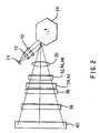
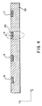
- the laser diodes 3, 4, 6 and 8 could all be fabricated on a single chip 80, as shown in Figure 4, or they can be fabricated on separate chips, as shown in Figure 5, which are then bonded together.
- Multiple wavelength monolithic arrays of diode lasers of the type shown in Figure 4 can be constructed as disclosed in EP-A-0,364,259. From an optical design perspective, the larger divergence angle of the diodes should be in the fast scan direction (denoted by the arrow X in the Figures). This can best be achieved with separate chips as shown in Figure 5.
- Lasers can be assembled as shown in Figure 5 using the techniques described in U.S. Patent No. 4,716,568.
- an insulating material such as, for example, BeO
- the spacers can be, for example, 150 ⁇ m thick while the mounting plates can be, for example, 100 ⁇ m thick.
- four lasers 3, 4, 6, 8 can be easily assembled within 1 mm in the fast can direction.
- alignment marks and micropositioning in the assembly process it should be possible to place the chips within 2 ⁇ m of a line in the fast scan direction, shown by the arrow X.
- the larger divergence angle 90 will be perpendicular to the fast scan direction shown by the arrow Y.
- the Figure 4 configuration will also work but will require a longer focal length, larger diameter collimator.
- a logical extension to the architectures described above is to fabricate multiple lines of, for example, four diode arrays on a single chip in a two dimensional array.
- Such a staggered array can be fabricated monolithically by separately addressing lasers grown on a grooved substrate as described in U.S. Patent No. 4,786,918.
- Arrays as large as 4x4 can be obtained by combining two of the staggered arrays.
- 4x4 arrays can be obtained by replacing the separate single lasers with linear monolithic arrays of four diodes operating at the same wavelength. Independent addressing of each laser in each monolithic array is accomplished by patterning the metal on the mounting plate and spacer.
- Simultaneous writing of multiple lines achieved in these ways can be used to increase the speed of the system. That is, the output beams from each diode array would be directed to each of the stations instead of the output beam from a single diode for each station as described above.
- ROS architecture has been described that enables multiple laser diodes, having widely separated wavelengths, to be spaced a convenient distance apart because the diodes are arranged in a line extending in a direction parallel to the fast-scan direction of the ROS (i.e., perpendicular to the axis of rotation of the polygon mirror). This increased spacing simplifies the fabrication of the diodes, eliminates crosstalk, and eliminates the inconsistencies in beam characteristics between the light beams that exist when a line of diodes are spaced from each other in the cross- scan direction.
- the laser diodes can be fabricated on a single chip, or comprise individual diodes mounted on a mechanical structure, and positioned as close to each other as is convenient, using conventional laser diode fabricating techniques, on a line that is parallel to the fast scan direction of the ROS.
- Multiple lines of multi- diode arrays on a single chip or fabricated monolithically, can be used to achieve increased system speed.
- only a single optical system is required providing a very significant cost reduction over systems having plural optical systems.
Landscapes
- Physics & Mathematics (AREA)
- Engineering & Computer Science (AREA)
- General Physics & Mathematics (AREA)
- Optics & Photonics (AREA)
- General Engineering & Computer Science (AREA)
- Theoretical Computer Science (AREA)
- Mechanical Optical Scanning Systems (AREA)
- Facsimile Scanning Arrangements (AREA)
- Laser Beam Printer (AREA)
- Printers Or Recording Devices Using Electromagnetic And Radiation Means (AREA)
Claims (8)
- Dispositif de balayage de sortie de type trame comprenant :des moyens de génération de faisceaux (74) pour générer de multiples faisceaux lumineux présentant des longueurs d'onde dissemblables et étant disposés en une ligne, ladite ligne étant perpendiculaire à une direction dans laquelle lesdits multiples faisceaux lumineux se déplacent ;un miroir en forme de polygone (24) monté à tourner sur un axe central (50) et placé dans un trajet pour dévier simultanément lesdits multiples faisceaux lumineux, desdits multiples faisceaux lumineux disposés dans la ligne, ledit axe central étant conçu pour s'étendre perpendiculaire à ladite ligne desdits faisceaux lumineux, chaque faisceau de ladite multitude de faisceaux lumineux restant séparé pendant la déviation à partir du miroir en forme de polygone ; etdes moyens de séparateur optique (32, 34, 46) pour laisser passer et réfléchir différemment lesdits faisceaux lumineux sur un trajet optique différent pour chaque faisceau lumineux.
- Dispositif de balayage de sortie du type trame selon la revendication 1, dans lequel :
lesdits moyens de séparateur optique laissent passer et réfléchissent différemment lesdits faisceaux lumineux sur la base de leur longueur d'onde. - Dispositif de balayage de sortie de type trame selon la revendication 1 ou la revendication 2, dans lequel :
lesdits multiples faisceaux lumineux sont simultanément déviés par une seule facette (26) dudit miroir en forme de polygone. - Dispositif de balayage de sortie du type trame selon l'une quelconque des revendications précédentes, comprenant : .des moyens optiques (72, 74) pour focaliser lesdits multiples faisceaux lumineux sur ledit miroir en forme de polygone ; etdes moyens de lentille de balayage (30) pour focaliser lesdits multiples faisceaux lumineux déviés par ledit miroir en forme de polygone et pour corriger les erreurs dans lesdits multiples faisceaux lumineux.
- Dispositif de balayage de sortie de type trame selon l'une quelconque des revendications précédentes, dans lequel les moyens de génération de faisceaux peuvent être mis en oeuvre pour générer quatre faisceaux lumineux et les moyens de séparateur optique comprennent :un premier séparateur optique (32) disposé sur un premier trajet optique pour diriger un premier faisceau lumineux (101) et un second faisceau lumineux (102) sur un second trajet optique disparate et pour diriger un troisième faisceau lumineux (103) et un quatrième faisceau lumineux (104) sur un troisième trajet optique disparate ;un second séparateur optique (46) disposé sur ledit second trajet optique pour diriger ledit premier faisceau lumineux sur un quatrième trajet optique disparate et pour diriger ledit second faisceau lumineux sur un cinquième trajet optique disparate ;un troisième séparateur optique- (34) disposé sur ledit troisième trajet optique pour diriger ledit troisième faisceau lumineux sur un sixième trajet optique disparate et pour diriger ledit quatrième faisceau lumineux sur un septième trajet optique disparate.
- Dispositif de balayage de sortie de type trame selon l'une quelconque des revendications précédentes, dans lequel ledit moyen de génération de faisceaux comprend une multitude de diodes lasers disposées sur une seule puce (80) ou sur une multitude de puces fixées solidairement les unes aux autres.
- Imprimante comprenant un dispositif de balayage de sortie de type trame selon l'une quelconque des revendications 1 à 6, et un photorécepteur respectif (58, 60, 62, 64) pour recevoir chacun desdits faisceaux lumineux.
- Imprimante comprenant un dispositif de balayage de sortie de type trame selon l'une quelconque des revendications 1 à 6, et
un photorécepteur pour recevoir chacun desdits faisceaux lumineux sur une surface photoréceptrice disparate de celui-ci.
Applications Claiming Priority (2)
| Application Number | Priority Date | Filing Date | Title |
|---|---|---|---|
| US07/948,512 US5341158A (en) | 1992-09-22 | 1992-09-22 | Raster output scanner for a xerographic printing system having laser diodes arranged in a line parallel to the fast scan direction |
| US948512 | 1997-10-10 |
Publications (2)
| Publication Number | Publication Date |
|---|---|
| EP0589652A1 EP0589652A1 (fr) | 1994-03-30 |
| EP0589652B1 true EP0589652B1 (fr) | 1997-05-02 |
Family
ID=25487933
Family Applications (1)
| Application Number | Title | Priority Date | Filing Date |
|---|---|---|---|
| EP93307410A Expired - Lifetime EP0589652B1 (fr) | 1992-09-22 | 1993-09-20 | Dispositif de balayage à trame pour un système d'impression xérographique, ayant des diodes laser disposées en ligne droite, parallèle à la direction de balayage rapide |
Country Status (4)
| Country | Link |
|---|---|
| US (1) | US5341158A (fr) |
| EP (1) | EP0589652B1 (fr) |
| JP (1) | JPH06118322A (fr) |
| DE (1) | DE69310301T2 (fr) |
Families Citing this family (13)
| Publication number | Priority date | Publication date | Assignee | Title |
|---|---|---|---|---|
| US5532812A (en) * | 1994-04-12 | 1996-07-02 | Samsung Electronics Co., Ltd. | Apparatus for forming a copy of an original image on a sheet of paper |
| US5543829A (en) | 1994-10-19 | 1996-08-06 | Xerox Corporation | Method and apparatus for adjusting the curvature of a folding mirror in a raster scanning system |
| US5563647A (en) | 1994-10-24 | 1996-10-08 | Xerox Corporation | Method and apparatus for reducing differences in image heights of images generated by plural light beams having dissimilar wavelengths |
| US5617133A (en) * | 1994-10-24 | 1997-04-01 | Xerox Corporation | Method and apparatus for adjusting orientation of light beams in a raster scanning system |
| US5627579A (en) * | 1994-11-29 | 1997-05-06 | Xerox Corporation | Raster scanning optical system and method for adjusting scan line locations on a photoreceptor |
| US5617132A (en) * | 1994-12-01 | 1997-04-01 | Xerox Corporation | Method and apparatus for adjusting the pixel placement in a raster output scanner |
| DE69609400T2 (de) * | 1995-12-22 | 2000-12-07 | Xerox Corp., Rochester | Farbxerographischer Drucker mit vielfachen linearen Reihen von oberflächenemittierenden Lasern mit verschiedenen Wellenlängen |
| ATE221226T1 (de) * | 1996-05-07 | 2002-08-15 | Esko Graphics As | Beleuchterungsverfahren und vorrichtung fuer photosensibele materialen |
| US5854705A (en) * | 1997-01-17 | 1998-12-29 | Xerox Corporation | Micropositioned laser source for raster output scanners |
| US6774923B2 (en) | 2002-05-31 | 2004-08-10 | Lexmark International, Inc. | Dual polygon laser printhead for a color printer |
| KR100433432B1 (ko) * | 2002-09-19 | 2004-05-31 | 삼성전자주식회사 | 레이저프린터의 광주사장치 |
| JP2004212569A (ja) * | 2002-12-27 | 2004-07-29 | Samsung Electronics Co Ltd | 光走査装置 |
| JP2004212615A (ja) * | 2002-12-27 | 2004-07-29 | Samsung Electronics Co Ltd | 光走査装置 |
Citations (1)
| Publication number | Priority date | Publication date | Assignee | Title |
|---|---|---|---|---|
| EP0582454A1 (fr) * | 1992-08-03 | 1994-02-09 | Xerox Corporation | Système d'impression couleur à quatre, toners colorés, à passage simple et utilisant deux unités xérographiques à trois niveaux |
Family Cites Families (18)
| Publication number | Priority date | Publication date | Assignee | Title |
|---|---|---|---|---|
| JPS569763A (en) * | 1979-07-06 | 1981-01-31 | Canon Inc | Beam recording device |
| US4393387A (en) * | 1979-09-14 | 1983-07-12 | Canon Kabushiki Kaisha | Beam recording apparatus effecting the recording by a plurality of beams |
| US4474422A (en) * | 1979-11-13 | 1984-10-02 | Canon Kabushiki Kaisha | Optical scanning apparatus having an array of light sources |
| US4404571A (en) * | 1980-10-14 | 1983-09-13 | Canon Kabushiki Kaisha | Multibeam recording apparatus |
| JPS57116314A (en) * | 1981-01-12 | 1982-07-20 | Canon Inc | Image recorder on multilaser beam scanning system |
| JPS5895361A (ja) * | 1981-12-01 | 1983-06-06 | Canon Inc | カラー画像形成装置 |
| US4716568A (en) * | 1985-05-07 | 1987-12-29 | Spectra Diode Laboratories, Inc. | Stacked diode laser array assembly |
| US4786918A (en) * | 1985-12-12 | 1988-11-22 | Xerox Corporation | Incoherent, optically uncoupled laser arrays for electro-optic line modulators and line printers |
| JPS63120261U (fr) * | 1987-01-30 | 1988-08-03 | ||
| DE3854093T2 (de) * | 1987-04-28 | 1995-11-16 | Canon Kk | Multibilderzeugungsgerät. |
| JPS6477018A (en) * | 1987-09-18 | 1989-03-23 | Fuji Photo Film Co Ltd | Image recording device |
| JPS6481926A (en) * | 1987-09-25 | 1989-03-28 | Fuji Photo Film Co Ltd | Image recording device |
| US5181137A (en) * | 1988-08-24 | 1993-01-19 | Canon Kabushiki Kaisha | Light scanning apparatus |
| JPH0283518A (ja) * | 1988-09-20 | 1990-03-23 | Minolta Camera Co Ltd | レーザビーム走査装置 |
| US5089908A (en) * | 1990-06-29 | 1992-02-18 | Xerox Corporation | Plywood suppression in ROS systems |
| JP2995925B2 (ja) * | 1991-06-14 | 1999-12-27 | ミノルタ株式会社 | レーザビーム合成方法 |
| US5291223A (en) * | 1991-09-19 | 1994-03-01 | Konica Corporation | Exposure unit for a multicolor image forming apparatus capable of better registration of the multicolor images |
| US5243359A (en) * | 1991-12-19 | 1993-09-07 | Xerox Corporation | Raster output scanner for a multistation xerographic printing system |
-
1992
- 1992-09-22 US US07/948,512 patent/US5341158A/en not_active Expired - Lifetime
-
1993
- 1993-06-24 JP JP5153530A patent/JPH06118322A/ja active Pending
- 1993-09-20 EP EP93307410A patent/EP0589652B1/fr not_active Expired - Lifetime
- 1993-09-20 DE DE69310301T patent/DE69310301T2/de not_active Expired - Lifetime
Patent Citations (1)
| Publication number | Priority date | Publication date | Assignee | Title |
|---|---|---|---|---|
| EP0582454A1 (fr) * | 1992-08-03 | 1994-02-09 | Xerox Corporation | Système d'impression couleur à quatre, toners colorés, à passage simple et utilisant deux unités xérographiques à trois niveaux |
Also Published As
| Publication number | Publication date |
|---|---|
| JPH06118322A (ja) | 1994-04-28 |
| DE69310301T2 (de) | 1997-11-06 |
| EP0589652A1 (fr) | 1994-03-30 |
| DE69310301D1 (de) | 1997-06-05 |
| US5341158A (en) | 1994-08-23 |
Similar Documents
| Publication | Publication Date | Title |
|---|---|---|
| JP3257646B2 (ja) | レーザービームプリンター | |
| US5243359A (en) | Raster output scanner for a multistation xerographic printing system | |
| EP0544002B1 (fr) | Dispositif de formation d'image | |
| US5325381A (en) | Multiple beam diode laser output scanning system | |
| EP1942651B1 (fr) | Dispositif de balayage optique et appareil de formation d'images l'utilisant | |
| US5341158A (en) | Raster output scanner for a xerographic printing system having laser diodes arranged in a line parallel to the fast scan direction | |
| EP0573375B1 (fr) | Techniques d'impression utilisant les diodes lasers multiples | |
| JPH1195140A (ja) | マルチビーム露光装置 | |
| EP0781662B1 (fr) | Imprimante xérographique en couleur avec des séries linéaires multiples de lasers à émission par la surface avec des états de polarisation et des longueurs d'onde dissimilaires | |
| US5371526A (en) | Raster output scanner for a single pass printing system which separates plural laser beams by wavelength and polarization | |
| US20040183890A1 (en) | Color image forming appartus | |
| US5617133A (en) | Method and apparatus for adjusting orientation of light beams in a raster scanning system | |
| US5691761A (en) | Method and apparatus for multi-channel printing in a raster output scanning system | |
| US5563647A (en) | Method and apparatus for reducing differences in image heights of images generated by plural light beams having dissimilar wavelengths | |
| US5343224A (en) | Diode laser multiple output scanning system | |
| US5574491A (en) | Apparatus spot position control in an output device employing a linear array of light sources | |
| US20070242717A1 (en) | Two-dimensional surface emitting laser array, multi-beam scanning unit employing the same, and image forming apparatus employing the multi-beam scanning unit | |
| US6593954B2 (en) | Multibeam scanning apparatus with appropriately spaced light source | |
| EP0782928B1 (fr) | Imprimante xérographique en couleur avec des séries linéaires multiples de lasers à émission par la surface avec des longeurs d'onde similaires | |
| JP4481689B2 (ja) | 画像形成装置 | |
| EP0781663B1 (fr) | Imprimante xérographique en couleur avec des séries linéaires multiples de lasers à émission par la surface avec des longueurs d'onde dissimilaires | |
| JP2000180749A (ja) | 光走査装置 | |
| JP2002277780A (ja) | セグメント化されたミラーを用いる複数ビーム式ラスタ出力スキャニングシステム | |
| JPH085944A (ja) | マルチビーム光学装置 | |
| JPH11242169A (ja) | 露光装置 |
Legal Events
| Date | Code | Title | Description |
|---|---|---|---|
| PUAI | Public reference made under article 153(3) epc to a published international application that has entered the european phase |
Free format text: ORIGINAL CODE: 0009012 |
|
| AK | Designated contracting states |
Kind code of ref document: A1 Designated state(s): DE FR GB |
|
| 17P | Request for examination filed |
Effective date: 19940901 |
|
| 17Q | First examination report despatched |
Effective date: 19960208 |
|
| GRAG | Despatch of communication of intention to grant |
Free format text: ORIGINAL CODE: EPIDOS AGRA |
|
| GRAH | Despatch of communication of intention to grant a patent |
Free format text: ORIGINAL CODE: EPIDOS IGRA |
|
| GRAH | Despatch of communication of intention to grant a patent |
Free format text: ORIGINAL CODE: EPIDOS IGRA |
|
| GRAA | (expected) grant |
Free format text: ORIGINAL CODE: 0009210 |
|
| AK | Designated contracting states |
Kind code of ref document: B1 Designated state(s): DE FR GB |
|
| REF | Corresponds to: |
Ref document number: 69310301 Country of ref document: DE Date of ref document: 19970605 |
|
| ET | Fr: translation filed | ||
| PLBE | No opposition filed within time limit |
Free format text: ORIGINAL CODE: 0009261 |
|
| STAA | Information on the status of an ep patent application or granted ep patent |
Free format text: STATUS: NO OPPOSITION FILED WITHIN TIME LIMIT |
|
| 26N | No opposition filed | ||
| REG | Reference to a national code |
Ref country code: GB Ref legal event code: IF02 |
|
| PGFP | Annual fee paid to national office [announced via postgrant information from national office to epo] |
Ref country code: GB Payment date: 20120828 Year of fee payment: 20 |
|
| PGFP | Annual fee paid to national office [announced via postgrant information from national office to epo] |
Ref country code: DE Payment date: 20120827 Year of fee payment: 20 Ref country code: FR Payment date: 20121004 Year of fee payment: 20 |
|
| REG | Reference to a national code |
Ref country code: DE Ref legal event code: R071 Ref document number: 69310301 Country of ref document: DE |
|
| REG | Reference to a national code |
Ref country code: GB Ref legal event code: PE20 Expiry date: 20130919 |
|
| PG25 | Lapsed in a contracting state [announced via postgrant information from national office to epo] |
Ref country code: DE Free format text: LAPSE BECAUSE OF EXPIRATION OF PROTECTION Effective date: 20130921 |
|
| PG25 | Lapsed in a contracting state [announced via postgrant information from national office to epo] |
Ref country code: GB Free format text: LAPSE BECAUSE OF EXPIRATION OF PROTECTION Effective date: 20130919 |