EP0590160B1 - Flachblasformmaschine, flachblasformverfahren und produkte durch flachblasformen - Google Patents
Flachblasformmaschine, flachblasformverfahren und produkte durch flachblasformen Download PDFInfo
- Publication number
- EP0590160B1 EP0590160B1 EP93908118A EP93908118A EP0590160B1 EP 0590160 B1 EP0590160 B1 EP 0590160B1 EP 93908118 A EP93908118 A EP 93908118A EP 93908118 A EP93908118 A EP 93908118A EP 0590160 B1 EP0590160 B1 EP 0590160B1
- Authority
- EP
- European Patent Office
- Prior art keywords
- core
- die
- flattened
- flat
- blow molding
- Prior art date
- Legal status (The legal status is an assumption and is not a legal conclusion. Google has not performed a legal analysis and makes no representation as to the accuracy of the status listed.)
- Expired - Lifetime
Links
- 238000000071 blow moulding Methods 0.000 title claims abstract description 22
- 238000001125 extrusion Methods 0.000 claims description 6
- 238000000034 method Methods 0.000 claims description 5
- 230000008602 contraction Effects 0.000 abstract description 3
- 239000011347 resin Substances 0.000 description 8
- 229920005989 resin Polymers 0.000 description 8
- 238000002347 injection Methods 0.000 description 6
- 239000007924 injection Substances 0.000 description 6
- 238000010276 construction Methods 0.000 description 5
- 230000004048 modification Effects 0.000 description 2
- 238000012986 modification Methods 0.000 description 2
- 238000005034 decoration Methods 0.000 description 1
- 230000001419 dependent effect Effects 0.000 description 1
- 238000010438 heat treatment Methods 0.000 description 1
- 238000004519 manufacturing process Methods 0.000 description 1
- 238000000465 moulding Methods 0.000 description 1
Images


Classifications
-
- B—PERFORMING OPERATIONS; TRANSPORTING
- B29—WORKING OF PLASTICS; WORKING OF SUBSTANCES IN A PLASTIC STATE IN GENERAL
- B29C—SHAPING OR JOINING OF PLASTICS; SHAPING OF MATERIAL IN A PLASTIC STATE, NOT OTHERWISE PROVIDED FOR; AFTER-TREATMENT OF THE SHAPED PRODUCTS, e.g. REPAIRING
- B29C49/00—Blow-moulding, i.e. blowing a preform or parison to a desired shape within a mould; Apparatus therefor
- B29C49/02—Combined blow-moulding and manufacture of the preform or the parison
- B29C49/04—Extrusion blow-moulding
- B29C49/04116—Extrusion blow-moulding characterised by the die
-
- B—PERFORMING OPERATIONS; TRANSPORTING
- B29—WORKING OF PLASTICS; WORKING OF SUBSTANCES IN A PLASTIC STATE IN GENERAL
- B29C—SHAPING OR JOINING OF PLASTICS; SHAPING OF MATERIAL IN A PLASTIC STATE, NOT OTHERWISE PROVIDED FOR; AFTER-TREATMENT OF THE SHAPED PRODUCTS, e.g. REPAIRING
- B29C48/00—Extrusion moulding, i.e. expressing the moulding material through a die or nozzle which imparts the desired form; Apparatus therefor
- B29C48/03—Extrusion moulding, i.e. expressing the moulding material through a die or nozzle which imparts the desired form; Apparatus therefor characterised by the shape of the extruded material at extrusion
- B29C48/07—Flat, e.g. panels
-
- B—PERFORMING OPERATIONS; TRANSPORTING
- B29—WORKING OF PLASTICS; WORKING OF SUBSTANCES IN A PLASTIC STATE IN GENERAL
- B29C—SHAPING OR JOINING OF PLASTICS; SHAPING OF MATERIAL IN A PLASTIC STATE, NOT OTHERWISE PROVIDED FOR; AFTER-TREATMENT OF THE SHAPED PRODUCTS, e.g. REPAIRING
- B29C48/00—Extrusion moulding, i.e. expressing the moulding material through a die or nozzle which imparts the desired form; Apparatus therefor
- B29C48/03—Extrusion moulding, i.e. expressing the moulding material through a die or nozzle which imparts the desired form; Apparatus therefor characterised by the shape of the extruded material at extrusion
- B29C48/09—Articles with cross-sections having partially or fully enclosed cavities, e.g. pipes or channels
- B29C48/11—Articles with cross-sections having partially or fully enclosed cavities, e.g. pipes or channels comprising two or more partially or fully enclosed cavities, e.g. honeycomb-shaped
-
- B—PERFORMING OPERATIONS; TRANSPORTING
- B29—WORKING OF PLASTICS; WORKING OF SUBSTANCES IN A PLASTIC STATE IN GENERAL
- B29C—SHAPING OR JOINING OF PLASTICS; SHAPING OF MATERIAL IN A PLASTIC STATE, NOT OTHERWISE PROVIDED FOR; AFTER-TREATMENT OF THE SHAPED PRODUCTS, e.g. REPAIRING
- B29C48/00—Extrusion moulding, i.e. expressing the moulding material through a die or nozzle which imparts the desired form; Apparatus therefor
- B29C48/03—Extrusion moulding, i.e. expressing the moulding material through a die or nozzle which imparts the desired form; Apparatus therefor characterised by the shape of the extruded material at extrusion
- B29C48/12—Articles with an irregular circumference when viewed in cross-section, e.g. window profiles
-
- B—PERFORMING OPERATIONS; TRANSPORTING
- B29—WORKING OF PLASTICS; WORKING OF SUBSTANCES IN A PLASTIC STATE IN GENERAL
- B29C—SHAPING OR JOINING OF PLASTICS; SHAPING OF MATERIAL IN A PLASTIC STATE, NOT OTHERWISE PROVIDED FOR; AFTER-TREATMENT OF THE SHAPED PRODUCTS, e.g. REPAIRING
- B29C48/00—Extrusion moulding, i.e. expressing the moulding material through a die or nozzle which imparts the desired form; Apparatus therefor
- B29C48/25—Component parts, details or accessories; Auxiliary operations
- B29C48/30—Extrusion nozzles or dies
- B29C48/32—Extrusion nozzles or dies with annular openings, e.g. for forming tubular articles
- B29C48/325—Extrusion nozzles or dies with annular openings, e.g. for forming tubular articles being adjustable, i.e. having adjustable exit sections
-
- B—PERFORMING OPERATIONS; TRANSPORTING
- B29—WORKING OF PLASTICS; WORKING OF SUBSTANCES IN A PLASTIC STATE IN GENERAL
- B29C—SHAPING OR JOINING OF PLASTICS; SHAPING OF MATERIAL IN A PLASTIC STATE, NOT OTHERWISE PROVIDED FOR; AFTER-TREATMENT OF THE SHAPED PRODUCTS, e.g. REPAIRING
- B29C49/00—Blow-moulding, i.e. blowing a preform or parison to a desired shape within a mould; Apparatus therefor
- B29C49/02—Combined blow-moulding and manufacture of the preform or the parison
- B29C49/04—Extrusion blow-moulding
- B29C49/0411—Means for defining the wall or layer thickness
- B29C49/04114—Means for defining the wall or layer thickness for keeping constant thickness
-
- B—PERFORMING OPERATIONS; TRANSPORTING
- B29—WORKING OF PLASTICS; WORKING OF SUBSTANCES IN A PLASTIC STATE IN GENERAL
- B29C—SHAPING OR JOINING OF PLASTICS; SHAPING OF MATERIAL IN A PLASTIC STATE, NOT OTHERWISE PROVIDED FOR; AFTER-TREATMENT OF THE SHAPED PRODUCTS, e.g. REPAIRING
- B29C49/00—Blow-moulding, i.e. blowing a preform or parison to a desired shape within a mould; Apparatus therefor
- B29C49/071—Preforms or parisons characterised by their configuration, e.g. geometry, dimensions or physical properties
-
- B—PERFORMING OPERATIONS; TRANSPORTING
- B29—WORKING OF PLASTICS; WORKING OF SUBSTANCES IN A PLASTIC STATE IN GENERAL
- B29C—SHAPING OR JOINING OF PLASTICS; SHAPING OF MATERIAL IN A PLASTIC STATE, NOT OTHERWISE PROVIDED FOR; AFTER-TREATMENT OF THE SHAPED PRODUCTS, e.g. REPAIRING
- B29C2949/00—Indexing scheme relating to blow-moulding
- B29C2949/07—Preforms or parisons characterised by their configuration
- B29C2949/075—Preforms or parisons characterised by their configuration having at least one internal separating wall
-
- B—PERFORMING OPERATIONS; TRANSPORTING
- B29—WORKING OF PLASTICS; WORKING OF SUBSTANCES IN A PLASTIC STATE IN GENERAL
- B29C—SHAPING OR JOINING OF PLASTICS; SHAPING OF MATERIAL IN A PLASTIC STATE, NOT OTHERWISE PROVIDED FOR; AFTER-TREATMENT OF THE SHAPED PRODUCTS, e.g. REPAIRING
- B29C2949/00—Indexing scheme relating to blow-moulding
- B29C2949/30—Preforms or parisons made of several components
- B29C2949/3006—Preforms or parisons made of several components having tangentially different components within one layer, e.g. longitudinal stripes
-
- B—PERFORMING OPERATIONS; TRANSPORTING
- B29—WORKING OF PLASTICS; WORKING OF SUBSTANCES IN A PLASTIC STATE IN GENERAL
- B29C—SHAPING OR JOINING OF PLASTICS; SHAPING OF MATERIAL IN A PLASTIC STATE, NOT OTHERWISE PROVIDED FOR; AFTER-TREATMENT OF THE SHAPED PRODUCTS, e.g. REPAIRING
- B29C49/00—Blow-moulding, i.e. blowing a preform or parison to a desired shape within a mould; Apparatus therefor
- B29C49/02—Combined blow-moulding and manufacture of the preform or the parison
- B29C49/04—Extrusion blow-moulding
- B29C49/041—Extrusion blow-moulding using an accumulator head
-
- F—MECHANICAL ENGINEERING; LIGHTING; HEATING; WEAPONS; BLASTING
- F24—HEATING; RANGES; VENTILATING
- F24S—SOLAR HEAT COLLECTORS; SOLAR HEAT SYSTEMS
- F24S10/00—Solar heat collectors using working fluids
- F24S10/70—Solar heat collectors using working fluids the working fluids being conveyed through tubular absorbing conduits
- F24S10/73—Solar heat collectors using working fluids the working fluids being conveyed through tubular absorbing conduits the tubular conduits being of plastic material
Definitions
- the present invention relates to a flat blow molding machine according to the generic part of the independent claim.
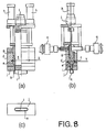
- the present applicant previously developed a flat blow molding machine which does not extrude the cylindrical parison "a”, but extrudes a hollow flattened parison, that matches an inner wall of thin metallic molds "b” and "c", from the clearance between a planar flattened core and a flattened die surrounding the core so as to mold a hollow plate-like product having a uniform thickness.
- FIG. 8 This type of flat blow molding machine is constructed as shown in Figure 8: an accumulator chamber "e” whose section is flattened is formed in a housing "d” in a vertical direction, a planar flattened mandrel “f” is vertically provided at the center of the accumulator chamber “e” and a flattened piston “g” is fitted over the flattened mandrel "f”.
- the flattened piston "g” is lowered by a hydraulic cylinder “h” to pressurize a resin in the accumulator chamber “e” and the pressurized resin is extruded in the form of a hollow flattened parison "k” from the clearance between a flattened core "i” provided at the tip of the flattened mandrel "f” and a flattened die “j” provided at the lower end of the housing "d".
- the resin is fed to the accumulator chamber “e” from extruders "q" provided on the left and right sides in its thickness Y direction.
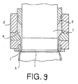
- the flattened parison "k” extruded as shown in Figure 9 is sandwiched by flattened metallic molds (not shown) in a direction perpendicular to the drawing sheet, and air is blown in.
- the problem to be solved by the present invention is to provide a flat blow molding machine which can change the width of a flattened parison injected from the molding machine.
- the invention provides a flat blow molding machine which injects hollow flattened parison from the clearance between a flattened core and a flattened die surrounding the core, comprising the features stated in the independent claim.
- Dependent claim 3 describes a method of changing the shape of an extrusion gap of a machine according to the invention.
- the ends of the die are slid in the width direction respectively and the core is appropriately replaced upon the expansion/contraction of the die in the width direction, it is possible to change the width of the hollow flattened parison to be injected from the clearance between the core and the die.
- the flattened core includes a replaceable planar part and non-replaceable curved parts and only the replacable part is loaded and unloaded, the cost is reduced, since it will be sufficient to prepare a plurality of replaceable planar parts of different lengths which are less costly to manufacture.
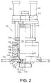
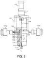
- FIG. 2 illustrates a front view of a flat blow molding machine 101 and Figure 3 illustrates its lateral view.
- a flattened accumulator chamber 103 having a width X and a thickness Y is formed in a flattened main body 102.
- a plasticized resin is supplied from two extruders 104a and 104b located left and right in the width Y direction. It should be noted that only one extruder 104a/104b may be provided together with a distribution value (not shown) and the resin may be supplied into the accumulator chamber 103 through the distribution valve.
- a flattened piston 105 is slidable in up and down directions.
- the flattened piston 105 is connected to a hydraulic cylinder 107 located above the main body 102 via an intermediate member 106. According to this construction, if the hydraulic cylinder 107 expands/contracts, the flattened piston 105 slides up and down in the accumulator chamber 103 to press the resin.
- a flattened opening 108 extends vertically in the flat piston 105, and a planar mandrel 109 is inserted in the opening 108.
- the upper end of the mandrel 109 is connected to an actuator 111 (cylinder mechanism) above the main body 102 via an intermediate member 110, and a flattened core 112 is mounted on the lower end of the mandrel 109.
- a flattened die 113 surrounds the core 112 at a prescribed clearance.
- the die 113 is mounted on the lower end of the main body 102 by means of a plate 115 and a holder 114.
- the flat piston 105 compresses the resin in the accumulator chamber 103, the pressed resin is extruded from the clearance between the flat die 113 and the flat core 112 as a flattened parison 116.
- the actuator 111 is manipulated to move the core 112 up and down so as to adjust the clearance (gap) between the die 113 and the core 112, it is possible to control the thickness (wall thickness) of the extruded flat parison 116 in the extruding direction.
- the flattened die 113 includes a straight portion 113a at the center and corner portions 113b at the ends.
- the straight portion 113a is constructed by two planar blocks 117 extending parallel to each other at a prescribed clearance.
- the corner portion 113b includes a slide piece 118 slidably sandwiched by these planar blocks 117.
- the slide piece 118 has a U-shaped curved (three dimensional) portion 118a and is slid in a width direction by an actuator 119 (hydraulic cylinder) supported by the die holder 114.
- a hydraulic cylinder is employed as the actuator 119.
- it is not limited to this.
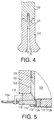
- it may be a stepping motor or a feed screw mechanism 119a as illustrated in Figure 5.
- the slide piece 118 is moved by the actuator 119 in the width direction and fixed at a desired position.
- the core 112 is constructed by a planar replaceable (or interchangeable) portion 112b located at the center and curved non-replaceable portions 112a located at the ends, as shown in Figures 1(a) and (c).
- the replaceable portion 112a is a planar member having the same thickness as the planar mandrel 109.
- the non-replaceable portion 112a is a member having a projection-like curved portion 112c which engages a recess-like curved portion 118a of the slide piece 118.
- the replaceable portion 112b and the non-replaceable portions 112a are respectively mounted on the lower end of the planar mandrel 109 by bolts 120. This is illustrated in Figure 4.
- connection 121 for the lower end of the flattened mandrel 109 and an upper end of the core 112 (replaceable portion 112b and non-replaceable portions 112a) is a faucet joint so that accurate positioning of these two elements is ensured.
- a hexagon socket head cap screw may be employed instead of a common hexagon head bolt 120.
- the recess-like curved (three dimensional) portion 118a and the projection-like curved portion 112c are formed on the slide piece 118 of the flattened die 113 and on the non-replaceable portion 112a of the flattened core 112, respectively.
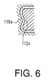
- the slide piece 118a and the non-replaceable portion 112a may have a wavy curved portion at their centers, respectively, as shown in Figure 6. If this construction is employed, the concave center portion expands appropriately upon air injection so that the outer face of the parison 116 contacts the inner wall of a metallic mold substantially simultaneously. Thus, it is possible to make the thickness of the product uniform.
- the flattened parison 116 is extruded from the clearance between the flattened die 113 and the flattened core 112, as shown in Figures 2 and 3.
- the bolt 120 which mounts the flattened core 112 (replaceable portion 112b and non-replaceable portions 112a) onto the tip of the planar mandrel 109 is removed and the replaceable portion 112b and the non-replaceable portions 112a are removed from the mandrel 109. Then, one or both of left and right slide pieces of the flattened die 113 are slid by the actuator 119 such that they approach each other to reduce the width of the flattened die 113.
- the core 112 since the core 112 includes the replaceable portion 112b at the center and the non-replaceable portions 112a at the ends and only the portion 112b is to be replaced, a plurality of inexpensive and straight (planar) replaceable portions 112b having different lengths will be required only. This reduces the cost.
- the actuator 111 is advanced/retracted upon signals from a gap setting device (not shown) during the injection of flattened parison 116 to move the flattened core 112 up and down appropriately via the mandrel 109, the clearance (gap) between the core 112 and the die 113 varies so that it is possible to adjust the thickness profile of the flattened parison 116 in the injection direction (longitudinal direction).
- the actuator 119 is advanced/retracted upon other signals from the gap setting device during the injection of the flatted parison 116 to move the slide piece 118 appropriately right and left, it is possible to adjust the thickness profile of the flattened parison 116 in the width direction.
Landscapes
- Engineering & Computer Science (AREA)
- Mechanical Engineering (AREA)
- Manufacturing & Machinery (AREA)
- Physics & Mathematics (AREA)
- Geometry (AREA)
- Blow-Moulding Or Thermoforming Of Plastics Or The Like (AREA)
- Processing And Handling Of Plastics And Other Materials For Molding In General (AREA)
Claims (4)
- Flachblasformmaschine (101) zum Extrudieren eines hohlen Formlings (116) mit abgeflachtem Ringquerschnitt aus einem Formling-Extrusionsspalt am Unterteil der Flachblasformmaschine (101), der definiert ist durch einen abgeflachten Kern (112) und ein diesen umgebendes Werkzeug (113), wobei der Kern Schiebestücke (118) aufweist, dadurch gekennzeichnet, daß der Kern (112) ein erstes abgerundetes Endteil (112a), ein zweites abgerundetes Endteil und ein zentrales flaches Teil (112b) zwischen dem ersten und dem zweiten Endteil (112a) hat, daß das erste und das zweite Endteil (112a) und das flache Teil (112b) an dem unteren Ende eines Dorns (109) lösbar befestigt sind, daß das flache Teil (112b) auswechselbar ist, wenn die abgeflachte Form des Kerns in Längsrichtung des flachen Teils verlängert oder geschrumpft ist, und daß die Schiebestücke (118) des Werkzeugs (113) entsprechend einer Formänderung des Kerns (112) derart bewegt werden, daß die Dicke des Formlings konstant gehalten wird.
- Flachblasformmaschine (101) nach Anspruch 1, dadurch gekennzeichnet, daß das erste und das zweite Endteil (112a) und das flache Teil (112b) am unteren Ende des Dorns (109) mit Bolzen (120) befestigt sind.
- Verfahren zum Ändern der Form eines abgeflachten Formling-Extrusionsspalts einer Flachblasformmaschine (101) nach Anspruch 1 oder 2, bei der der Formling-Extrusionsspalt durch einen abgeflachten Kern (112) gebildet ist, der am unteren Ende des Dorns (109) befestigt ist und ein Werkzeug (113, 118) den Kern (112) umgibt, mit folgenden Schritten:A) lösbares Befestigen des ersten und des zweiten abgerundeten Endteils (112a) und des flachen Teils (112b) jeweils am unteren Ende des Dorns (109);B) Lösen des ersten und des zweiten abgerundeten Endteils (112a) und des flachen Teils (112b) jeweils vom unteren Ende des Dorns (109), wenn die Form des Formling-Extrusionsspalts zu ändern ist;C) Ersetzen des flachen Teils (112b) durch ein anderes flaches Teil (112b) mit unterschiedlicher Form;D) Bewegen des Werkzeugs (118) in Längsrichtung des flachen Teils (112b) entsprechend der Form des anderen flachen Teils (112b); undE) Befestigen des anderen flachen Teils (112b) und des ersten und des zweiten abgerundeten Endteils (112a) jeweils am unteren Ende des Dorns (109) zum Bilden einer anderen Form des Formling-Extrusionsspalts.
- Verfahren nach Anspruch 3, dadurch gekennzeichnet, daß der Schritt A) mittels Bolzen (120) ausgeführt wird.
Applications Claiming Priority (13)
| Application Number | Priority Date | Filing Date | Title |
|---|---|---|---|
| JP9970892A JP3106677B2 (ja) | 1992-04-20 | 1992-04-20 | 偏平ブロー成形装置 |
| JP99708/92 | 1992-04-20 | ||
| JP122111/92 | 1992-05-14 | ||
| JP04122111A JP3118954B2 (ja) | 1992-05-14 | 1992-05-14 | 偏平ブロー成形装置 |
| JP12745992A JP3196316B2 (ja) | 1992-05-20 | 1992-05-20 | ブロー成形装置 |
| JP127459/92 | 1992-05-20 | ||
| JP13362492A JPH05318563A (ja) | 1992-05-26 | 1992-05-26 | ブロー成形方法ならびに成形装置および成形品 |
| JP133624/92 | 1992-05-26 | ||
| JP162996/92 | 1992-06-22 | ||
| JP16299692A JP3196326B2 (ja) | 1992-06-22 | 1992-06-22 | 偏平ブロー成形装置 |
| JP175492/92 | 1992-07-02 | ||
| JP17549292A JP3125443B2 (ja) | 1992-07-02 | 1992-07-02 | 偏平ブロー成形装置 |
| PCT/JP1993/000509 WO1993020997A1 (fr) | 1992-04-20 | 1993-04-20 | Machine d'extrusion-soufflage plat, procede d'extrusion-soufflage plat et produit d'extrusion-soufflage plat |
Publications (3)
| Publication Number | Publication Date |
|---|---|
| EP0590160A1 EP0590160A1 (de) | 1994-04-06 |
| EP0590160A4 EP0590160A4 (de) | 1994-11-23 |
| EP0590160B1 true EP0590160B1 (de) | 1998-04-08 |
Family
ID=27565525
Family Applications (1)
| Application Number | Title | Priority Date | Filing Date |
|---|---|---|---|
| EP93908118A Expired - Lifetime EP0590160B1 (de) | 1992-04-20 | 1993-04-20 | Flachblasformmaschine, flachblasformverfahren und produkte durch flachblasformen |
Country Status (1)
| Country | Link |
|---|---|
| EP (1) | EP0590160B1 (de) |
Families Citing this family (1)
| Publication number | Priority date | Publication date | Assignee | Title |
|---|---|---|---|---|
| IT1261264B (it) * | 1993-09-16 | 1996-05-09 | Saiag Ind Spa | Procedimento e dispositivo per la produzione di tubazioni di raccordo e relativa tubazione. |
Family Cites Families (5)
| Publication number | Priority date | Publication date | Assignee | Title |
|---|---|---|---|---|
| JPS4936387Y1 (de) * | 1969-08-06 | 1974-10-03 | ||
| JPS5030958A (de) * | 1973-07-18 | 1975-03-27 | ||
| IT1037808B (it) * | 1975-05-02 | 1979-11-20 | Covema Srl | Impianto per la realizzazione particolarmente di profilati cavi in materia plastica |
| JPS6392416A (ja) * | 1986-10-07 | 1988-04-22 | Ishikawajima Harima Heavy Ind Co Ltd | ブロ−成形機におけるパリソンの肉厚調整装置 |
| JPH0796256B2 (ja) * | 1989-10-24 | 1995-10-18 | 宇部興産株式会社 | 扁平ダイスを有するブロー成形機 |
-
1993
- 1993-04-20 EP EP93908118A patent/EP0590160B1/de not_active Expired - Lifetime
Also Published As
| Publication number | Publication date |
|---|---|
| EP0590160A4 (de) | 1994-11-23 |
| EP0590160A1 (de) | 1994-04-06 |
Similar Documents
| Publication | Publication Date | Title |
|---|---|---|
| EP1864782B1 (de) | Verfahren zur Herstellung von Hohlkörpern aus Kunststoff mit Einlageteilen an der Innen- bzw. Aussenseite | |
| CN101466524A (zh) | 通过挤吹成型及连续的喷嘴缝隙调节制造热塑性塑料空心体的方法 | |
| US7736141B2 (en) | System for changing a mold in a die casting machine | |
| EP0885108B1 (de) | ELEKTROMECHANISCHE ANTRIEBSANLAGE FüR SPEICHERKöPFE | |
| EP0693358B1 (de) | Verfahren zum Herstellen von blasgeformten Gegenständen | |
| US6033204A (en) | Flat blow molding machine, flat blow method and products of flat blow molding | |
| DE3429141C2 (de) | Verfahren zur Herstellung eines Hohlkörpers | |
| US5840232A (en) | Multi-layer parison extrusion system | |
| CN212795820U (zh) | 一种多料道挤塑模头 | |
| KR101978248B1 (ko) | 크기조절이 가능한 다층 성형식 벽돌금형 | |
| EP3895876B1 (de) | Extrusionssystem und verfahren zur verarbeitung von reifenrohlingen | |
| CN111844684A (zh) | 一种多料道挤塑模头 | |
| JP3106677B2 (ja) | 偏平ブロー成形装置 | |
| EP0549823B1 (de) | Vorrichtung zum Wechseln von Werkzeugen bei Blasformmaschinen | |
| US5792486A (en) | Retainer for the die pin in an accumulator head | |
| CN113787701B (zh) | 一种吹瓶机及其吹瓶生产方法 | |
| EP0590160A1 (de) | Flachblasformmaschine, flachblasformverfahren und produkte durch flachblasformen | |
| KR101562250B1 (ko) | 압출 중공 성형기의 에어 공급장치 | |
| CN214160913U (zh) | 一种铝合金自动化挤压成型装置 | |
| US20020180115A1 (en) | Method and apparatus for in-mold separation of integrally attached gutter flash from a blow-molded thermoplastic resin product | |
| CN218366299U (zh) | 一种塑料积木制造用模具 | |
| CN224145235U (zh) | 注塑机器人模具快速更换组件 | |
| CN213227492U (zh) | 一种人体模特肢体生产用成型装置 | |
| CN217346641U (zh) | 一种吹塑机吹气装置 | |
| US6482350B1 (en) | Low profile blow pin assembly for a rotary blow molding machine and method of blow molding |
Legal Events
| Date | Code | Title | Description |
|---|---|---|---|
| PUAI | Public reference made under article 153(3) epc to a published international application that has entered the european phase |
Free format text: ORIGINAL CODE: 0009012 |
|
| 17P | Request for examination filed |
Effective date: 19940118 |
|
| AK | Designated contracting states |
Kind code of ref document: A1 Designated state(s): DE FR GB IT |
|
| A4 | Supplementary search report drawn up and despatched | ||
| AK | Designated contracting states |
Kind code of ref document: A4 Designated state(s): DE FR GB IT |
|
| 17Q | First examination report despatched |
Effective date: 19960626 |
|
| GRAG | Despatch of communication of intention to grant |
Free format text: ORIGINAL CODE: EPIDOS AGRA |
|
| GRAG | Despatch of communication of intention to grant |
Free format text: ORIGINAL CODE: EPIDOS AGRA |
|
| GRAH | Despatch of communication of intention to grant a patent |
Free format text: ORIGINAL CODE: EPIDOS IGRA |
|
| GRAH | Despatch of communication of intention to grant a patent |
Free format text: ORIGINAL CODE: EPIDOS IGRA |
|
| GRAA | (expected) grant |
Free format text: ORIGINAL CODE: 0009210 |
|
| AK | Designated contracting states |
Kind code of ref document: B1 Designated state(s): DE FR GB IT |
|
| REF | Corresponds to: |
Ref document number: 69317842 Country of ref document: DE Date of ref document: 19980514 |
|
| ITF | It: translation for a ep patent filed | ||
| ET | Fr: translation filed | ||
| PLBE | No opposition filed within time limit |
Free format text: ORIGINAL CODE: 0009261 |
|
| STAA | Information on the status of an ep patent application or granted ep patent |
Free format text: STATUS: NO OPPOSITION FILED WITHIN TIME LIMIT |
|
| 26N | No opposition filed | ||
| REG | Reference to a national code |
Ref country code: GB Ref legal event code: IF02 |
|
| PGFP | Annual fee paid to national office [announced via postgrant information from national office to epo] |
Ref country code: FR Payment date: 20050408 Year of fee payment: 13 |
|
| PGFP | Annual fee paid to national office [announced via postgrant information from national office to epo] |
Ref country code: DE Payment date: 20050414 Year of fee payment: 13 |
|
| PGFP | Annual fee paid to national office [announced via postgrant information from national office to epo] |
Ref country code: GB Payment date: 20050420 Year of fee payment: 13 |
|
| PG25 | Lapsed in a contracting state [announced via postgrant information from national office to epo] |
Ref country code: GB Free format text: LAPSE BECAUSE OF NON-PAYMENT OF DUE FEES Effective date: 20060420 |
|
| PGFP | Annual fee paid to national office [announced via postgrant information from national office to epo] |
Ref country code: IT Payment date: 20060430 Year of fee payment: 14 |
|
| PG25 | Lapsed in a contracting state [announced via postgrant information from national office to epo] |
Ref country code: DE Free format text: LAPSE BECAUSE OF NON-PAYMENT OF DUE FEES Effective date: 20061101 |
|
| GBPC | Gb: european patent ceased through non-payment of renewal fee |
Effective date: 20060420 |
|
| REG | Reference to a national code |
Ref country code: FR Ref legal event code: ST Effective date: 20061230 |
|
| PG25 | Lapsed in a contracting state [announced via postgrant information from national office to epo] |
Ref country code: FR Free format text: LAPSE BECAUSE OF NON-PAYMENT OF DUE FEES Effective date: 20060502 |
|
| PG25 | Lapsed in a contracting state [announced via postgrant information from national office to epo] |
Ref country code: IT Free format text: LAPSE BECAUSE OF NON-PAYMENT OF DUE FEES Effective date: 20070420 |