EP0590462A1 - Appareil pour réguler la pression d'un pneumatique d'un véhicule automobile - Google Patents
Appareil pour réguler la pression d'un pneumatique d'un véhicule automobile Download PDFInfo
- Publication number
- EP0590462A1 EP0590462A1 EP93115103A EP93115103A EP0590462A1 EP 0590462 A1 EP0590462 A1 EP 0590462A1 EP 93115103 A EP93115103 A EP 93115103A EP 93115103 A EP93115103 A EP 93115103A EP 0590462 A1 EP0590462 A1 EP 0590462A1
- Authority
- EP
- European Patent Office
- Prior art keywords
- pneumatic pressure
- valve
- pressure
- tire
- regulating
- Prior art date
- Legal status (The legal status is an assumption and is not a legal conclusion. Google has not performed a legal analysis and makes no representation as to the accuracy of the status listed.)
- Ceased
Links
Images


Classifications
-
- B—PERFORMING OPERATIONS; TRANSPORTING
- B60—VEHICLES IN GENERAL
- B60S—SERVICING, CLEANING, REPAIRING, SUPPORTING, LIFTING, OR MANOEUVRING OF VEHICLES, NOT OTHERWISE PROVIDED FOR
- B60S5/00—Servicing, maintaining, repairing, or refitting of vehicles
- B60S5/04—Supplying air for tyre inflation
- B60S5/043—Supplying air for tyre inflation characterised by the inflation control means or the drive of the air pressure system
- B60S5/046—Supplying air for tyre inflation characterised by the inflation control means or the drive of the air pressure system using electrical or electronical means
Definitions
- This invention relates to an apparatus for regulating the pneumatic pressure of a motor vehicle tire by charging e tire with air or discharging air from the tire.
- the pneumatic pressure of a tire is controlled to show a specified pressure level. If the actual pneumatic pressure of the tire is lower than the specified value, an inflation valve of the system is held open for a given period of time, whereas a deflation valve of the system is held open for a given period of time if the pneumatic pressure of the tire is higher than the specified value. The operation of opening the inflation valve or the deflation valve is repeated until the actual pneumatic pressure of the tire becomes equal to the specified pressure.
- the valves Since the inflation valve or the deflation valve is kept open for a predetermined period of time with any of the disclosed systems, the valves normally need to be driven to open or close frequently, spending considerable time, until the pneumatic pressure of the tire finally becomes equal to the specified pressure.
- an apparatus for regulating the pneumatic pressure of a tire comprising: a pneumatic pressure source for storing compressed air; connecting means adapted to open a tire valve of a tire once connected thereto; input means for entering a specified pneumatic pressure value into memory means of the apparatus; pneumatic pressure measuring means for measuring t he pneumatic pressure of the tire; an air charge valve for allowing or preventing communication between the connecting means and the pneumatic pressure source; an air discharge valve for allowing or preventing communication between the connecting means and the atmosphere; valve drive means for controlling the amount of operation of the air charge valve and that of the air discharge valve; memory means for storing a value representing the operation of the valves to be performed as a function of the pressure difference between the entered specified pneumatic pressure value and the pneumatic pressure level of the tire measured by the pneumatic pressure measuring means; and control means for reading the stored value representing the operation of the valves to be performed as a function of the pressure difference between the entered specified pneumatic pressure value and the pneumatic pressure
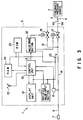
- an apparatus 1 for regulating the pneumatic pressure of a motor vehicle tire 1 is connected by means of a coupler 4 to the proximal end of a pressure supply hose 3, which is by turn connected to a pneumatic pressure source 2.
- the apparatus 1 comprises a pneumatic pressure regulating unit 5 designed to receive at a side thereof a coupling nipple 4a of said coupler 4 to connect itself to a corresponding end of said coupler 4, a linkage hose 6 made of pressure-resistant rubber and arranged on a side of the pneumatic pressure regulating unit 5 opposite to the side for receiving said coupling nipple 4a and a tire valve connecting section 7 fitted to the distal end of said linkage hose 6 and located close to said pneumatic pressure regulating unit 5.
- the tire valve connecting section 7 is always held open and, once connected to the tire valve 9 of a motor vehicle tire 8 by the operator of the apparatus 1, renders the tire valve 9 open so that the inside of the motor vehicle tire 8 comes to communicate with the inside of the pneumatic pressure regulating unit 5. More specifically, the coupling nipple 4a is fitted to an end of the air inlet pipe 6a connected to the corresponding side of said pneumatic pressure regulating unit 5.
- the pneumatic pressure regulating unit 5 comprises a specified value input section 11 having value specifying buttons 10 arranged on the upper surface thereof and a display unit 13 having a display window 12 provided with digital display members 12a, 12b for displaying the difference of a measured pneumatic pressure value and a specified pneumatic pressure value (which will be described hereinafter) of the motor vehicle tire 8.
- a passageway 14 is formed within the pneumatic pressure regulating unit 5 to hold the pressure supply hose 3 in communication with the linkage hose 6 and provided with a pressure sensor 15 that determines the actual pneumatic pressure of the tire 8 by measuring the pneumatic pressure in the passageway 14.
- the passageway 14 has a branch way 16 diverging from the passageway 14 at a point located closer to the pneumatic pressure source 2 than the pressure sensor 15 and is provided with an air charging valve 17 at a point located closer to the pneumatic pressure source 2 than the point of divergence of the branch way 16, said air charging valve 17 being controlled for the extent of openness.
- Said branch way 16 by turn is provided with an air discharging valve 18, which is controlled for the extent of openness.
- Said air charging valve 17 and air discharging valve 18 are connected to a valve drive section 20 that selectively drives said valve 17 or 18 to open or close in a controlled manner and regulates the extent of openness of said valve 17 or 18 in accordance with control signal A transmitted from a control unit 19, which will be described hereinafter.
- the control unit 19 typically comprises one or more than one microprocessors and connected to said specified value input section 11, display unit 13, valve drive section 20 and pressure sensor 15 as well as to a buzzer 22, a RAM 24 and a ROM 25.
- Said specified value input section 11, display unit 13, control unit 19, valve drive section 20, buzzer 22, RAM 24 and ROM 25 are connected to a battery 23 that supplies power to these components.
- Said battery 23 is provided with an ON/OFF power switch (not shown).
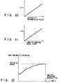
- Said ROM 25 stores a control program as illustrated in the flow charts of Figs. 4 through 7B, which will be described hereinafter, along with map data including those for a graph showing a typical relationship between the absolute value of the pressure difference ⁇ P between the specified pneumatic pressure level and the measured pneumatic pressure level of a motor vehicle tire and the extent of openness of a valve of the first embodiment at the time of the initial specification of a pneumatic pressure level as illustrated in Fig. 10 and a graph showing a typical relationship between the absolute value of the difference ⁇ P between the specified pneumatic pressure level and the measured pneumatic pressure level of a motor vehicle tire and the duration of time of keeping a valve of the first embodiment open at the time of the initial specification of a pneumatic pressure level as illustrated in Fig. 11.
- the operator Before starting an operation of regulating the pneumatic pressure of a tire 8, the operator specifies a mode of operation, using appropriate ones of the value specifying buttons 10 of the specified value input section 11, in order to define some of the basic parameters for the operation, including the unit of pneumatic pressure, the sequence according to which the tires of a motor vehicle are handled for pneumatic pressure regulation (typically selected from five alternative sequences of (1) F ⁇ F ⁇ R ⁇ R, (2) F ⁇ R ⁇ R ⁇ F, (3) R ⁇ R ⁇ F ⁇ F, (4) R ⁇ F ⁇ F ⁇ R and (5) as defined by the operator on the spot, where F and R stand for a front tire and a rear tire respectively), the time expressed in minutes that needs to pass under the atmospheric pressure before determining the end of operation in [Step S14] as described hereinafter and allowance E for determining the pressure difference ⁇ P which will also be described hereinafter.
- These parameters are stored in the RAM 24 even after the power switch is turned off so that the same parameters are selected when the switch is turned on next time.
- the specified value input section 11 transmits a digital signal representing the specified pneumatic pressure value to the control unit 19. After entering the pneumatic pressure value, the operator connects the tire valve connecting section 7 to the tire valve 9 of an appropriate wheel tire 8.
- control unit 19 Upon receiving the digital signal for the specified value, the control unit 19 has the display window 12 of the display unit 13 digitally display the specified value.
- the control unit 19 also writes the specified value in the RAM 24.
- a pneumatic pressure value for the front wheel tires 8 by depressing one or more than one selected value specifying buttons 10, a digital signal representing the specified value is transmitted to the control unit 19.
- control unit 19 Upon receiving the digital signal for the front wheel tires, the control unit 19 has the display window 12 of the display unit 13 digitally display the value specified for the front wheel tires.
- the control unit 19 also writes the value specified for the front wheel tires in the RAM 24.
- a pneumatic pressure value for the rear wheel tires 8 As the operator specifies a pneumatic pressure value for the rear wheel tires 8 by depressing one or more than one selected value specifying buttons 10, a digital signal representing the specified value is transmitted to the control unit 19. After entering the pneumatic pressure value, the operator connects the tire valve connecting section 7 to the tire valve 9 of one of the rear wheel tires 8.
- control unit 19 Upon receiving the digital signal for the rear wheel tires, the control unit 19 has the display window 12 of the display unit 13 digitally display the value specified for the rear wheel tires.
- the control unit 19 also writes the value specified for the rear wheel tires in the RAM 24.
- control unit 19 transmits a signal specifying a tire (a front wheel tire or a rear wheel tire) 8 and a corresponding digital signal representing the specified pneumatic pressure value for the tire to the display unit 13, which by turn displays the specified tire and the specified pneumatic pressure value.
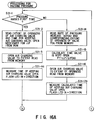
- the specified tire needs to be the first one in the sequence defined in [Step S1].
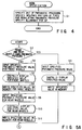
- control unit 19 determines if the specified pneumatic pressure is equal to the atmospheric pressure or not and the operation proceeds to [Step S14] if the answer to this question is positive, whereas it proceeds to [Step S15] if the answer is negative.
- the control unit 19 determines if the time defined in [Step S1] has passed under the atmospheric pressure. If the answer to this question positive, the control unit 19 terminates the operation of regulating the pneumatic pressure of the tire. If not, it returns to [Step S13] and follows a loop linking [Step S13] and [Step S14] until the answer becomes positive.
- the control unit 19 measures the stand-by time required for the signal from the pressure sensor 15 to become stabilized. This is a step of operation provided to cancel any measurement of the pneumatic pressure of the selected tire until the pressure comes to show a steady value in view of the fact that the pneumatic pressure of a tire may fluctuate immediately after it is raised in [Step S21] or reduced in [Step S22] as will be described hereinafter.
- control unit 19 Upon receiving a signal representing a measured pneumatic pressure of the tire 8 from the pressure sensor 15, the control unit 19 performs an arithmetic operation to calculate the actual pneumatic pressure of the tire 8.
- control unit 19 determines the pressure difference ⁇ P between the measured value P m and the specified value P pr for the pneumatic pressure of the tire 8, using the equation below.
- ⁇ P P m - P pr
- the control unit 19 transmits a digital signal representing the result of the above calculation, or ⁇ P, to the display unit 13 and has it display the digital value of ⁇ P and the specified pneumatic pressure value. More specifically, the control unit 19 has the digital display members 12a and 12b respectively display the specified pneumatic pressure and the pressure difference ⁇ P.
- the control unit 19 transmits a drive signal to the buzzer 22 to have the latter sound to inform the operator that the operation of regulating the pneumatic pressure of the tire is now over. Then, the control unit 19 returns to [Step S12].
- control unit 19 carries out a processing for raising the pressure of the tire 8 following the flow chart of Figs. 6A and 6B (which will be described hereinafter) and then returns to [Step S13].
- the control unit 19 carries out a processing for reducing the pressure of the tire 8 following the flow chart of Figs. 7A and 7B (which will be described hereinafter) and then returns to [Step S13].
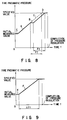
- a processing for raising the pneumatic pressure of a tire 8 to be carried out by following the flow chart of Figs. 6A and 6B will be described by referring to Figs. 6A, 6B and 8 that illustrates the relationship between the pneumatic pressure of a tire 8 and the time consumed for the operation of regulating the pressure of the tire 8.
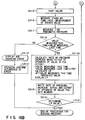
- the control unit 19 determines if the processing for raising the pneumatic pressure is to be carried out for the first time in the current operation or not. If the answer to this question is positive, then the operation proceeds to [Step S21-2]. Otherwise, the operation goes to [Step S21-14].
- the control unit 19 reads the extent of openness of the air charging valve F OA and the time for keeping the air charging valve open F OT corresponding to the pressure difference ⁇ P and stored in advance in the ROM 25.
- the relationship between ⁇ P and the extent of openness of the air charging valve 17 and the relationship between ⁇ P and the time for keeping the air charging valve open as stored in the ROM 25 will be typically like the graphs respectively illustrated in Figs. 10 and 11. If summarily stated, the greater the absolute value of ⁇ P, the greater the extent of openness of the air charging valve and the time for keeping the air charging valve open. Conversely, the smaller the absolute value of ⁇ P, the smaller the extent of openness of the air charging valve and the time for keeping the air charging valve open.
- Each of the extent of openness of the air charging valve and the time for keeping the air charging valve open is linearly proportional to ⁇ P.
- the control unit 19 transmits a control signal representing the extent of openness of the air charging valve F OA it has read from the ROM 25 to the valve drive section 20, which transmits a drive signal for controlling the openness of the air charging valve to the air charging valve 17 in response to the control signal so that the extent of openness of the air charging valve 17 correctly corresponds to the pressure difference ⁇ P.
- the control unit 19 measures the time of keeping the air charging valve 17 F OT open as a function of the pressure difference ⁇ P.
- the control unit 19 stops transmitting the control signal so that the valve drive section 20 stops sending the drive signal to close the air charging valve 17.
- the tire 8 is charged with air coming from the pneumatic pressure source 2 at an rate and to an extent as indicated by line A in Fig. 8.
- the control unit 19 measures the stand-by time required of it until a steady value is measured for the signal representing the pneumatic pressure measured by the pressure sensor 15. This is a step of operation provided to cancel any measurement of the pneumatic pressure of the selected tire until the pressure comes to show a steady value in view of the fact that the pneumatic pressure of a tire may fluctuate immediately after it is raised. (This stand-by time corresponds to line B in Fig. 8.)
- the control unit 19 determines if the measured pneumatic pressure value obtained this time is greater than the corresponding value obtained last time. If the answer to this question is positive, it decides that the operation of regulating the pneumatic pressure of the tire is proceeding properly and the operation proceeds to [Step S21-9]. If the answer is negative, it decides that there is something wrong with the operation and jumps to [Step S21-12].
- control unit 19 writes the rate of pressure change a(FOA) and the extent of openness of the valve F OA obtained by the above calculations in the RAM 24.
- control unit 19 regards that there is something wrong with the operation of charging the tire with air, it transmits an error signal to the display unit 13 and has it display an air charging error sign.
- the operator confirms that an error has occurred in the operation of charging the tire with air.
- Step S21-1 If it is determined in the above [Step S21-1] that the processing for raising the pneumatic pressure to be carried out is not the first one in the current operation, the control unit 19 reads from the RAM 24 the rate of pressure change a(FOA) and the extent of openness of the valve F OA written in the RAM 24 in [Step S21-10].
- the control unit 19 then calculates the time for keeping the valve open F T from the rate of pressure change a(FOA) and the pressure difference ⁇ P, using the formula below.
- F T ⁇ P/a(FOA)
- the control unit 19 transmits a control signal representing the extent of openness of the air charging valve F OA it has read from the RAM 24 to the valve drive section 20, which transmits a drive signal for controlling the openness of the air charging valve to the air charging valve 17 in response to the control signal so that the air charging valve 17 shows an extent of openness of the air charging valve 17 F OA same as that of the last processing.
- the control unit 19 measures the time of keeping the air charging valve 17 open until the latter becomes equal to the time for keeping the air charging valve 17 F T as calculated in [Step S21-15].
- line D in Fig. 8 corresponds to line D in Fig. 8, where line D is obtained by firstly drawing line C having a gradient (rate of pressure change) equal to line A until the specified pneumatic pressure value is reached and then shifting line C to the right by an amount corresponding to the length of line B representing the stand-by time before a steady value is measured for the pneumatic pressure of the tire.
- Line E in Fig. 8 corresponds to the stand-by time required for the signal from the pressure sensor 15 to become stabilized in the initial measurement in [Step S15].
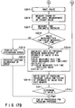
- the control unit 19 determines if the processing for reducing the pneumatic pressure is to be carried out for the first time in the current operation or not. If the answer to this question is positive. then the operation proceeds to [Step S22-2]. Otherwise, the operation goes to [Step S22-14].
- the control unit 19 reads the extent of openness of the air discharging valve R OA and the time for keeping the air discharging valve open R OT corresponding to the pressure difference ⁇ P and stored in advance in the ROM 25.
- the relationship between ⁇ P and the extent of openness of the air discharging valve 18 and the relationship between ⁇ P and the time for keeping the air discharging valve open as stored in the ROM25 will be typically like the graphs respectively illustrated in Figs. 10 and 11 as in the case of an processing for raising the tire pressure. If summarily stated, the greater the absolute value of ⁇ P, the greater the extent of openness of the air discharging valve and the time for keeping the air discharging valve open.
- the control unit 19 transmits a control signal representing the extent of openness of the air discharging valve R OA it has read from the ROM 25 to the valve drive section 20, which transmits a drive signal for controlling the openness of the air discharging valve to the air discharging valve 18 in response to the control signal so that extent of openness of the air discharging valve 18 correctly corresponds to the pressure difference ⁇ P.
- the control unit 19 measures the time of keeping the air discharging valve 18 R OT open as a function of the pressure difference ⁇ P.
- the control unit 19 stop transmitting the control signal so that the valve drive section 20 stops sending the drive signal to close the air discharging valve 18. Now, the air in the tire 8 is partly discharged into the atmosphere.
- control unit 19 measures the stand by time required of it until a steady value is measured for the signal representing the pneumatic pressure measured by the pressure sensor 15. This is a step of operation provided to cancel any measurement of the pneumatic pressure of the selected tire until the pressure comes to show a steady value in view of the fact that the pneumatic pressure of a tire may fluctuate immediately after it is reduced.
- the control unit 19 determined if the measured pneumatic pressure value obtained this time is smaller than the corresponding value obtained last time. If the answer to this question is positive, it decides that the operation of regulating the pneumatic pressure of the tire is proceeding properly and the operation proceeds to [Step S22-9]. If the answer is negative, it decides that there is something wrong with the operation and jumps to [Step S22-12].
- control unit 19 writes the rate of pressure change a(ROA) and the extent of openness of the valve R OA obtained by the above calculations in the RAM 24.
- control unit 19 regards that there is something wrong with the operation of discharging the tire with air, it transmits an error signal to the display unit 13 and has it display an air discharging error sign.
- the operator confirms that an error has occurred in the operation of discharging air from the tire.
- Step S22-1 If it is determined in the above [Step S22-1] that the processing for reducing the pneumatic pressure to be carried out is not the first one in the current operation, the control unit 19 reads from the RAM 24 the rate of pressure change a(ROA) and the extent of openness of the valve R OA written in the RAM 24 in [Step S22-10].
- the control unit 19 calculates the time for keeping the valve open R T from the rate of pressure change a(ROA) and the pressure difference ⁇ P, using the formula below.
- R T ⁇ P/a(ROA)
- the control unit 19 transmits a control signal representing the extent of openness of the air discharging valve R OA it has read from the RAM 24 to the valve drive section 20, which transmits a drive signal for controlling the openness of the air discharging valve to the air discharging valve 18 in response to the control signal so that the air discharging valve 18 shows an extent of openness of the air discharging valve 18 R OA same as that of the last processing.
- the control unit 19 measures the time of keeping the air discharging valve 18 open until the latter becomes equal to the time for keeping the air discharging valve 18 R T as calculated in [Step S22-15].
- a specified pneumatic pressure value is given to it by way of the specified value input section 11, it causes the pressure sensor 15 to actually measure the pneumatic pressure of a specific tire and then calculates the pressure difference between the actual pneumatic pressure of the tire measured by the pressure sensor 15 and the specified pneumatic pressure. It then charges the tire with air or discharges air from the tire, controlling the extent of openness of the air charging valve 17 or the air discharging valve 18 and the time for keeping the air charging valve 17 or the air discharging valve 18 open, whichever appropriate, by sending a control signal to the valve control section 20 as a function of the calculated pressure difference. Thereafter, the control unit 19 calculates the rate of pressure change from the actual pneumatic pressure value measured for the second time as well as the pressure difference between said actual pneumatic pressure value measured for the second time and the specified pneumatic pressure.
- valve control section 20 It then charges the tire with air or discharges air from the tire by sending another control signal to the valve control section 20 as a function of the newly obtained pressure difference.
- the time for keeping the air charging valve 17 or air discharging valve 18 is open is varied, but the extent of openness of valve 17 or 18 is maintained at the initial value.
- the operation of charging a tire 8 with air or discharging a tire 8 of air is carried out by calculating the actual rate of pressure change in the tire 8 (that may vary from tire to tire) and using it to determine the time for keeping the valve open for the next time.
- the control unit 19 goes to [Step S12] after completing the operation of regulating the pneumatic pressure of the preceding tire 8 and starts with [Step S21-14] for the pressure raising processing in [Step S21] or [Step S22-14] for the pressure reducing processing in [Step S22], whichever appropriate.
- control unit 19 calculates the pressure difference between the specified pneumatic pressure value given to it by way of the specified value input section 11 and the actual pneumatic pressure level measured by the pressure sensor 15 each time the actual pneumatic pressure is measured since the second time of measurement, the extent of openness of the air charging valve 17 or the air discharging valve 18, whichever appropriate, may always be held to the initial value so that only the time for keeping the valve open ⁇ t1 needs to be calculated each time from pressure difference ⁇ P and the rate of pressure change (the gradient of line F in Fig. 9) obtained for the preceding tire 8 as illustrated in Fig. 9.
- the actual rate of pressure change obtained for the preceding tire 8 during the operation of charging it with air or discharging air from it is utilized to determine the time for keeping the air charging or discharging valve open for the succeeding tire 8.
- the fact that the pneumatic pressure regulating unit 5 is arranged in the proximity of the tire valve connecting section 7 and, therefore, the operator is not required to move around on the floor to perform the assignment will further improve the efficiency with which the operator carries out the work of regulating the pneumatic pressure of the tires of a motor vehicle including entering, if any, newly specified pneumatic pressure values into the apparatus.
- the operator can visually confirm the specified value to avoid any error in specifying a pneumatic pressure value. Still additionally, since the pressure difference ⁇ P between the specified pneumatic pressure and the actual pneumatic pressure measured by the pressure sensor 15 is displayed on the digital display member 12b along with the specified pneumatic pressure each time the pneumatic pressure is measured, the operator will never fail to recognize that there is a pressure difference, if any, and the operation of regulating the pneumatic pressure of the tires of a motor vehicle is still going on.
- the buzzer 22 of the embodiment is so designed that it sounds whenever the operation of regulating the pneumatic pressure of the tires of a motor vehicle is completed, the operator can easily recognize the end of a pneumatic pressure regulating operation.
- tire valve connecting section 7 of the above first embodiment is constantly held open, it may alternatively be kept closed.
- the relationship between the pressure difference ⁇ P and the extent of openness of the air charging or discharging valve and the relationship between ⁇ P and the time for keeping the valve open may not necessarily be restricted to those of the above embodiment and they may be appropriately modified.
- the relationships as illustrated in Figs. 29 and 30 through 34 may take place when simply structured valves that can only be opened or closed (ON-OFF valves) are used for the air charging and discharging valves. The mode of operation for controlling these ON-OFF valves in an apparatus according to the invention will be described hereinafter.
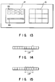
- the display window 12 comprises a digital display member 12a for displaying a specified pneumatic pressure value and a plurality of light emitting elements (LEDs) 12c arranged below the display member 12a in Fig. 13.
- LEDs light emitting elements
- the light emitting elements 12c may be utilized in such a manner that the pressure difference ⁇ P between the specified pneumatic pressure value and the actual pneumatic pressure value measured by the pressure sensor 15 is indicated by the number of LEDs.
- One LED may be activated as illustrated in Fig. 14 or, numbers of LEDs may be activated as illustrated in Fig. 15.
- the LEDs flash to inform the operator of the fact that the apparatus is carrying out a pressure raising or reducing operation.
- control unit 19 of the second embodiment will be described only for the portions that are different from those of the first embodiment.
- Fig. 16A is a portion of a flow chart for a pressure raising processing corresponding to that of Fig. 6A for the first embodiment. Note that [Step S21-4], [Step 21-17] in Fig. 6A is modified to become [Step S21-4a], [Step 21-17a] in Fig. 16A, respectively.
- the control unit 19 measures the time of keeping the air charging valve 17 F OT open as a function of the pressure difference ⁇ P.
- Figs. 18A through 18E illustrates light emitting elements 12c flashing in the - direction, they flash in the opposite direction or in the + direction in this step.
- the control unit 19 measures the time of keeping the air charging valve 17 open until the latter becomes equal to the time for keeping the air charging valve 17 F T as calculated in [Step S21-15].
- Fig. 16B is the remaining portion of the flow chart for a pressure raising processing corresponding to that of Fig. 6B for the first embodiment. Note that [Step S21-9] in Fig. 6B is modified to become [Step S21-9a] in Fig. 16B.
- Fig. 17A is a portion of a flow chart for a pressure reducing processing corresponding to that of Fig. 7A for the first embodiment. Note that [Step S22-4], [Step S22-17] in Fig. 7A is modified to become [Step S22-4a], [Step S22-17a] in Fig. 17A, respectively.
- the control unit 19 measures the time of keeping the air discharging valve 18 R OT open as a function of the pressure difference ⁇ P.
- FIG. 18A through 18E illustrates light emitting elements 12c flashing in the - direction.
- the control unit 19 measures the time of keeping the air discharging valve 18 open until the latter becomes equal to the time for keeping the air discharging valve 18 R T calculated in [step S22-15].
- Fig. 17B is the remaining portion of the flow chart for a pressure reducing processing corresponding to that of Fig. 7B for the first embodiment. Note that [Step S22-9] in Fig. 7B is modified to become [Step S22-9a] in Fig. 17B.
- the way of flashing the light emitting elements 12c while calculating the time for keeping the valve open may be modified to appear as those in Figs. 19A through 19J.
- FIG. 20 through 28 This embodiment differs from the first embodiment only in that the processing operation of the control unit 19 of the first embodiment as illustrated in the flow charts of Figs. 4 through 7B are replaced by those of Figs. 20 through 23.
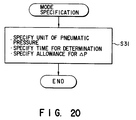
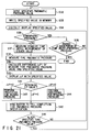
- the operator Before starting an operation of regulating the pneumatic pressure of a tire 8, the operator specifies a mode of operation, using appropriate ones of the value specifying buttons 10 of the specified value input section 11, in order to define some of the basic parameters for the operation, including the unit of pneumatic pressure, the time expressed in minutes that needs to pass under the atmospheric pressure before determining the end of operation in [Step S36] as described hereinafter and allowance E for determining the pressure difference ⁇ P which will also be described hereinafter. These parameters are stored in the memory even after the power switch is turned off so that the same parameters are selected when the switch is turned on next time.
- the specified value input section 11 transmits a digital signal representing the specified pneumatic pressure value to the control unit 19.
- the operator connects the tire valve connecting section 7 to the tire valve 9 of the wheel tire 8. If the pneumatic pressure of a tire to be handled after the above tire 8 is different from the above specified value, the operator restarts from this step before connecting the tire valve connecting section 7 to the tire valve 9 of the tire.
- control unit 19 Upon receiving the digital signal for the specified value, the control unit 19 writes the specified value in the RAM 24.
- the control unit 19 also has the digital display member 12a of the digital window 12 of the display unit 13 digitally display the specified value.
- control unit 19 determines if the specified pneumatic pressure is equal to the atmospheric pressure or not and the operation proceeds to [Step S36] if the answer to this question is positive, whereas it proceeds to [Step S37] if the answer is negative. If the pneumatic pressure of a tire to be handled after the above tire 8 is same as the above specified value, the operator restarts from this step before connecting the tire valve connecting section 7 to the tire valve 9 of the tire.
- the control unit 19 determines if the time defined in [Step S31] has passed under the atmospheric pressure. If the answer to this question positive, the control unit 19 terminates the operation of regulating the pneumatic pressure of the tire. If not, it returns to [Step S35 and follows a loop linking [Step S35] and [Step S36] until the answer becomes positive.
- the control unit 19 measures the stand-by time required for the signal from the pressure sensor 15 to become stabilized. This is a step of operation provided to cancel any measurement of the pneumatic pressure of the selected tire until the pressure comes to show a steady value in view of the fact that the pneumatic pressure of a tire may fluctuate immediately after it is raised in [Step S33] or reduced in [Step S34] as will be described hereinafter.
- control unit 19 Upon receiving a signal representing a measured pneumatic pressure of the tire 8 from the pressure sensor 15, the control unit 19 performs an arithmetic operation to calculate the actual pneumatic pressure of the tire 8.
- control unit 19 determines the pressure difference ⁇ P between the measured value P m and the specified value P pr for the pneumatic pressure of the tire 8, using the equation below.
- ⁇ P Pm - Ppr
- the control unit 19 transmits a digital signal representing the result of the above calculation, or ⁇ P, to the display unit 13 and has the digital display member 12b display the digital value of ⁇ P and the specified pneumatic pressure value.
- the control unit 19 transmits a drive signal to the buzzer 22 to have the latter sound.
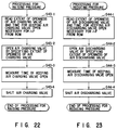
- control unit 19 carries out a processing for raising the pressure of the tire 8 following the flow chart of Fig. 22 (which will be described hereinafter) and then returns to [Step S37].
- the control unit 19 carries out a processing for reducing the pressure of the tire 8 following the flow chart of Fig. 23 (which will be described hereinafter) and then returns to [Step S37].
- control unit 19 reads the extent of openness of the valve and the time for keeping the valve open stored in the ROM 25 in advance.
- the control unit 19 transmits a control signal representing the extent of openness of the valve it has read from the ROM to the valve drive section 20, which transmits a drive signal for controlling the openness of the valve to the air charging valve 17 in response to the control signal so that the extent of openness of the air charging valve 17 correctly corresponds to the pressure difference ⁇ P.
- the control unit 19 measures the time of keeping the valve 17 open as a function of the pressure difference ⁇ P.
- the control unit 19 stops transmitting the control signal so that the valve drive section 20 stops sending the drive signal to close the air charging valve 17.
- the tire 8 is charged with air coming from the pneumatic pressure source 2 at a rate corresponding to the specified openness of the valve and for the specified time for keeping the valve open.
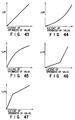
- the relationship between the pressure difference ⁇ P and the extent of openness of the air charging valve 17 and the relationship between ⁇ P and the time for keeping the air charging valve open as stored in the ROM 25 will be typically like the graphs respectively illustrated in Figs. 24 and 25. If summarily stated, the greater the absolute value of ⁇ P, the greater the extent of openness of the air charging valve and the time for keeping the air charging valve open. Conversely, the smaller the absolute value of ⁇ P, the smaller the extent of openness of the air charging valve and the time for keeping the air charging valve open. Each of the extent of openness of the air charging valve and the time for keeping the air charging vale open is linearly proportional to ⁇ P.
- control unit 19 reads the extent of openness of the valve and the time for keeping the valve open stored in the ROM 25 in advance.
- the control unit 19 transmits a control signal representing the extent of openness of the valve it has read from the ROM 25 to the valve drive section 20, which transmits a drive signal for controlling the openness of the valve to the air discharging valve 18 in response to the control signal so that the extent of openness of the air discharging valve 18 correctly corresponds to the pressure difference ⁇ P.
- the control unit 19 measures the time of keeping the valve 18 open as a function of the pressure difference ⁇ P.
- the control unit 19 stops transmitting the control signal so that the valve drive section 20 stops sending the drive signal to close the air discharging valve 18. Now, the tire 8 is partly discharged of air at a rate corresponding to the specified openness of the valve and for the specified time for keeping the valve open.
- the relationship between the pressure difference ⁇ P and the extent of openness of the air discharging valve 18 and the relationship between ⁇ P and the time for keeping the air discharging valve 18 open as stored in the ROM 25 will be typically like the graphs respectively illustrated in Figs. 24 and 25. If summarily stated, the greater the absolute value of ⁇ P, the greater the extent of openness of the air discharging valve and the time for keeping the air discharging valve open. Conversely, the smaller the absolute value of ⁇ P, the smaller the extent of openness of the air discharging valve 18 and the time for keeping the air discharging valve 18 open. Each of the extent of openness of the air discharging valve 18 and the time for keeping the air discharging vale open is linearly proportional to ⁇ P.
- Fig. 26 is a timing chart for measuring the pneumatic pressure of a tire and operating the air charging valve 17 or the air discharging valve 18 when the operation of charging a tire with air or discharging air from a tire is carried out following the appropriate ones of the flow charts of Figs. 21 through 23.
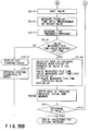
- the pneumatic pressure is measured for the first time in [Step S38] (A in Fig. 26) and then a processing for raising or reducing pressure is carried out as a function of ⁇ P in [Step S43] or [Step S44] respectively (B in Fig. 26).
- the stand-by time required for the signal from the pressure sensor to become stabilized is measured (C in Fig. 26) and, thereafter, the above procedures are repeated. Since the absolute value of ⁇ P decreases each time a pressure raising or reducing processing is carried out, the time for keeping the valve open will be shortened gradually and the operation of regulating the pneumatic pressure will become a fine tuning operation.
- the pressure sensor 15 measures the actual pneumatic pressure of a tire 8 and the control unit 19 calculates the pressure difference ⁇ P between the measured pneumatic pressure of the tire 8 and the specified value and controls the extent of openness of the air charging valve 17 or the air discharging valve 18 and the time for keeping the valve open as a function of ⁇ P until the pneumatic pressure of the tire 8 reaches the specified level.
- the fact that the pneumatic pressure regulating unit 5 is arranged in the proximity of the tire valve connecting section 7 and, therefore, the operator is not required to move around on the floor to perform the assignment will further improve the efficiency with which the operator carries out the work of regulating the pneumatic pressure of the tires of a motor vehicle including entering, if any, newly specified pneumatic pressure values into the apparatus.
- the operator can visually confirm the specified value to avoid any error in specifying a pneumatic pressure value. Still additionally, since the pressure difference ⁇ P between the specified pneumatic pressure and the actual pneumatic pressure measured by the pressure sensor 15 is displayed on the digital display member 12b along with the specified pneumatic pressure each time the pneumatic pressure is measured, the operator will never fail to recognize that there is a pressure difference, if any, and the operation of regulating the pneumatic pressure of the tires of a motor vehicle is still going on.
- the buzzer 22 of the embodiment is so designed that it sounds whenever the operation of regulating the pneumatic pressure of the tires of a motor vehicle is completed, the operator can easily recognize the end of a pneumatic pressure regulating operation.
- tire valve connecting section 7 of the above third embodiment is constantly held open, it may alternatively be kept closed.
- the relationship between the pressure difference ⁇ P and the extent of openness of the air charging or discharging valve and the relationship between ⁇ P and the time for keeping the valve open may not necessarily be restricted to those of the above embodiment and they may be appropriately modified.
- the relationships as illustrated in Figs. 29 and 30 trough 34 may take place when simply structured valves that can only be opened or closed (ON-OFF valves) are used for the air charging and discharging valves.
- the display window 12 comprises a digital display member 12a for displaying a specified pneumatic pressure value and a plurality of light emitting elements (LEDs) arranged in a row below the display member 12a as illustrated in Fig. 13.
- LEDs light emitting elements
- the light emitting elements 12c may be utilized in such a manner that the pressure difference ⁇ P between the specified pneumatic pressure value and the actual pneumatic pressure value measured by the pressure sensor 15 is indicated by the number of LEDs.
- One LED may be activated as illustrated in Fig. 14 or, numbers of LEDs may be activated as illustrated in Fig. 15.
- the LEDs flash to inform the operator of the fact that the apparatus is carrying out a pressuring raising or reducing operation.
- the fourth embodiment differs from the above third embodiment only in part of the operation of the control unit 19 for controlling the display unit, only the portions that are different from the third embodiment will be described below and the description for the remaining portions will be omitted.
- Fig. 27 is a flow chart for a pressure raising processing corresponding to that of Fig. 22 of the third embodiment. Note that [Step S43-3] of Fig. 22 is modified to make [Step 43-3a] in Fig. 27.
- the control unit 19 measures the time of keeping the air charging valve 17 open as a function of the pressure difference ⁇ P.
- Figs. 18A through 18E illustrates light emitting elements 12c flashing in the - direction, they flash in the opposite direction or in the + direction in this step.
- Fig. 28 is a flow chart for a pressure reducing processing corresponding to that of Fig. 23 for the third embodiment. Note that [Step S44-3] in Fig. 23 is modified to make [Step S44-3a] in Fig. 28.
- the control unit 19 measures the time of keeping the air discharging valve 18 open as a function of the pressure difference ⁇ P.
- the way of flashing the light emitting elements 12c while calculating the time for keeping the valve open may be modified to appear as those in Figs. 19A through 19J.
- the ROM 25 stores map data including those for a graph showing a typical relationship between the pressure difference ⁇ P and the extent of openness of a valve as illustrated in Fig. 10 and a relationship between ⁇ P and the time for keeping the valve open as shown in Fig. 11 in the above described first through fourth embodiments
- the ROM 25 may only store map data concerning the relationship between ⁇ P and the time for keeping a valve open typically as illustrated in Figs. 30 through 34 if simply structured valves that can only be opened or closed (ON-OFF valves) are used for the air charging and discharging valves.
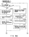
- a fifth embodiment of the invention will be described by referring to Figs. 35A, 35B, 36A, 36B.
- [Step S21-2], [Step S21-3], [Step S21-14], [Step S21-16] of Fig. 6A and [Step S22-2], [Step S22-3], [Step S22-4], [Step S22-14], [Step S22-16] of Fig. 7A for the first embodiment are respectively modified to make [Step S21-2a], [Step S21-3a], [Step S21-14a], [Step S21-16a] in Fig.
- control unit 19 reads the time F OT for keeping the air charging valve open corresponding to the pressure difference ⁇ P and stored in advance in the ROM 25.
- the valve drive section 20 opens the air charging valve 17.
- the control unit 19 writes the rate of pressure change of a(FOA) in the RAM 24.
- Step S21-1 If it is determined in the above [Step S21-1] that the processing for raising the pneumatic pressure to be carried out is not the first one in the current operation, the control unit 19 reads the rate of pressure change a(FOA) from the RAM 24.
- the valve drive section 20 opens the air charging valve 17.
- control unit 19 reads the time R OT for keeping the air discharging valve open corresponding to the pressure difference ⁇ P and stored in advance in the ROM 25.
- the valve drive section 20 opens the air discharging valve 18.
- the control unit 19 writes the rate of pressure change a(ROA) in the RAM 24.
- Step S22-1 If it is determined in the above [Step S22-1] that the processing for reducing the pneumatic pressure to be carried out is not the first one in the current operation, the control unit 19 reads the rate of pressure change a(ROA) from the RAM 24.
- the valve drive section 20 opens the air discharging valve 18.
- control unit 19 reads the time F OT for keeping the air charging valve open corresponding to the pressure difference ⁇ P and stored in advance in the ROM 25.
- the valve drive section 20 opens the air charging valve 17.
- Step S21-1 If it is determined in the above [Step S21-1] that the processing for raising the pneumatic pressure to be carried out is not the first one in the current operation, the control unit 19 reads the rate of pressure change a(FOA) from the RAM 24.
- the valve drive section 20 opens the air charging valve 17.
- control unit 19 reads the time R OT for keeping the air discharging valve open corresponding to the pressure difference ⁇ P and stored in advance in the ROM 25.
- the valve drive section 20 opens the air discharging valve 18.
- Step S22-1 If it is determined in the above [Step S22-1] that the processing for reducing the pneumatic pressure to be carried out is not the first one in the current operation, the control unit 19 reads the rate of pressure charge a(ROA) from the RAM 24.
- the valve drive section 20 opens the air discharging valve 18.
- control unit 19 reads the time F OT for keeping the air charging valve open corresponding to the pressure difference ⁇ P and stored in advance in the ROM 25.
- the valve drive section 20 opens the air charging valve 17.
- control unit 19 reads the time R OT for keeping the air discharging valve open corresponding to the pressure difference ⁇ P and stored in advance in the ROM 25.
- the valve drive section 20 opens the air discharging valve 18.
- the ROM 25 stores map data including those for a graph showing a typical relationship between the pressure difference ⁇ P and the extent of openness of a valve as illustrated in Fig. 10 and a relationship between ⁇ P and the time for keeping the valve open as shown in Fig. 11 in the above described first through fourth embodiments
- the ROM 25 may only store map data concerning the relationship between ⁇ P and the extent of openness of a valve typically as illustrated in Figs. 43 through 47 if simply structured valves that can only be opened for a predetermined period of time and is capable of being controlled for the extent of openness are used for the air charging and discharging valves according to ninth and tenth embodiments described later.
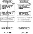
- control unit 19 reads the extent of openness of the air charging valve corresponding to the pressure difference ⁇ P and stored in advance in the ROM 25.
- the valve drive section 20 keeps the air charging valve 17 open for a predetermined time.
- control unit 19 reads the extent of openness of the air discharging valve open corresponding to the pressure difference ⁇ P and stored in advance in the ROM 25.
- the valve drive section 20 keeps the air discharge valve 18 open for a predetermined time.
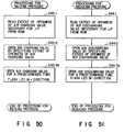
- control unit 19 reads the extent of openness of the air charging valve corresponding to the pressure difference ⁇ P and stored in advance in the ROM.
- the valve drive section 20 keeps the air charging valve 17 open for a predetermined time, the control unit 19 flashes the light emitting elements 12c in the + direction.
- control unit 19 reads the extent of openness of the air discharging valve open corresponding to the pressure difference ⁇ P and stored in advance in the ROM 25.
- the valve drive section 20 keeps the air discharging valve 18 open for a predetermined time.
- the control unit 19 flashes the light emitting elements 12c in the - direction.
- the display window 12 as illustrated in Fig. 13 may be modified to make a one as shown in Fig. 52, where an analog meter 12d is arranged below the digital display member 12a and the pressure difference is indicated by the analog meter 12d.
Landscapes
- Engineering & Computer Science (AREA)
- Mechanical Engineering (AREA)
- Measuring Fluid Pressure (AREA)
- Vehicle Cleaning, Maintenance, Repair, Refitting, And Outriggers (AREA)
- Control Of Fluid Pressure (AREA)
Applications Claiming Priority (4)
| Application Number | Priority Date | Filing Date | Title |
|---|---|---|---|
| JP258652/92 | 1992-09-28 | ||
| JP25864992 | 1992-09-28 | ||
| JP25865292 | 1992-09-28 | ||
| JP258649/92 | 1992-09-28 |
Publications (1)
| Publication Number | Publication Date |
|---|---|
| EP0590462A1 true EP0590462A1 (fr) | 1994-04-06 |
Family
ID=26543773
Family Applications (1)
| Application Number | Title | Priority Date | Filing Date |
|---|---|---|---|
| EP93115103A Ceased EP0590462A1 (fr) | 1992-09-28 | 1993-09-20 | Appareil pour réguler la pression d'un pneumatique d'un véhicule automobile |
Country Status (5)
| Country | Link |
|---|---|
| US (1) | US5429166A (fr) |
| EP (1) | EP0590462A1 (fr) |
| KR (1) | KR940006814A (fr) |
| AU (1) | AU667123B2 (fr) |
| CA (1) | CA2106707A1 (fr) |
Cited By (5)
| Publication number | Priority date | Publication date | Assignee | Title |
|---|---|---|---|---|
| WO1996007568A1 (fr) * | 1994-09-09 | 1996-03-14 | Garage Equipment Maintenance Co. Ltd. | Dispositif manuel pour canalisations d'air destine a un appareil de gonflage |
| WO2006095144A1 (fr) * | 2005-03-08 | 2006-09-14 | Pneumatic Components Limited | Gonfleur electronique de pneu de vehicule |
| CN104108380A (zh) * | 2013-04-16 | 2014-10-22 | 珠海三德艺电子有限公司 | 多功能充气装置及其控制方法 |
| IT202000011224A1 (it) * | 2020-05-19 | 2021-11-19 | COMPRESSORI UNIVERSAL srl | Apparecchio per gonfiaggio dotato di controllo remoto |
| DE102021116307A1 (de) | 2021-06-24 | 2022-03-24 | Audi Aktiengesellschaft | Einrichtung zur Einstellung eines Reifeninnendrucks für ein Fahrzeugrad eines Fahrzeugs |
Families Citing this family (26)
| Publication number | Priority date | Publication date | Assignee | Title |
|---|---|---|---|---|
| US5611875A (en) * | 1994-08-30 | 1997-03-18 | Bachhuber; Anthony A. | Automotive tire inflation system |
| US5891277A (en) * | 1994-08-30 | 1999-04-06 | Bachhuber; Anthony A. | Automotive tire inflation system |
| US6067850A (en) * | 1997-07-09 | 2000-05-30 | Lang; Yu | Fast and accurate tire pressure charge controller |
| US6357469B1 (en) * | 1999-11-05 | 2002-03-19 | Meritor Heavy Vehicle Systems, Llc | Tire valve with integrated pressure sensor |
| US6293147B1 (en) | 1999-12-23 | 2001-09-25 | Hunter Engineering Company | Wheel balancer with pressure adjustment |
| DE10140436A1 (de) * | 2001-08-17 | 2003-03-06 | Porsche Ag | Anzeigevorrichtung für den Reifeninnendruck |
| US6666078B1 (en) * | 2001-12-04 | 2003-12-23 | Dana Corporation | Target tire pressure learning method |
| US6868719B1 (en) | 2001-12-04 | 2005-03-22 | Dana Corporation | Tire pressure monitoring method |
| US6604414B1 (en) | 2001-12-04 | 2003-08-12 | Dana Corporation | Supply and tire pressure sensing apparatus and method |
| US6561017B1 (en) | 2001-12-04 | 2003-05-13 | Dana Corporation | Tire inflation method |
| JP2004150978A (ja) * | 2002-10-31 | 2004-05-27 | Piyo:Kk | 空気圧測定器 |
| US7040153B2 (en) * | 2003-12-01 | 2006-05-09 | Intercomp Company | Tire inflation gauge technology |
| MX221601B (en) † | 2004-05-14 | 2004-07-22 | Basf Ag | Functional fluids containing alkylene oxide copolymers having low pulmonary toxicity |
| USD528028S1 (en) * | 2005-03-21 | 2006-09-12 | William Mott | Air pressure gauge mountable onto a valve stem while inflating/deflating a tire |
| US7430900B2 (en) | 2006-04-05 | 2008-10-07 | John Belanger | Inflation system |
| US7789112B1 (en) * | 2006-11-09 | 2010-09-07 | Wise Robert W | Method and system for inflating an inflatable object |
| KR200445014Y1 (ko) * | 2007-10-26 | 2009-06-22 | 내외 코리아(주) | 타이어 공기압 측정용 압력센서 및 이를 구비한 타이어공기압 모니터링 시스템 |
| US8191586B2 (en) * | 2008-04-21 | 2012-06-05 | Lydi, Llc | Automated apparatus and method for tire pressure maintenance |
| US20110297271A1 (en) * | 2010-06-02 | 2011-12-08 | Haak Systems, LLC | handheld controller for filling wine barrels |
| US10086803B2 (en) * | 2013-08-27 | 2018-10-02 | Ford Global Technologies, Llc | Pump with tire fill assist |
| WO2016195997A1 (fr) * | 2015-05-29 | 2016-12-08 | Weatherby Michael T | Système et procédé d'entretien de sac gonflable de gaz de casque automatisé |
| US10657757B2 (en) * | 2015-07-31 | 2020-05-19 | Daniel J. Burrows | Hybrid air machine |
| KR102626289B1 (ko) * | 2015-08-14 | 2024-02-02 | 코다 이노베이션스 | 타이어 상태 또는 차량 모니터링 시스템 및 방법 |
| US10773692B2 (en) * | 2016-12-30 | 2020-09-15 | Leonhard, LLC | Tire pressure maintenance apparatus and method |
| US20190329739A1 (en) * | 2018-04-30 | 2019-10-31 | Cameron Hedrick | Bicycle tire maintenance system |
| US11161482B1 (en) * | 2020-12-16 | 2021-11-02 | Jeffrey Klingerman | Air inflation tool |
Citations (4)
| Publication number | Priority date | Publication date | Assignee | Title |
|---|---|---|---|---|
| US4456038A (en) * | 1981-03-25 | 1984-06-26 | Hennessy Industries, Inc. | Apparatus for pressurizing tires to a desired level |
| DE3328280C1 (de) * | 1983-08-05 | 1985-01-10 | Mahle Gmbh, 7000 Stuttgart | Verfahren zur Regelung eines Reifenfuellgeraetes |
| FR2548780A1 (fr) * | 1983-07-04 | 1985-01-11 | Pingeot Bardin Ets | Manometre de controle de la pression d'un pneumatique et dispositif de gonflage equipe d'un tel manometre |
| JPS6053451A (ja) * | 1983-08-31 | 1985-03-27 | Daihatsu Motor Co Ltd | タイヤへのエア−充填方法 |
Family Cites Families (14)
| Publication number | Priority date | Publication date | Assignee | Title |
|---|---|---|---|---|
| US2747640A (en) * | 1950-08-10 | 1956-05-29 | Kress Fritz | Apparatus for maintaining a predetermined pressure in the tire of a vehicle |
| US4614479A (en) * | 1984-04-19 | 1986-09-30 | Jackson Liu | Adjustable automatically controlled pneumatic pump device |
| US4748845A (en) * | 1986-05-19 | 1988-06-07 | Neotech Industries, Inc. | Tire pressure gauge |
| US4763709A (en) * | 1986-07-03 | 1988-08-16 | Teledyne Industries Inc. | Tire inflation system |
| US4782878A (en) * | 1986-12-18 | 1988-11-08 | Tire Inflation Systems, Corp. | Tire inflating and deflating system and apparatus |
| US4862938A (en) * | 1986-12-18 | 1989-09-05 | Tire Inflation Systems Corp. | Vehicular tire dump valve and pressurization system |
| US5141589A (en) * | 1986-12-18 | 1992-08-25 | Tire Inflation Systems Corp. | Vehicular tire dump valve and pressurization system |
| US4776766A (en) * | 1987-08-14 | 1988-10-11 | Interdynamics, Inc. | Portable air pump assembly and detechable safety lamp for automotive vehicle |
| US4875509A (en) * | 1988-02-16 | 1989-10-24 | E.R.C.D. Industries Inc. | Air pump pressure control system for inflating pairs of automotive tires |
| US4872492A (en) * | 1988-04-11 | 1989-10-10 | Hennessy Industries, Inc. | Pneumatic tire inflator |
| US5249609A (en) * | 1988-07-25 | 1993-10-05 | Eaton Corporation | Deflation control system and method |
| US4905742A (en) * | 1989-02-27 | 1990-03-06 | Bruno Wessel Limited | Pneumatic safety circuit for air inflation devices |
| US4998438A (en) * | 1990-05-22 | 1991-03-12 | Martin Jerry L | Digital air pressure gauge and inflation device |
| US5180456A (en) * | 1991-11-15 | 1993-01-19 | Eaton Corporation | Adaptive inflation control for vehicle central tire inflation system |
-
1993
- 1993-09-14 US US08/121,303 patent/US5429166A/en not_active Expired - Lifetime
- 1993-09-16 AU AU47389/93A patent/AU667123B2/en not_active Ceased
- 1993-09-20 EP EP93115103A patent/EP0590462A1/fr not_active Ceased
- 1993-09-22 CA CA002106707A patent/CA2106707A1/fr not_active Abandoned
- 1993-09-28 KR KR1019930020268A patent/KR940006814A/ko not_active Abandoned
Patent Citations (4)
| Publication number | Priority date | Publication date | Assignee | Title |
|---|---|---|---|---|
| US4456038A (en) * | 1981-03-25 | 1984-06-26 | Hennessy Industries, Inc. | Apparatus for pressurizing tires to a desired level |
| FR2548780A1 (fr) * | 1983-07-04 | 1985-01-11 | Pingeot Bardin Ets | Manometre de controle de la pression d'un pneumatique et dispositif de gonflage equipe d'un tel manometre |
| DE3328280C1 (de) * | 1983-08-05 | 1985-01-10 | Mahle Gmbh, 7000 Stuttgart | Verfahren zur Regelung eines Reifenfuellgeraetes |
| JPS6053451A (ja) * | 1983-08-31 | 1985-03-27 | Daihatsu Motor Co Ltd | タイヤへのエア−充填方法 |
Non-Patent Citations (1)
| Title |
|---|
| PATENT ABSTRACTS OF JAPAN vol. 9, no. 187 (M - 401)<1910> 3 August 1985 (1985-08-03) * |
Cited By (5)
| Publication number | Priority date | Publication date | Assignee | Title |
|---|---|---|---|---|
| WO1996007568A1 (fr) * | 1994-09-09 | 1996-03-14 | Garage Equipment Maintenance Co. Ltd. | Dispositif manuel pour canalisations d'air destine a un appareil de gonflage |
| WO2006095144A1 (fr) * | 2005-03-08 | 2006-09-14 | Pneumatic Components Limited | Gonfleur electronique de pneu de vehicule |
| CN104108380A (zh) * | 2013-04-16 | 2014-10-22 | 珠海三德艺电子有限公司 | 多功能充气装置及其控制方法 |
| IT202000011224A1 (it) * | 2020-05-19 | 2021-11-19 | COMPRESSORI UNIVERSAL srl | Apparecchio per gonfiaggio dotato di controllo remoto |
| DE102021116307A1 (de) | 2021-06-24 | 2022-03-24 | Audi Aktiengesellschaft | Einrichtung zur Einstellung eines Reifeninnendrucks für ein Fahrzeugrad eines Fahrzeugs |
Also Published As
| Publication number | Publication date |
|---|---|
| AU4738993A (en) | 1994-04-14 |
| AU667123B2 (en) | 1996-03-07 |
| CA2106707A1 (fr) | 1994-03-29 |
| US5429166A (en) | 1995-07-04 |
| KR940006814A (ko) | 1994-04-25 |
Similar Documents
| Publication | Publication Date | Title |
|---|---|---|
| EP0590462A1 (fr) | Appareil pour réguler la pression d'un pneumatique d'un véhicule automobile | |
| US5629874A (en) | Vehicular tire air pressurization system and method | |
| US5629873A (en) | Distributed intelligence vehicular tire air pressurization system and method | |
| US4456038A (en) | Apparatus for pressurizing tires to a desired level | |
| US5611875A (en) | Automotive tire inflation system | |
| US5891277A (en) | Automotive tire inflation system | |
| US9155919B2 (en) | Information display and control device of powered air purifying respirator | |
| US4345612A (en) | Anesthetic gas control apparatus | |
| EP1477648B1 (fr) | Indicateur de niveau de carburant pour des outils à moteur à combustion | |
| EP1764895B1 (fr) | Bloc de batteries et système de batteries | |
| EP0019463B1 (fr) | Appareillage de distribution d'air | |
| US9694630B2 (en) | Method of determining tire pressure | |
| US6826951B1 (en) | Tire management system and method for surveying and servicing a vehicle tire | |
| US6067850A (en) | Fast and accurate tire pressure charge controller | |
| US4702287A (en) | Method and apparatus for controlling the automatic inflation of tires for testing | |
| US6666078B1 (en) | Target tire pressure learning method | |
| US7975731B2 (en) | Method and apparatus for evacuating and filling tires with high purity nitrogen | |
| US4364428A (en) | Automatic air-conditioning apparatus | |
| KR19990066948A (ko) | 유체도관 시스템 누출 검사장치 및 방법 | |
| US6328690B1 (en) | Air feeding device for endoscope | |
| US5524481A (en) | Measure wet tank routine comparing its pressure to that of associated tire(s) | |
| EP0576328A1 (fr) | Sphygmomanomètre automatique | |
| JP2604088B2 (ja) | 気腹装置 | |
| US7310964B2 (en) | Refrigerant charging using line having a control valve | |
| US6416994B1 (en) | Methanation activity measuring instrument |
Legal Events
| Date | Code | Title | Description |
|---|---|---|---|
| PUAI | Public reference made under article 153(3) epc to a published international application that has entered the european phase |
Free format text: ORIGINAL CODE: 0009012 |
|
| AK | Designated contracting states |
Kind code of ref document: A1 Designated state(s): CH DE FR GB IT LI SE |
|
| 17P | Request for examination filed |
Effective date: 19940920 |
|
| 17Q | First examination report despatched |
Effective date: 19951127 |
|
| GRAG | Despatch of communication of intention to grant |
Free format text: ORIGINAL CODE: EPIDOS AGRA |
|
| 18R | Application refused |
Effective date: 19970124 |