EP0590495A2 - Contrôle de décharge électrostatique pendant l'enlèvement des contaminants de surfaces par jet pulvérisateur - Google Patents
Contrôle de décharge électrostatique pendant l'enlèvement des contaminants de surfaces par jet pulvérisateur Download PDFInfo
- Publication number
- EP0590495A2 EP0590495A2 EP93115274A EP93115274A EP0590495A2 EP 0590495 A2 EP0590495 A2 EP 0590495A2 EP 93115274 A EP93115274 A EP 93115274A EP 93115274 A EP93115274 A EP 93115274A EP 0590495 A2 EP0590495 A2 EP 0590495A2
- Authority
- EP
- European Patent Office
- Prior art keywords
- stream
- fluid
- expanded
- substrate surface
- substrate
- Prior art date
- Legal status (The legal status is an assumption and is not a legal conclusion. Google has not performed a legal analysis and makes no representation as to the accuracy of the status listed.)
- Granted
Links
Images
Classifications
-
- H—ELECTRICITY
- H10—SEMICONDUCTOR DEVICES; ELECTRIC SOLID-STATE DEVICES NOT OTHERWISE PROVIDED FOR
- H10P—GENERIC PROCESSES OR APPARATUS FOR THE MANUFACTURE OR TREATMENT OF DEVICES COVERED BY CLASS H10
- H10P72/00—Handling or holding of wafers, substrates or devices during manufacture or treatment thereof
- H10P72/04—Apparatus for manufacture or treatment
- H10P72/0402—Apparatus for fluid treatment
-
- B—PERFORMING OPERATIONS; TRANSPORTING
- B05—SPRAYING OR ATOMISING IN GENERAL; APPLYING FLUENT MATERIALS TO SURFACES, IN GENERAL
- B05B—SPRAYING APPARATUS; ATOMISING APPARATUS; NOZZLES
- B05B1/00—Nozzles, spray heads or other outlets, with or without auxiliary devices such as valves, heating means
- B05B1/30—Nozzles, spray heads or other outlets, with or without auxiliary devices such as valves, heating means designed to control volume of flow, e.g. with adjustable passages
- B05B1/3033—Nozzles, spray heads or other outlets, with or without auxiliary devices such as valves, heating means designed to control volume of flow, e.g. with adjustable passages the control being effected by relative coaxial longitudinal movement of the controlling element and the spray head
- B05B1/304—Nozzles, spray heads or other outlets, with or without auxiliary devices such as valves, heating means designed to control volume of flow, e.g. with adjustable passages the control being effected by relative coaxial longitudinal movement of the controlling element and the spray head the controlling element being a lift valve
- B05B1/3046—Nozzles, spray heads or other outlets, with or without auxiliary devices such as valves, heating means designed to control volume of flow, e.g. with adjustable passages the control being effected by relative coaxial longitudinal movement of the controlling element and the spray head the controlling element being a lift valve the valve element, e.g. a needle, co-operating with a valve seat located downstream of the valve element and its actuating means, generally in the proximity of the outlet orifice
-
- B—PERFORMING OPERATIONS; TRANSPORTING
- B05—SPRAYING OR ATOMISING IN GENERAL; APPLYING FLUENT MATERIALS TO SURFACES, IN GENERAL
- B05B—SPRAYING APPARATUS; ATOMISING APPARATUS; NOZZLES
- B05B12/00—Arrangements for controlling delivery; Arrangements for controlling the spray area
- B05B12/16—Arrangements for controlling delivery; Arrangements for controlling the spray area for controlling the spray area
- B05B12/18—Arrangements for controlling delivery; Arrangements for controlling the spray area for controlling the spray area using fluids, e.g. gas streams
-
- B—PERFORMING OPERATIONS; TRANSPORTING
- B05—SPRAYING OR ATOMISING IN GENERAL; APPLYING FLUENT MATERIALS TO SURFACES, IN GENERAL
- B05B—SPRAYING APPARATUS; ATOMISING APPARATUS; NOZZLES
- B05B5/00—Electrostatic spraying apparatus; Spraying apparatus with means for charging the spray electrically; Apparatus for spraying liquids or other fluent materials by other electric means
- B05B5/025—Discharge apparatus, e.g. electrostatic spray guns
- B05B5/03—Discharge apparatus, e.g. electrostatic spray guns characterised by the use of gas, e.g. electrostatically assisted pneumatic spraying
-
- B—PERFORMING OPERATIONS; TRANSPORTING
- B08—CLEANING
- B08B—CLEANING IN GENERAL; PREVENTION OF FOULING IN GENERAL
- B08B6/00—Cleaning by electrostatic means
-
- B—PERFORMING OPERATIONS; TRANSPORTING
- B08—CLEANING
- B08B—CLEANING IN GENERAL; PREVENTION OF FOULING IN GENERAL
- B08B7/00—Cleaning by methods not provided for in a single other subclass or a single group in this subclass
-
- B—PERFORMING OPERATIONS; TRANSPORTING
- B08—CLEANING
- B08B—CLEANING IN GENERAL; PREVENTION OF FOULING IN GENERAL
- B08B7/00—Cleaning by methods not provided for in a single other subclass or a single group in this subclass
- B08B7/02—Cleaning by methods not provided for in a single other subclass or a single group in this subclass by distortion, beating, or vibration of the surface to be cleaned
-
- B—PERFORMING OPERATIONS; TRANSPORTING
- B24—GRINDING; POLISHING
- B24C—ABRASIVE OR RELATED BLASTING WITH PARTICULATE MATERIAL
- B24C1/00—Methods for use of abrasive blasting for producing particular effects; Use of auxiliary equipment in connection with such methods
- B24C1/003—Methods for use of abrasive blasting for producing particular effects; Use of auxiliary equipment in connection with such methods using material which dissolves or changes phase after the treatment, e.g. ice, CO2
-
- B—PERFORMING OPERATIONS; TRANSPORTING
- B24—GRINDING; POLISHING
- B24C—ABRASIVE OR RELATED BLASTING WITH PARTICULATE MATERIAL
- B24C3/00—Abrasive blasting machines or devices; Plants
- B24C3/32—Abrasive blasting machines or devices; Plants designed for abrasive blasting of particular work, e.g. the internal surfaces of cylinder blocks
- B24C3/322—Abrasive blasting machines or devices; Plants designed for abrasive blasting of particular work, e.g. the internal surfaces of cylinder blocks for electrical components
-
- H—ELECTRICITY
- H05—ELECTRIC TECHNIQUES NOT OTHERWISE PROVIDED FOR
- H05F—STATIC ELECTRICITY; NATURALLY-OCCURRING ELECTRICITY
- H05F3/00—Carrying-off electrostatic charges
- H05F3/04—Carrying-off electrostatic charges by means of spark gaps or other discharge devices
Definitions
- the present invention relates generally to apparatus and methods used to remove contaminants from the surface of a chosen substrate by application of a stream or jet spray of expanded fluid to the substrate surface. Such apparatus and methods are typically used to remove trace contaminants from delicate surfaces or precision hardware found in high sensitivity optical, electronic and precision mechanical equipment. More particularly, the present invention relates to an improved jet spray system which controls electrostatic charges that may be generated on or near the substrate surface.
- optical-mechanical-electronic equipment It is essential that the delicate and precision surfaces of optical-mechanical-electronic equipment be contaminant-free.
- infrared optical sensor systems use thin film optical coatings to enhance in-band transmittance and reject out-of-band radiation. Even trace amounts of contamination degrade spectral performance by scattering, absorbing, or reflecting incident radiation.
- the particulate and molecular contaminants present on optical surfaces can cause problems by changing emittance characteristics thereby increasing thermal noise in optical devices. Dust and debris contamination present on a detector surface may also generate clutter and the appearance of false targets. Further, the presence of molecular contaminants on precision optical equipment surfaces, such as lenses, windows and optical filters, results in the absorption and scatter of incident energy with the resultant decrease in system quality.
- particulate contamination in a moving disk drive or in a spinning gyroscope stator may damage or disable such a system beyond repair.
- Technologies used in manufacturing integrated circuits similarly require substrates be free of particulate and molecular contaminants.
- an improved apparatus and method for removing contaminants from the surface of a chosen substrate by application of a stream or jet spray of expanded fluid to the substrate surface wherein the improvement consists of controlling electrostatic charges generated on or near the surface during the cleaning process.
- the present invention is based on the discovery that the application of a stream or jet spray of carbon dioxide snow to a delicate substrate can produce undesirable electrostatic charges on or near the substrate surface. More specifically, the impingement of a stream or jet spray of carbon dioxide snow on a substrate surface can produce a series of undesirable electrostatic discharges ("ESD") on or near the substrate surface which can damage a delicate substrate. The impingement of a stream or jet spray of carbon dioxide snow on a substrate can also cause the substrate surface to become electrostatically charged. This is disadvantageous because an electrostatically charged substrate will attract airborne particulates, or destroy ESD sensitive components.
- the present invention is based on the further discovery that these undesirable electrostatic charges can be eliminated by ionizing the cleaning snow prior to application of the cleaning snow to the chosen substrate or, alternatively, by producing a stream of dry gas which substantially surrounds the cleaning snow during the cleaning process and ionizing the stream of dry gas during the cleaning process or, alternatively, by introducing a radioactive stream of ionizing particles into the stream of cleaning snow or into the stream of dry gas or by otherwise directing a radioactive stream of ionizing particles towards the substrate surface during the cleaning process.
- the improved apparatus as adapted for use in removing contaminants from a chosen substrate by application of a stream of expanded fluid to the substrate surface, includes a jet spray device for producing a stream of expanded fluid and directing the stream of expanded fluid to the chosen substrate.
- the jet spray device comprises a valve assembly and a nozzle.
- the valve assembly includes a valve stem and valve seat which together form a critical orifice through which a compressed fluid is expanded into a stream of expanded fluid.
- the valve assembly also includes a housing with an inlet for receiving the compressed fluid from a source of compressed fluid and an exit port for transmitting the expanded fluid to the nozzle.
- the nozzle has an intake port for receiving the expanded fluid from the exit port of the valve assembly and a nozzle throat and nozzle outlet for shaping and directing the stream of expanded fluid toward the substrate surface.
- the improved apparatus includes a plastic sleeve, which is concentrically positioned over the jet spray device.
- the inner wall of the sleeve is complementary contoured to the outer surface of the nozzle.
- the sleeve has an intake manifold for receiving an expanded supplemental fluid from a compressed supplemental fluid reservoir.
- the sleeve has dimensions such that the sleeve, when in assembled relation with the spray device, defines a supplemental fluid cavity which is of sufficient size to produce a stream of expanded supplemental fluid and to enable the stream of expanded supplemental fluid to flow forwardly through the supplemental fluid cavity toward the substrate.
- the rearward end of the sleeve is connected to the housing of the valve assembly. The forward end of the sleeve extends sufficiently forward beyond the nozzle outlet to ensure that the stream of expanded supplemental fluid surrounds the stream of expanded fluid during the cleaning process.
- the sleeve includes a relief located on the inner wall near the forward-most portion of the sleeve.
- the relief defines a concentric channel on the sleeve inner wall for receiving a grounding ring which is complementary contoured to the shape of the relief.
- the grounding ring when in assembled relation with the relief, fills the concentric channel defined by the relief.
- the grounding ring is connectable to an electric ground.
- tungsten electrodes are positioned in the stream of supplemental fluid forward of the intake manifold and rearward of the grounding ring.
- the electrodes are connectable in parallel to an external source of power capable of providing 5000 volts to the electrodes.
- a 100 megaohm resistor is connectable in series between the power supply and the electrodes thereby reducing the current to the apparatus to microamperes.
- the difference in potential between the electrodes and the grounding ring is sufficient to generate an electric field of sufficient intensity to ionize the stream of expanded supplemental fluid.
- the electrodes are configured such that the length of each electrode is substantially greater than its width. This configuration produces a non-linear voltage gradient whereby ionization of the expanded supplemental fluid is enhanced.
- the improved apparatus and method further include the use of a single source of compressed fluid as the source of the expanded fluid and the source of expanded supplemental fluid.
- the improved apparatus and method include, as a means for ionizing the stream of expanded fluid, a first conductive surface located directly in the stream of expanded fluid forward of the nozzle outlet and rearward of the substrate, and a second conductive surface, located directly in the stream of expanded fluid between the first conductive surface and the substrate.
- the first conductive surface is connectable to a first source of electric potential and the second conductive surface is connectable to a second source of electric potential.
- the first source of electric potential is sufficiently different from the second source of electric potential to generate an electric field of sufficient intensity to ionize the stream of expanded fluid.
- resistors are used to reduce the current to the apparatus to microamperes.
- the first and second conductive surfaces are configured to generate a non-linear voltage gradient whereby ionization of the stream of expanded fluid is enhanced.
- the direction of current across the first and second conductive surfaces is alternated cyclically by application of a direct current pulsing power supply across the first and second conductive surfaces.
- the improved apparatus and method include, as an electrostatic control means, a means of introducing a radioactive stream of ionizing particles, such as alpha-emitters, into the stream of expanded fluid or into the stream of expanded supplemental fluid or otherwise directing a radioactive stream of ionizing particles towards the substrate surface during the cleaning process.
- a radioactive stream of ionizing particles such as alpha-emitters
- a method for removing contaminants from a chosen substrate includes the step of directing a stream of expanded fluid toward the substrate surface and the additional step of controlling the electrostatic charges generated upon application of the stream of expanded fluid to the substrate surface.
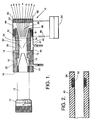
- FIG. 1 is a partial schematic representation of a preferred exemplary apparatus in accordance with the present invention.
- FIG. 2 is a partial sectional view of the embodiment shown in FIG. 1 showing the grounding ring and sleeve in assembled relation.
- the present invention relates to the use of any cleaning medium which, upon impingement on the chosen substrate, generates electrostatic charges on or near the substrate, including but not limited to the group of supercritical fluids which include nitrogen, argon, and neon.
- supercritical fluid is used herein to mean any fluid which has liquid-like densities when pressurized above its supercritical pressure and heated above its supercritical temperature.
- fluid as used herein means any substance or composition of substances comprising liquid, gas or solid particulates or any combination thereof.
- the present invention provides a means of controlling both desirable and undesirable electrostatic charges generated on or near a substrate upon impingement of a chosen cleaning medium on the chosen substrate and that the present invention can be used to impart or reduce said electrostatic charges.
- FIG. 1 A preferred exemplary apparatus is shown generally at 10 in FIG. 1.
- the apparatus 10 includes jet spray device 12, which includes valve assembly 14 and nozzle 30 which is attached to valve assembly 14.
- Valve assembly 14 includes housing 16, valve stem 18, and valve seat 20.
- Housing 16 includes inlet 22 for receiving liquid carbon dioxide (a preferred "compressed fluid” for precision cleaning applications) from an ultra-pure carbon dioxide source (not shown) and exit port 24 for transmitting the carbon dioxide snow (a preferred "expanded fluid” for precision cleaning applications) to nozzle 30.
- Valve stem 18 is axially movable in relation to valve seat 20 to form critical orifice 19 which controls the rate of flow of the cleaning snow to nozzle 30.
- Vernier 15 is provided on handle 13 for accurate and repeatable setting of the orifice 19.
- Nozzle 30 includes intake port 32 for receiving the cleaning snow from exit port 24 and nozzle throat 34 and outlet 36 for shaping the stream of cleaning snow and directing the stream of cleaning snow to the substrate surface (not shown).
- the length and internal diameter of nozzle 30 may vary widely, depending upon the surface to be cleaned, the degree of cleanliness desired and the cleaning medium to be applied to the chosen substrate.
- the length of nozzle 30 preferably will be between about 20 millimeters(mm) to 500 millimeters in order to provide optimum directional control of the carbon dioxide snow streams without losing cleaning efficiency.
- Preferred internal diameters for such applications are from between 1 to 13 mm.
- valve 14 is preferably a conventional needle, metering, regulating, solenoid or other valve commonly used to provide precise metering of gaseous materials.
- nozzle 30 may include a critical orifice and valve assembly 14 is provided only as a means of introducing the compressed fluid into jet spray device 12.
- Apparatus 10 as shown in FIG. 1 further includes a non-conductive sleeve 40, which is concentrically positioned over jet spray device 12.
- Sleeve 40 includes intake manifold 41 for receiving an expanded supplemental fluid, such as nitrogen, from a compressed supplemental fluid reservoir (not shown).
- Sleeve 40 has dimensions such that sleeve 40, when in assembled relation with jet spray device 12, defines supplemental fluid cavity 42 which is of sufficient size to produce a stream of expanded supplemental fluid and to enable the stream of expanded supplemental fluid to flow forwardly through supplemental fluid cavity 42 and surround the jet stream of cleaning snow as the cleaning snow flows from outlet 36 toward the chosen substrate.
- rearward end 46 of sleeve 40 is attached to housing 16, and forward end 48 of sleeve 40 extends sufficiently forward beyond outlet 36 to ensure that the stream of expanded supplemental fluid surrounds the cleaning snow during the cleaning process.
- inner wall 44 of sleeve 40 is complementary contoured to outer surface 38 of nozzle 30 thus enabling the stream of expanded supplemental fluid to complementary contour to the stream of cleaning snow.
- sleeve 40 is made from plastic or other material having non-conductive properties. Polytetrafluoroethylene is a preferred plastic material.
- sleeve 40 includes relief 50 located on inner wall 44 near the forward-most portion of sleeve 40.
- Relief 50 defines a concentric channel on inner wall 44 for receiving grounding ring 52 which is attachable to relief 50.
- Grounding ring 52 is complementary contoured to the shape of relief 50 such that grounding ring 52, when in assembled relation with relief 50, fills the concentric channel defined by relief 50.
- Grounding ring 52 is connectable to electric ground 54.
- Apparatus 10 as shown in FIG. 1 also includes electrodes 51 positioned in the stream of supplemental fluid forward of intake manifold 41 and rearward of grounding ring 52. Electrodes 51 are connectable in parallel to power supply 54. Alternatively, electrodes 51 are connected separately to power supply 54. This alternative arrangement allows electrodes 51 to be alternately charged by voltages from either an alternating current power supply or a pulsing direct current power supply. Electrodes 51 are configured to produce a non-linear voltage gradient whereby ionization of the expanded supplemental fluid is enhanced. Preferably, electrodes 51 are composed of a conductive material such as tungsten and are configured such that the length of electrodes 51 is substantially greater than the width of electrodes 51.
- power supply 54 provides about 5000 volts to electrodes 51.
- a 100 megaohm resistor 56 is connected in series between power supply 54 and electrodes 51 thereby reducing the current to apparatus 10 to microamperes.
- sleeve 40 will vary in accordance with the application and the size and shape of nozzle 30.
- the ionization of the stream of expanded supplemental fluid can be accomplished by impressing a source of electric potential across any first conductive surface, located in the stream of expanded supplemental fluid rearward of the substrate, and any second conductive surface, located in the stream of expanded supplemental fluid between the first conductive surface and the substrate.
- the source of electric potential need not produce 5000 volts but rather need only be sufficiently high to generate an electric field of sufficient intensity to ionize the stream of expanded supplemental fluid.
- ionization may be accomplished by introducing a radioactive stream of ionizing particles, such as alpha-emitters, into the stream of expanded fluid or into the stream of expanded supplemental fluid or by otherwise directing a radioactive stream of ionizing particles towards the substrate surface during the cleaning process.
- a radioactive stream of ionizing particles such as alpha-emitters
- any source of ionizable compressed fluid can be used as the source of the expanded supplemental fluid if condensation of moisture on the substrate is not a problem. It should be further understood that in cleaning applications wherein condensation of moisture on the substrate is a problem, any ultra-pure source of compressed supplemental fluid can be used as the source of the expanded supplemental fluid.
- the compressed supercritical fluid be utilized not only as the source of expanded supercritical fluid but also as the source of expanded supplemental fluid thereby obviating the need for separate reservoirs for the compressed supercritical fluid and the compressed supplemental fluid.
- control of electrostatic charges on or near the substrate surface is accomplished by impressing a source of electric potential across a first conductive surface, located directly in the stream of cleaning snow forward of outlet 36 and rearward of the substrate, and a second conductive surface, located directly in the stream of cleaning snow between the first conductive surface and the substrate.
- power supply 56 be a direct current pulsing power supply wherein the current across the first and second conductive surfaces alternates cyclically.
- the temperature and pressure of the carbon dioxide entering jet spray device 12 from inlet 22 is controlled in accordance with well known prior teachings regarding the formation of carbon dioxide snow.
- the carbon dioxide is preferably maintained at pressures on the order of 850 pounds per square inch (58.6 bar) prior to entering the snow forming jet spray device 12.
- the velocity and particle size of the cleaning snow may be varied depending upon the type of surface being cleaned and the amount of contaminants present. Preferably, the velocity will be adjusted to achieve maximum cleaning efficiency while causing minimal surface damage to the substrate. Stream velocities on the order of 0.5 meters per second to 10 meters per second are generally suitable for removing most common contaminants from thin film optical materials.
- the particle sizes of the carbon dioxide ice entrained in the snow stream also can be varied depending upon the surface to be cleaned and the contaminants to be removed. Snow size can be varied to clean off submicron particles. For most applications, particle sizes for the carbon dioxide snow will be on the order of 0.1 micron to 100 microns.
- the size of contaminant particles and compounds which can be removed utilizing carbon dioxide snow are generally on the order of submicrons to hundreds of microns in diameter.
- Molecular film contaminants which can be removed by the present invention are generally on the order of a few angstroms to several microns thick.
- Contaminants which can be cleaned by the system include particulates such as beryllium, cadmium, arsenic, selenium, chromium and uranium and their oxides or salts which are many times present in optical or precision mechanical systems.
- Other toxic contaminants, including organic oils, inorganic dusts, and the like, are amenable to cleaning utilizing the present invention.
- the preferred apparatus is not designed to provide cleaning of very large amounts of contaminants from surfaces. Instead, the apparatus is intended for use as a final cleaning step to provide the ultra-clean surfaces (i.e. "precision cleaning") which are required in high precision optical and electronic equipment and precision hardware.
- the apparatus and method of the present invention are well-suited for use in cleaning surfaces on parts which are designed for use at cryogenic temperatures.
- nitrogen, argon or neon may be utilized in place of carbon dioxide.
- the use of carbon dioxide is preferred because of its relatively low cost in comparison to the other gases, especially neon, and the low cost of the equipment required to produce carbon dioxide snow from liquid carbon dioxide.
Landscapes
- Engineering & Computer Science (AREA)
- Mechanical Engineering (AREA)
- Cleaning Or Drying Semiconductors (AREA)
- Cleaning In General (AREA)
- Application Of Or Painting With Fluid Materials (AREA)
- Spray Control Apparatus (AREA)
Applications Claiming Priority (2)
| Application Number | Priority Date | Filing Date | Title |
|---|---|---|---|
| US07/952,126 US5409418A (en) | 1992-09-28 | 1992-09-28 | Electrostatic discharge control during jet spray |
| US952126 | 1992-09-28 |
Publications (3)
| Publication Number | Publication Date |
|---|---|
| EP0590495A2 true EP0590495A2 (fr) | 1994-04-06 |
| EP0590495A3 EP0590495A3 (en) | 1994-06-01 |
| EP0590495B1 EP0590495B1 (fr) | 1997-05-14 |
Family
ID=25492613
Family Applications (1)
| Application Number | Title | Priority Date | Filing Date |
|---|---|---|---|
| EP93115274A Expired - Lifetime EP0590495B1 (fr) | 1992-09-28 | 1993-09-22 | ContrÔle de décharge électrostatique pendant l'enlèvement des contaminants de surfaces par jet pulvérisateur |
Country Status (5)
| Country | Link |
|---|---|
| US (1) | US5409418A (fr) |
| EP (1) | EP0590495B1 (fr) |
| JP (1) | JPH06190311A (fr) |
| CA (1) | CA2105743C (fr) |
| DE (1) | DE69310660T2 (fr) |
Cited By (5)
| Publication number | Priority date | Publication date | Assignee | Title |
|---|---|---|---|---|
| EP0728529A3 (fr) * | 1995-02-27 | 1996-11-13 | Hughes Aircraft Co | Dispositif modulaire de pulvérisation de CO2 |
| WO2000000326A1 (fr) * | 1998-06-29 | 2000-01-06 | L'air Liquide, Societe Anonyme Pour L'etude Et L'exploitation Des Procedes Georges Claude | Procede et dispositif pour nettoyer un masque de circuit imprime ou un circuit imprime |
| FR2997332A1 (fr) * | 2012-10-30 | 2014-05-02 | Air Liquide | Dispositif de projection de glace carbonique pour le nettoyage de cartes electroniques |
| WO2017059996A1 (fr) * | 2015-10-07 | 2017-04-13 | Bayerische Motoren Werke Aktiengesellschaft | Dispositif servant à nettoyer des surfaces de collage au moyen de dioxyde de carbone solide |
| US11364588B2 (en) | 2015-10-07 | 2022-06-21 | Bayerische Motoren Werke Aktiengesellschaft | Method for cleaning using solid carbon dioxide |
Families Citing this family (39)
| Publication number | Priority date | Publication date | Assignee | Title |
|---|---|---|---|---|
| US5868878A (en) * | 1993-08-27 | 1999-02-09 | Hughes Electronics Corporation | Heat treatment by plasma electron heating and solid/gas jet cooling |
| US5514024A (en) * | 1993-11-08 | 1996-05-07 | Ford Motor Company | Nozzle for enhanced mixing in CO2 cleaning system |
| US5931721A (en) * | 1994-11-07 | 1999-08-03 | Sumitomo Heavy Industries, Ltd. | Aerosol surface processing |
| US6103016A (en) * | 1994-12-05 | 2000-08-15 | Lucent Technologies Inc. | Mitigation of electrostatic discharges during carbon dioxide cleaning |
| US5651834A (en) * | 1995-08-30 | 1997-07-29 | Lucent Technologies Inc. | Method and apparatus for CO2 cleaning with mitigated ESD |
| US5846338A (en) * | 1996-01-11 | 1998-12-08 | Asyst Technologies, Inc. | Method for dry cleaning clean room containers |
| US5616067A (en) * | 1996-01-16 | 1997-04-01 | Ford Motor Company | CO2 nozzle and method for cleaning pressure-sensitive surfaces |
| US5922138A (en) * | 1996-08-12 | 1999-07-13 | Tokyo Electron Limited | Liquid treatment method and apparatus |
| US5837064A (en) * | 1996-10-04 | 1998-11-17 | Eco-Snow Systems, Inc. | Electrostatic discharge protection of static sensitive devices cleaned with carbon dioxide spray |
| US5836809A (en) * | 1996-10-07 | 1998-11-17 | Eco-Snow Systems, Inc. | Apparatus and method for cleaning large glass plates using linear arrays of carbon dioxide (CO2) jet spray nozzles |
| US6146466A (en) * | 1997-02-14 | 2000-11-14 | Eco-Snow Systems, Inc. | Use of electrostatic bias to clean non-electrostatically sensitive components with a carbon dioxide spray |
| US6053803A (en) * | 1997-09-16 | 2000-04-25 | S.S. White Technologies Inc. | Apparatus and method for generating a pressurized fluid stream having abrasive particles |
| US5928434A (en) * | 1998-07-13 | 1999-07-27 | Ford Motor Company | Method of mitigating electrostatic charge during cleaning of electronic circuit boards |
| US6319102B1 (en) * | 1999-07-09 | 2001-11-20 | International Business Machines Corporation | Capacitor coupled chuck for carbon dioxide snow cleaning system |
| RU2167756C2 (ru) * | 1999-08-27 | 2001-05-27 | Кострица Владимир Николаевич | Способ термоабразивной обработки поверхностей и устройство для его осуществления |
| US6419566B1 (en) * | 2000-02-11 | 2002-07-16 | International Business Machines Corporation | System for cleaning contamination from magnetic recording media rows |
| AU2001247406A1 (en) * | 2000-03-13 | 2001-10-15 | The Deflex Llc | Dense fluid spray cleaning process and apparatus |
| SE524570C2 (sv) * | 2000-12-18 | 2004-08-31 | Sinterkil Ab | Anordning för att bekämpa skadedjur, insekter eller ohyra medelst nedkylning |
| KR100389015B1 (ko) * | 2001-02-19 | 2003-06-25 | 한국전력공사 | Co₂ 스노우 제염장치 |
| US7451941B2 (en) * | 2001-03-13 | 2008-11-18 | Jackson David P | Dense fluid spray cleaning process and apparatus |
| US6656017B2 (en) | 2001-04-24 | 2003-12-02 | David P. Jackson | Method and apparatus for creating an open cell micro-environment for treating a substrate with an impingement spray |
| US7108584B2 (en) * | 2001-09-26 | 2006-09-19 | Fuji Photo Film Co., Ltd. | Method and apparatus for manufacturing liquid drop ejecting head |
| US20050217706A1 (en) * | 2002-04-05 | 2005-10-06 | Souvik Banerjee | Fluid assisted cryogenic cleaning |
| US6852173B2 (en) * | 2002-04-05 | 2005-02-08 | Boc, Inc. | Liquid-assisted cryogenic cleaning |
| JP3949504B2 (ja) * | 2002-04-25 | 2007-07-25 | 英夫 吉田 | 母材表面の活性化処理方法および活性化処理装置 |
| US20040045578A1 (en) * | 2002-05-03 | 2004-03-11 | Jackson David P. | Method and apparatus for selective treatment of a precision substrate surface |
| JP2004066112A (ja) * | 2002-08-07 | 2004-03-04 | Canon Inc | 乾式ブラスト洗浄における被洗浄物の除電方法および装置 |
| KR20040101948A (ko) * | 2004-05-31 | 2004-12-03 | (주)케이.씨.텍 | 표면세정용 승화성 고체입자 분사용 노즐 및 이를 이용한 세정방법 |
| MX2007007081A (es) * | 2004-12-13 | 2007-12-07 | Cool Clean Technologies Inc | Composiciones de fluido criogenico. |
| US20090126760A1 (en) * | 2005-01-12 | 2009-05-21 | Boc, Inc. | System for cleaning a surface using crogenic aerosol and fluid reactant |
| US7389941B2 (en) | 2005-10-13 | 2008-06-24 | Cool Clean Technologies, Inc. | Nozzle device and method for forming cryogenic composite fluid spray |
| US8048830B1 (en) | 2008-06-19 | 2011-11-01 | Cool Clean Technologies, Inc. | Method of forming and using carbonated machining fluid |
| US8454409B2 (en) * | 2009-09-10 | 2013-06-04 | Rave N.P., Inc. | CO2 nozzles |
| US10639691B1 (en) | 2012-01-05 | 2020-05-05 | David P. Jackson | Method for forming and applying an oxygenated machining fluid |
| US9387511B1 (en) | 2012-04-15 | 2016-07-12 | Cleanlogix Llc | Particle-plasma ablation process for polymeric ophthalmic substrate surface |
| CN205325427U (zh) * | 2016-02-02 | 2016-06-22 | 北京京东方显示技术有限公司 | 一种基板研磨装置 |
| WO2018187513A1 (fr) | 2017-04-04 | 2018-10-11 | Cleanlogix Llc | Applicateur par pulvérisation électrostatique passive d'un composite de co2 |
| DE102018118067A1 (de) | 2018-07-26 | 2020-01-30 | Ecoclean Gmbh | Reinigungsvorrichtung |
| CN109531435B (zh) * | 2019-01-27 | 2024-02-27 | 浙江工业大学 | 基于电荷尖端聚集效应的静电可控磨粒流加工系统 |
Family Cites Families (15)
| Publication number | Priority date | Publication date | Assignee | Title |
|---|---|---|---|---|
| US3600632A (en) * | 1968-12-03 | 1971-08-17 | Technology Uk | Static electricity dishcarge systems |
| US4132567A (en) * | 1977-10-13 | 1979-01-02 | Fsi Corporation | Apparatus for and method of cleaning and removing static charges from substrates |
| FR2419647A1 (fr) * | 1978-03-10 | 1979-10-05 | Onera (Off Nat Aerospatiale) | Dispositif pour produire un jet gazeux porteur de charges electriques |
| DE2938863A1 (de) * | 1979-09-26 | 1981-04-09 | Agfa-Gevaert Ag, 5090 Leverkusen | Einrichtung zum kontaktlosen entfernen von staub |
| FR2492212A1 (fr) * | 1980-10-14 | 1982-04-16 | Onera (Off Nat Aerospatiale) | Procede et dispositifs pour transferer des charges electriques de signes differents dans une zone d'espace et application aux eliminateurs d'electricite statique |
| JPS605529A (ja) * | 1983-06-23 | 1985-01-12 | Nec Corp | 洗浄装置 |
| US4535576A (en) * | 1984-03-28 | 1985-08-20 | Pennwalt Corporation | Anti-static process for abrasive jet machining |
| DE3603041A1 (de) * | 1985-04-11 | 1986-10-30 | Zöll, Dieter, Selzach | Flaechenreinigungsgeraet |
| US4677704A (en) * | 1986-04-22 | 1987-07-07 | Huggins Richard A | Cleaning system for static charged semiconductor wafer surface |
| JPS63126588A (ja) * | 1986-11-17 | 1988-05-30 | 増田 閃一 | 超微細粒子除去装置 |
| US4806171A (en) * | 1987-04-22 | 1989-02-21 | The Boc Group, Inc. | Apparatus and method for removing minute particles from a substrate |
| US4832753A (en) * | 1987-05-21 | 1989-05-23 | Tempress Measurement & Control Corporation | High-purity cleaning system, method, and apparatus |
| US4936922A (en) * | 1987-05-21 | 1990-06-26 | Roger L. Cherry | High-purity cleaning system, method, and apparatus |
| US4962891A (en) * | 1988-12-06 | 1990-10-16 | The Boc Group, Inc. | Apparatus for removing small particles from a substrate |
| JP2825301B2 (ja) * | 1990-02-14 | 1998-11-18 | 三菱電機株式会社 | 微細凍結粒子による洗浄装置 |
-
1992
- 1992-09-28 US US07/952,126 patent/US5409418A/en not_active Expired - Lifetime
-
1993
- 1993-09-08 CA CA002105743A patent/CA2105743C/fr not_active Expired - Lifetime
- 1993-09-22 DE DE69310660T patent/DE69310660T2/de not_active Expired - Lifetime
- 1993-09-22 EP EP93115274A patent/EP0590495B1/fr not_active Expired - Lifetime
- 1993-09-28 JP JP5241811A patent/JPH06190311A/ja active Pending
Cited By (7)
| Publication number | Priority date | Publication date | Assignee | Title |
|---|---|---|---|---|
| EP0728529A3 (fr) * | 1995-02-27 | 1996-11-13 | Hughes Aircraft Co | Dispositif modulaire de pulvérisation de CO2 |
| US5611491A (en) * | 1995-02-27 | 1997-03-18 | Hughes Aircraft Company | Modular CO2 jet spray device |
| WO2000000326A1 (fr) * | 1998-06-29 | 2000-01-06 | L'air Liquide, Societe Anonyme Pour L'etude Et L'exploitation Des Procedes Georges Claude | Procede et dispositif pour nettoyer un masque de circuit imprime ou un circuit imprime |
| FR2997332A1 (fr) * | 2012-10-30 | 2014-05-02 | Air Liquide | Dispositif de projection de glace carbonique pour le nettoyage de cartes electroniques |
| WO2017059996A1 (fr) * | 2015-10-07 | 2017-04-13 | Bayerische Motoren Werke Aktiengesellschaft | Dispositif servant à nettoyer des surfaces de collage au moyen de dioxyde de carbone solide |
| US11161219B2 (en) | 2015-10-07 | 2021-11-02 | Bayerische Motoren Werke Aktiengesellschaft | Device for cleaning adhesive surfaces using solid carbon dioxide |
| US11364588B2 (en) | 2015-10-07 | 2022-06-21 | Bayerische Motoren Werke Aktiengesellschaft | Method for cleaning using solid carbon dioxide |
Also Published As
| Publication number | Publication date |
|---|---|
| JPH06190311A (ja) | 1994-07-12 |
| EP0590495B1 (fr) | 1997-05-14 |
| EP0590495A3 (en) | 1994-06-01 |
| DE69310660D1 (de) | 1997-06-19 |
| US5409418A (en) | 1995-04-25 |
| DE69310660T2 (de) | 1997-11-27 |
| CA2105743A1 (fr) | 1994-03-29 |
| CA2105743C (fr) | 1998-11-03 |
Similar Documents
| Publication | Publication Date | Title |
|---|---|---|
| US5409418A (en) | Electrostatic discharge control during jet spray | |
| EP0622129B1 (fr) | Dispositif de nettoyage à deux jets | |
| US5837064A (en) | Electrostatic discharge protection of static sensitive devices cleaned with carbon dioxide spray | |
| JP2765787B2 (ja) | ジェットスプレイによる正確な洗浄のためのシステムおよび方法 | |
| US5853128A (en) | Solid/gas carbon dioxide spray cleaning system | |
| Sherman | Carbon dioxide snow cleaning | |
| US4806171A (en) | Apparatus and method for removing minute particles from a substrate | |
| KR102276667B1 (ko) | 광학 조립체, 특히 플라즈마 광원 또는 euv 리소그래피 시스템 | |
| US5853962A (en) | Photoresist and redeposition removal using carbon dioxide jet spray | |
| US5765578A (en) | Carbon dioxide jet spray polishing of metal surfaces | |
| CA2170866A1 (fr) | Systemes de nettoyage domestique utilisant un sac | |
| CA2019862A1 (fr) | Methode et appareil pour le nettoyage in situ d'appareils lasers a excimere | |
| CA2244657A1 (fr) | Procede et appareil permettant de couper, abraser et forer au moyen de particules sublimables et de liquides a l'etat de vapeur | |
| WO2001074538A1 (fr) | Améliorations apportées à un procédé, et à l'appareil correspondant, de nettoyage par pulvérisation d'un fluide dense | |
| WO2001084683A2 (fr) | Ioniseur de gaz en ligne et procede | |
| EP2956714B1 (fr) | Procédés et appareils destinés à être utilisés avec une lumière extrême-ultraviolette et ayant une protection contre la contamination | |
| KR20200123426A (ko) | 정화 장치 및 정화 방법 | |
| CN111344637A (zh) | 用于清洁的设备和方法 | |
| KR20030001306A (ko) | 세정방법 및 그 장치 | |
| US5482211A (en) | Supercritical fluid cleaning apparatus without pressure vessel | |
| EP0569708A1 (fr) | Appareil de nettoyage de surfaces solides par aerosol cryogénique | |
| US6319102B1 (en) | Capacitor coupled chuck for carbon dioxide snow cleaning system | |
| Peterson et al. | Contamination removal by CO2 jet spray | |
| US6146466A (en) | Use of electrostatic bias to clean non-electrostatically sensitive components with a carbon dioxide spray | |
| EP4335705A1 (fr) | Agencement de nettoyage de capteur de co2, procédé de commande de son fonctionnement, véhicule utilitaire et programme informatique |
Legal Events
| Date | Code | Title | Description |
|---|---|---|---|
| PUAI | Public reference made under article 153(3) epc to a published international application that has entered the european phase |
Free format text: ORIGINAL CODE: 0009012 |
|
| AK | Designated contracting states |
Kind code of ref document: A2 Designated state(s): DE FR GB NL |
|
| PUAL | Search report despatched |
Free format text: ORIGINAL CODE: 0009013 |
|
| RHK1 | Main classification (correction) |
Ipc: B24C 1/00 |
|
| AK | Designated contracting states |
Kind code of ref document: A3 Designated state(s): DE FR GB NL |
|
| 17P | Request for examination filed |
Effective date: 19941130 |
|
| 17Q | First examination report despatched |
Effective date: 19951228 |
|
| GRAG | Despatch of communication of intention to grant |
Free format text: ORIGINAL CODE: EPIDOS AGRA |
|
| GRAH | Despatch of communication of intention to grant a patent |
Free format text: ORIGINAL CODE: EPIDOS IGRA |
|
| GRAH | Despatch of communication of intention to grant a patent |
Free format text: ORIGINAL CODE: EPIDOS IGRA |
|
| GRAA | (expected) grant |
Free format text: ORIGINAL CODE: 0009210 |
|
| AK | Designated contracting states |
Kind code of ref document: B1 Designated state(s): DE FR GB NL |
|
| REF | Corresponds to: |
Ref document number: 69310660 Country of ref document: DE Date of ref document: 19970619 |
|
| ET | Fr: translation filed | ||
| PLBE | No opposition filed within time limit |
Free format text: ORIGINAL CODE: 0009261 |
|
| RAP2 | Party data changed (patent owner data changed or rights of a patent transferred) |
Owner name: HE HOLDINGS, INC. |
|
| 26N | No opposition filed | ||
| NLT2 | Nl: modifications (of names), taken from the european patent patent bulletin |
Owner name: HE HOLDINGS, INC. |
|
| REG | Reference to a national code |
Ref country code: GB Ref legal event code: IF02 |
|
| REG | Reference to a national code |
Ref country code: FR Ref legal event code: TP |
|
| NLS | Nl: assignments of ep-patents |
Owner name: ECO-SNOW SYSTEMS, INC. Effective date: 20051122 Owner name: BOC, INC. Effective date: 20051122 |
|
| NLT1 | Nl: modifications of names registered in virtue of documents presented to the patent office pursuant to art. 16 a, paragraph 1 |
Owner name: HE HOLDINGS, INC. |
|
| REG | Reference to a national code |
Ref country code: GB Ref legal event code: 732E |
|
| PGFP | Annual fee paid to national office [announced via postgrant information from national office to epo] |
Ref country code: NL Payment date: 20080903 Year of fee payment: 16 |
|
| REG | Reference to a national code |
Ref country code: NL Ref legal event code: V1 Effective date: 20100401 |
|
| PG25 | Lapsed in a contracting state [announced via postgrant information from national office to epo] |
Ref country code: NL Free format text: LAPSE BECAUSE OF NON-PAYMENT OF DUE FEES Effective date: 20100401 |
|
| REG | Reference to a national code |
Ref country code: GB Ref legal event code: 732E Free format text: REGISTERED BETWEEN 20101216 AND 20101222 |
|
| REG | Reference to a national code |
Ref country code: FR Ref legal event code: TP Ref country code: FR Ref legal event code: CD |
|
| REG | Reference to a national code |
Ref country code: DE Ref legal event code: R082 Ref document number: 69310660 Country of ref document: DE Representative=s name: WINTER, BRANDL, FUERNISS, HUEBNER, ROESS, KAIS, DE |
|
| REG | Reference to a national code |
Ref country code: DE Ref legal event code: R082 Ref document number: 69310660 Country of ref document: DE Representative=s name: WINTER, BRANDL, FUERNISS, HUEBNER, ROESS, KAIS, DE Effective date: 20111129 Ref country code: DE Ref legal event code: R081 Ref document number: 69310660 Country of ref document: DE Owner name: RAVE N.P., INC., US Free format text: FORMER OWNER: BOC, INC., NEW PROVIDENCE, US Effective date: 20111129 |
|
| PGFP | Annual fee paid to national office [announced via postgrant information from national office to epo] |
Ref country code: GB Payment date: 20120925 Year of fee payment: 20 |
|
| PGFP | Annual fee paid to national office [announced via postgrant information from national office to epo] |
Ref country code: FR Payment date: 20121001 Year of fee payment: 20 |
|
| PGFP | Annual fee paid to national office [announced via postgrant information from national office to epo] |
Ref country code: DE Payment date: 20120927 Year of fee payment: 20 |
|
| REG | Reference to a national code |
Ref country code: DE Ref legal event code: R071 Ref document number: 69310660 Country of ref document: DE |
|
| REG | Reference to a national code |
Ref country code: GB Ref legal event code: PE20 Expiry date: 20130921 |
|
| PG25 | Lapsed in a contracting state [announced via postgrant information from national office to epo] |
Ref country code: DE Free format text: LAPSE BECAUSE OF EXPIRATION OF PROTECTION Effective date: 20130924 |
|
| PG25 | Lapsed in a contracting state [announced via postgrant information from national office to epo] |
Ref country code: GB Free format text: LAPSE BECAUSE OF EXPIRATION OF PROTECTION Effective date: 20130921 |