EP0590622A1 - Entwicklungsgerät für Lichtempfindliches Material - Google Patents
Entwicklungsgerät für Lichtempfindliches Material Download PDFInfo
- Publication number
- EP0590622A1 EP0590622A1 EP93115668A EP93115668A EP0590622A1 EP 0590622 A1 EP0590622 A1 EP 0590622A1 EP 93115668 A EP93115668 A EP 93115668A EP 93115668 A EP93115668 A EP 93115668A EP 0590622 A1 EP0590622 A1 EP 0590622A1
- Authority
- EP
- European Patent Office
- Prior art keywords
- processing
- fluid
- photosensitive material
- entrance
- drain
- Prior art date
- Legal status (The legal status is an assumption and is not a legal conclusion. Google has not performed a legal analysis and makes no representation as to the accuracy of the status listed.)
- Withdrawn
Links
- 239000000463 material Substances 0.000 title claims abstract description 109
- 239000012530 fluid Substances 0.000 claims abstract description 206
- 239000000725 suspension Substances 0.000 claims description 15
- 230000008878 coupling Effects 0.000 description 2
- 238000010168 coupling process Methods 0.000 description 2
- 238000005859 coupling reaction Methods 0.000 description 2
- 238000000034 method Methods 0.000 description 2
- 230000000712 assembly Effects 0.000 description 1
- 238000000429 assembly Methods 0.000 description 1
- 238000010276 construction Methods 0.000 description 1
- 238000001816 cooling Methods 0.000 description 1
- 230000001419 dependent effect Effects 0.000 description 1
- 238000001035 drying Methods 0.000 description 1
- 238000010438 heat treatment Methods 0.000 description 1
- 230000014759 maintenance of location Effects 0.000 description 1
- 238000012986 modification Methods 0.000 description 1
- 230000004048 modification Effects 0.000 description 1
Images



Classifications
-
- G—PHYSICS
- G03—PHOTOGRAPHY; CINEMATOGRAPHY; ANALOGOUS TECHNIQUES USING WAVES OTHER THAN OPTICAL WAVES; ELECTROGRAPHY; HOLOGRAPHY
- G03D—APPARATUS FOR PROCESSING EXPOSED PHOTOGRAPHIC MATERIALS; ACCESSORIES THEREFOR
- G03D5/00—Liquid processing apparatus in which no immersion is effected; Washing apparatus in which no immersion is effected
- G03D5/04—Liquid processing apparatus in which no immersion is effected; Washing apparatus in which no immersion is effected using liquid sprays
Definitions
- the present invention relates to an apparatus for processing photosensitive materials, such as sheets of x-ray film.
- the present invention is directed to a processing apparatus of the type which includes an upper tank and a lower tank for holding processing fluid and a narrow processing chamber located between the tanks through which a sheet of photosensitive material is advanced for processing of latent images on the material.
- Processing fluid is delivered to opposite sides of the photosensitive material from each of the tanks for forming a fluid layer on each side of the photosensitive material.
- a return drain is provided on each side of the photosensitive material for removing and returning the processing fluid to the sump tank. Examples of such devices are illustrated in US-A-4,989,028; US-A-4,994,840; and US-A-5,059,997. Such devices are often referred to as fluid suspension processors.
- an apparatus for processing photosensitive materials having an upper and lower tank for holding processing fluid.
- the tanks are coupled together so that processing fluid can flow freely from the lower tank to the upper tank.
- a narrow processing chamber is provided between the upper and lower tanks through which the photosensitive material can be advanced for processing.
- the processing chamber has an entrance at one end and an exit at the other end which allow the photosensitive material to travel through the processing chamber.
- a first supply means is provided for supplying processing fluid from the upper tank to the processing chamber to create a first layer on one side of the photosensitive material.
- a first drain is provided for removing processing fluid from the first layer.
- a second supply means is provided for supplying processing fluid from the lower tank to the processing chamber to create a second fluid layer on the opposite side of the photosensitive material.
- a second drain is provided for removing material.
- Any number of photographic processing units can be included in the photographic process apparatus 10 depending upon the number of processing fluids required for processing a specific photosensitive material.
- the processor may, of course, include other elements typically found in processors.
- a dryer 20 may be provided for drying of the photosensitive material.
- a processing unit made in accordance with the present invention may be combined with other conventional processing units as desired.
- a plurality of sump tanks 23, 25, 27 for holding a processing fluid 22 are provided for units 14, 16, 18, respectively.
- the photosensitive material 12 is conveyed through the apparatus 10 by a plurality of nip rollers 28 associated with the photographic processing units 14, 16, 18.
- the rollers 28 can be driven by any conventional drive means (not shown).
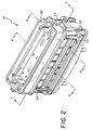
- processing unit 14 comprises an upper tank 30 and a lower tank 32 having fluid retention chambers 31, 33, respectively, for holding processing fluid 22.
- Four connecting tubes 34 connect the retention chambers 31, 33 of tanks 30 and 32 so as to allow processing fluid 22 to flow freely between the upper tank 30 and lower tank 32.
- the processing unit 14 further includes a processing section 36 located between the upper tank 30 and lower tank 32.
- the processing section 36 comprises an upper nozzle assembly 38 associated with the upper tank 30 and a lower nozzle assembly 40 associated with lower tank 32.
- the upper and lower nozzle assemblies 38, 40 define a narrow fluid processing chamber 42 through which the photosensitive material 12 travels during processing.
- the chamber 42 has an entrance 44 through which the photosensitive
- Processing fluid 22 is exhausted from chamber 42 by a pair of drains 66, 67 provided in inner nozzles 48, 56.
- the drains 66, 67 are located substantially midway between the entrance 44 and exit 46.
- the drains 66, 67 each comprise at least one opening provided in the substantially flat surfaces of inner nozzles 48, 56.
- drains 66, 67 each comprise a plurality of aligned opening 68 disposed at an angle a with respect to the direction of fluid flow (as indicated by arrow 69 in Figure 6) across the inner nozzles 48, 56.
- the drains 66, 67 may comprise any desired number of openings 68 having any desired configuration.
- Conduits or passageways 70, 72 are formed between the inner nozzles 48, 56 and tanks 30, 32 respectively for exhausting the fluid 22 from the chamber 42.
- the conduits 70, 72 terminate in outlets 76, 78 for emptying the fluid to the sump tank 23.
- the conduits 70, 72 are configured such that the outlets 76, 78 are positioned at substantially the same level so that the fluid back pressure that is experienced at the drains 66, 67 is substantially equal. In the particular embodiment illustrated this is achieved by providing a substantially straight conduit 70 having outlet 76 located at a first predetermined level or height and providing conduit 72 with a substantially straight horizontal section 77 and a vertical section 79 which locates outlet 78 at substantially the same level or height as outlet 76. It is, of course, understood that the particular configuration of conduits may take a variety of other shapes so long as the outlets 76, 78 remain at substantially the same level.
- a pair of weirs 91 are provided adjacent the outlets 76, 78 for receiving the processing fluid.
- Each of the weirs 91 includes a wall having an upper edge 97 which is adjacent the outlets 76,78 and a receiving chamber 84 into which the fluid 22 flows.
- the weirs 91 each have an opening 86 in the bottom for allowing fluid to return to the sump tank 23.
- the weirs 91 each have a substantially rectangular configuration and are sized such that the opening 86 is substantially always below the top of the fluid in sump tank 23. The size of opening 86 is such that the level of fluid 22 within weir 91 will be maintained slightly below the upper edge 97.
- a pump 51 is used to draw processing fluid from the sump tank 23 into the lower input 85 of the lower tank 32.
- the pump 51 causes the fluid 22 to go into the lower chamber 33, which in turn causes the processing fluid 22 to go into vertical tubes 34 so that processing fluid 22 will fill the upper tank 30 as best seen by reference to Figure 5.
- This will cause fluid 22 to fill both the upper and lower tanks 30, 32 such that substantially equal fluid pressure is applied to the outlets 53, 61 at the entrance 44 and exit 46 of the chamber 42.
- a pair of small air vent openings 80 are provided in conduits 72 so as to allow processing fluid 22 to drain from conduits 70,72 when the pump 51 is turned off.
- the openings 80 are small enough so as not to interfere with the substantially equal back pressure experienced by the drains 66, 67, but are of a sufficient size to allow fluid 22 to drain from the conduits to the sump tank.
- openings 80 each comprise a circular hole having a diameter of .09375 inches (.238 cms).
- a heat exchanger 98 is provided for cooling of the processing fluid.
- An optional heater 137 may also be provided for heating of the processing fluid when necessary. While the drawings illustrate the pump 51 located outside of the sump tank 23, it could equally be located within the sump tank 23, if desired. Additionally, appropriate connections may be provided for connecting of the sump tank to the pump and to the lower tank 32 by suitable means.
- the present invention is directed to an apparatus for processing photosensitive material which includes an upper and lower tank coupled together so that processing fluid can freely flow between the upper and lower tanks.
- the processor of the present invention provides a fluid processing layer through which the photosensitive material must pass.
- the present invention further provides means for providing substantially equal back pressure to both sides of the film, thereby minimizing or eliminating artifacts due to fluttering of the film within the processing chamber.
Landscapes
- Physics & Mathematics (AREA)
- General Physics & Mathematics (AREA)
- Photographic Processing Devices Using Wet Methods (AREA)
Applications Claiming Priority (2)
| Application Number | Priority Date | Filing Date | Title |
|---|---|---|---|
| US07/956,135 US5317359A (en) | 1992-10-02 | 1992-10-02 | Apparatus for processing photosensitive material |
| US956135 | 1992-10-02 |
Publications (1)
| Publication Number | Publication Date |
|---|---|
| EP0590622A1 true EP0590622A1 (de) | 1994-04-06 |
Family
ID=25497795
Family Applications (1)
| Application Number | Title | Priority Date | Filing Date |
|---|---|---|---|
| EP93115668A Withdrawn EP0590622A1 (de) | 1992-10-02 | 1993-09-29 | Entwicklungsgerät für Lichtempfindliches Material |
Country Status (4)
| Country | Link |
|---|---|
| US (1) | US5317359A (de) |
| EP (1) | EP0590622A1 (de) |
| JP (1) | JPH06202299A (de) |
| CA (1) | CA2105442A1 (de) |
Citations (1)
| Publication number | Priority date | Publication date | Assignee | Title |
|---|---|---|---|---|
| US4994840A (en) * | 1990-03-16 | 1991-02-19 | Eastman Kodak Company | Apparatus for processing photosensitive material |
Family Cites Families (5)
| Publication number | Priority date | Publication date | Assignee | Title |
|---|---|---|---|---|
| US4101919A (en) * | 1976-08-02 | 1978-07-18 | Quantor Corporation | Film processing apparatus |
| DE3535980C1 (de) * | 1985-10-09 | 1986-11-20 | Agfa-Gevaert Ag, 5090 Leverkusen | Vorrichtung zur Nassbehandlung fotografischer Schichttraeger |
| US4989028A (en) * | 1989-10-25 | 1991-01-29 | Eastman Kodak Company | Apparatus for processing light sensitive material |
| US5063951A (en) * | 1990-07-19 | 1991-11-12 | International Business Machines Corporation | Fluid treatment device |
| US5059997A (en) * | 1990-12-17 | 1991-10-22 | Eastman Kodak Company | Apparatus for processing photosensitive material |
-
1992
- 1992-10-02 US US07/956,135 patent/US5317359A/en not_active Expired - Fee Related
-
1993
- 1993-09-02 CA CA002105442A patent/CA2105442A1/en not_active Abandoned
- 1993-09-29 EP EP93115668A patent/EP0590622A1/de not_active Withdrawn
- 1993-10-04 JP JP5247800A patent/JPH06202299A/ja active Pending
Patent Citations (1)
| Publication number | Priority date | Publication date | Assignee | Title |
|---|---|---|---|---|
| US4994840A (en) * | 1990-03-16 | 1991-02-19 | Eastman Kodak Company | Apparatus for processing photosensitive material |
Also Published As
| Publication number | Publication date |
|---|---|
| US5317359A (en) | 1994-05-31 |
| CA2105442A1 (en) | 1994-04-03 |
| JPH06202299A (ja) | 1994-07-22 |
Similar Documents
| Publication | Publication Date | Title |
|---|---|---|
| US5357307A (en) | Apparatus for processing photosensitive material | |
| EP0446768B1 (de) | Gerät zur Entwicklung von lichtempfindlichem Material | |
| KR100237072B1 (ko) | 사진처리장치용 슬롯 밀집 구조 | |
| JP2981113B2 (ja) | 感光材処理装置 | |
| JPH06332141A (ja) | 感光材料処理装置 | |
| JP2726235B2 (ja) | 織物面のチャネルを有する感光材処理装置 | |
| US4312585A (en) | Method and apparatus for treating graphic arts process photosensitive materials | |
| EP0491181B1 (de) | Entwicklungsgerät für lichtempfindliches Material | |
| JP2928093B2 (ja) | モジュラー処理チャネルを有する感光材処理装置 | |
| EP0590622A1 (de) | Entwicklungsgerät für Lichtempfindliches Material | |
| US5302996A (en) | Apparatus for processing photosensitive material | |
| US5239327A (en) | Processor for light sensitive material | |
| JP2928090B2 (ja) | 感光材処理装置 | |
| JPH08171188A (ja) | 感光材料の処理装置 | |
| JP2928094B2 (ja) | スロットノズルを有する感光材処理装置 | |
| US5903795A (en) | Photographic processor | |
| US5335039A (en) | Apparatus for processing photosensitive material | |
| EP0590619A1 (de) | Gerät zur Behandlung eines Fotoempfindlichen Materials | |
| JPH10326002A (ja) | 写真処理装置 | |
| JP3755695B2 (ja) | 繊維製品の気流式処理装置 | |
| JP2931486B2 (ja) | 自動現像機の処理液ろ過機構 | |
| JP3626640B2 (ja) | 基板処理装置 | |
| CA2115735C (en) | Modular processing channel for an automatic tray processor | |
| US20040062546A1 (en) | Washing method and apparatus | |
| JPH0437752A (ja) | 感光材料処理装置の処理液温度調節装置 |
Legal Events
| Date | Code | Title | Description |
|---|---|---|---|
| PUAI | Public reference made under article 153(3) epc to a published international application that has entered the european phase |
Free format text: ORIGINAL CODE: 0009012 |
|
| AK | Designated contracting states |
Kind code of ref document: A1 Designated state(s): CH DE FR GB IT LI |
|
| 17P | Request for examination filed |
Effective date: 19940929 |
|
| 17Q | First examination report despatched |
Effective date: 19971212 |
|
| STAA | Information on the status of an ep patent application or granted ep patent |
Free format text: STATUS: THE APPLICATION HAS BEEN WITHDRAWN |
|
| 18W | Application withdrawn |
Withdrawal date: 19980205 |