EP0590664B1 - Appareil pour orienter des produits - Google Patents
Appareil pour orienter des produits Download PDFInfo
- Publication number
- EP0590664B1 EP0590664B1 EP93115810A EP93115810A EP0590664B1 EP 0590664 B1 EP0590664 B1 EP 0590664B1 EP 93115810 A EP93115810 A EP 93115810A EP 93115810 A EP93115810 A EP 93115810A EP 0590664 B1 EP0590664 B1 EP 0590664B1
- Authority
- EP
- European Patent Office
- Prior art keywords
- platform
- conveyor
- product
- articles
- support plane
- Prior art date
- Legal status (The legal status is an assumption and is not a legal conclusion. Google has not performed a legal analysis and makes no representation as to the accuracy of the status listed.)
- Expired - Lifetime
Links
- 239000000047 product Substances 0.000 description 30
- 239000007858 starting material Substances 0.000 description 8
- 239000007787 solid Substances 0.000 description 7
- 101150004219 MCR1 gene Proteins 0.000 description 4
- 101100136062 Mycobacterium tuberculosis (strain ATCC 25618 / H37Rv) PE10 gene Proteins 0.000 description 4
- 238000010276 construction Methods 0.000 description 4
- 108700012262 E coli mcr-2 Proteins 0.000 description 2
- 101000629937 Homo sapiens Translocon-associated protein subunit alpha Proteins 0.000 description 2
- 101000629913 Homo sapiens Translocon-associated protein subunit beta Proteins 0.000 description 2
- 101000629921 Homo sapiens Translocon-associated protein subunit delta Proteins 0.000 description 2
- 101000697347 Homo sapiens Translocon-associated protein subunit gamma Proteins 0.000 description 2
- 101100136063 Mycobacterium tuberculosis (strain ATCC 25618 / H37Rv) PE11 gene Proteins 0.000 description 2
- 102100026231 Translocon-associated protein subunit alpha Human genes 0.000 description 2
- 102100026229 Translocon-associated protein subunit beta Human genes 0.000 description 2
- 102100026226 Translocon-associated protein subunit delta Human genes 0.000 description 2
- 102100028160 Translocon-associated protein subunit gamma Human genes 0.000 description 2
- 235000015173 baked goods and baking mixes Nutrition 0.000 description 2
- 238000010586 diagram Methods 0.000 description 2
- 239000000463 material Substances 0.000 description 2
- 230000001012 protector Effects 0.000 description 2
- 235000008429 bread Nutrition 0.000 description 1
- 239000006227 byproduct Substances 0.000 description 1
- 230000000694 effects Effects 0.000 description 1
- 230000000977 initiatory effect Effects 0.000 description 1
- 238000007689 inspection Methods 0.000 description 1
- 230000003993 interaction Effects 0.000 description 1
- 230000013011 mating Effects 0.000 description 1
- 238000000926 separation method Methods 0.000 description 1
Images


Classifications
-
- B—PERFORMING OPERATIONS; TRANSPORTING
- B65—CONVEYING; PACKING; STORING; HANDLING THIN OR FILAMENTARY MATERIAL
- B65G—TRANSPORT OR STORAGE DEVICES, e.g. CONVEYORS FOR LOADING OR TIPPING, SHOP CONVEYOR SYSTEMS OR PNEUMATIC TUBE CONVEYORS
- B65G65/00—Loading or unloading
-
- B—PERFORMING OPERATIONS; TRANSPORTING
- B65—CONVEYING; PACKING; STORING; HANDLING THIN OR FILAMENTARY MATERIAL
- B65B—MACHINES, APPARATUS OR DEVICES FOR, OR METHODS OF, PACKAGING ARTICLES OR MATERIALS; UNPACKING
- B65B5/00—Packaging individual articles in containers or receptacles, e.g. bags, sacks, boxes, cartons, cans, jars
- B65B5/10—Filling containers or receptacles progressively or in stages by introducing successive articles, or layers of articles
- B65B5/106—Filling containers or receptacles progressively or in stages by introducing successive articles, or layers of articles by pushers
-
- B—PERFORMING OPERATIONS; TRANSPORTING
- B65—CONVEYING; PACKING; STORING; HANDLING THIN OR FILAMENTARY MATERIAL
- B65G—TRANSPORT OR STORAGE DEVICES, e.g. CONVEYORS FOR LOADING OR TIPPING, SHOP CONVEYOR SYSTEMS OR PNEUMATIC TUBE CONVEYORS
- B65G47/00—Article or material-handling devices associated with conveyors; Methods employing such devices
- B65G47/22—Devices influencing the relative position or the attitude of articles during transit by conveyors
- B65G47/24—Devices influencing the relative position or the attitude of articles during transit by conveyors orientating the articles
- B65G47/244—Devices influencing the relative position or the attitude of articles during transit by conveyors orientating the articles by turning them about an axis substantially perpendicular to the conveying plane
-
- B—PERFORMING OPERATIONS; TRANSPORTING
- B65—CONVEYING; PACKING; STORING; HANDLING THIN OR FILAMENTARY MATERIAL
- B65G—TRANSPORT OR STORAGE DEVICES, e.g. CONVEYORS FOR LOADING OR TIPPING, SHOP CONVEYOR SYSTEMS OR PNEUMATIC TUBE CONVEYORS
- B65G2203/00—Indexing code relating to control or detection of the articles or the load carriers during conveying
- B65G2203/04—Detection means
- B65G2203/042—Sensors
Definitions
- the present invention relates generally to improvements in apparatus orienting articles to a proper loading orientation and for loading articles into a container. More specifically, the invention relates to the loading of pliable packages of fragile items, such as bakery goods, into containers, such as trays or baskets.
- Prior product orienting and loading systems are known, one such system being disclosed in US-A-4,856,263 to Schneider et al. That system reorients the product by the use of a turntable disposed beneath the upper flight of a window conveyor.
- the apparatus must push the product twice during the reorienting operation.
- the window conveyor carries or pushes the product against a stop which holds it while the window conveyor runs out beneath it to allow the product to drop through the window onto the turntable.
- the conveyor section of the window conveyor engages the product and pushes it off the turntable.
- These pushing operations can damage delicate and fragile products, such as bakery products. Furthermore, because of these pushing operations, only certain patterns of product can be accommodated on the turntable without being disturbed by the pushing operations.
- EP-A-0 070 399 discloses an orienter including a liftable turntable with slots to receive conveyor rollers therethrough in the lowered position of the turntable, but the slots are large so that each slot can receive more than one roller.
- An important feature of the invention is the provision of apparatus for orienting product which is very gentle in handling soft and fragile products.
- another feature of the invention is the provision of apparatus of the type set forth, which does not require pushing of the product during the orienting operation.
- product orienting apparatus comprising: conveyor means including a plurality of spaced-apart disks mounted for rotation about parallel axes and being substantially tangent to a common support plane, turntable means including a platform disposed substantially parallel to the support plane and having a plurality of slots therethrough, rotating means for rotating the platform about an axis disposed substantially perpendicular to the support plane, and lift means for moving the platform in the direction of the axis between a lowered position below the support plane with the disks received through the slots and a raised position above the support plane to accommodate rotation of the platform, all as shown in the prior art, the inventive contribution being that each of the slots is cruciform in shape and is dimensioned so that the slots respectively receive the disks therethrough in only a limited number of predetermined rotational orientations of the platform.
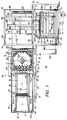
- FIGS. 1-3 there is illustrated an orienting and loading system, generally designated by the numeral 20, constructed in accordance with the present invention.
- the system 20 operates for assembling a group or pattern 21 of product articles 22, orienting the pattern and then loading it into a container 25, which may be a baking pan, basket or the like.
- the container 25 is illustrated as being a basket which includes a bottom wall 26 integral at its side edges with upstanding side walls 27 and at its end edges with upstanding end walls 28.
- Each of the side walls 27 and end walls 28 is preferably provided with an elongated recess 29 in the upper edge thereof centrally thereof.
- the container 25 may be formed of any suitable material, such as plastic, and each of the walls 27-29 may be perforated or of lattice-type construction to conserve material and weight, all in a known manner. While the principles of the present invention are operable in connection with the handling of various types of articles, for purposes of illustration, the construction and operation of the system 20 will be described in connection with the handling of soft and fragile articles, for example, articles of baked goods such as packages of sliced bread.
- the orienting and loading system 20 includes an infeed assembly 30 which receives the product articles from associated equipment, such as a bagger or the like (not shown).
- the infeed assembly 30 includes a frame 31 having a pair of elongated, upstanding and laterally spaced-apart side panels 32 supported on a plurality of upright legs 33.
- the side panels 32 may be interconnected by a plurality of spaced-apart cross members (not shown) in a known manner.
- Carried by the frame 31 adjacent to the lower end of one of the legs 33 is a horizontal platform 34 on which is mounted a drive motor 35 having a reducing gear box 36 provided with an output shaft 37 carrying a sprocket which engages a drive chain 38.
- the drive chain 38 is, in turn, coupled to a sprocket on a drive shaft 39 extending between the side panels 32.
- the infeed assembly 30 includes an infeed conveyor 40 comprising an endless conveyor belt 41 engaged with an idler roller 42 and a drive roller 43 which extend between the side panels 32 of the frame 31.
- the drive roller 43 is provided with a sprocket which is engaged with a drive chain 45 which is, in turn, engaged with a sprocket 46 on the drive shaft 39 to effect rotation of the infeed conveyor 40, so that the upper flight of the belt 41 moves in a direction of the arrow of FIG. 1.
- the infeed assembly 30 also includes a separating conveyor 50 which is disposed adjacent to the discharge end of the infeed conveyor 40 and includes an endless belt 51 engaged around an idler roller 52 and a drive roller 53 on the drive shaft 39, so that separating conveyor 50 is directly driven by the drive chain 38.
- the drive shaft 39 carries an additional sprocket 53, the teeth of which are counted by a counter PX10 mounted on the frame 31 for determining the length of travel of the separating conveyor 50.
- the sprockets are so sized that the separating conveyor 50 runs at a higher speed than the infeed conveyor 40, so that it will tend to separate articles received from the infeed conveyor 40.
- the infeed assembly 30 is also provided with a stop gate 55 disposed between the infeed and separating conveyors 40 and 50 and operable by a drive cylinder 56 for vertically reciprocating movement between a lowered position permitting free passage of articles from the infeed conveyor 40 and a raised position for stopping articles at the discharge end of the infeed conveyor 40.
- a stop gate 57 is also provided at the discharge end of the separating conveyor 50 and is similarly moveable between raised lowered and raised positions by a drive cylinder 58.
- guide rails 59 are respectively disposed along opposite sides of the infeed assembly 30 and have outwardly flared ends at the input end of the infeed conveyor 40, for guiding articles along the infeed assembly 30.
- the orienting and loading system 20 also includes an orienting assembly 60 which includes a powered disk conveyor 61 disposed at the discharge end of the separating conveyor 50 for receiving articles therefrom.
- the powered disk conveyor 61 includes a plurality of parallel shafts 62 extending between the side panels 32 and a pair of stub shafts 62a respectively extending laterally inwardly from the side panels 32 and having a length less than half the width of the conveyor 61.
- the inner ends of the stub shafts 62a are supported by suitable brackets coupled to adjacent ones of the shafts 62, so as to provide a central opening through the conveyor 61.
- each of the shafts 62 and 62a Fixedly secured to each of the shafts 62 and 62a is a plurality of laterally spaced-apart disks 63, arranged so that the disks on each shaft are disposed in staggered relationship with respect to the disks on adjacent shafts, and with all of the disks 63 being tangent to a common support plane, which is substantially coplanar with the support surface of the separating conveyor 50.
- the drive shaft 39 carries a double sprocket 64 which is engaged with a double-stranded drive chain 65 which also engages a sprocket coupled by a clutch to a shaft 66.
- the chain 65 also engages sprockets on each of the shafts 62 and the adjacent one of the stub shafts 62a for effecting rotation of the disks 63 carried thereby.
- a drive chain 68 is jumpered from a sprocket on one of the shafts 62 to a sprocket 69 on the stub shaft 62a on the far side of the disk conveyor 61 for rotating that shaft.
- the sprocket sizes are such that the powered disk conveyor 61 operates at a speed slightly less than that of the separating conveyor 50.
- the orienting assembly 60 also includes a turntable assembly 70 including a platform 71 which may be generally octagonal in shape and is provided with a plurality of cruciform slots 72 therethrough, dimensioned for respectively receiving the disks 63 therethrough.
- the platform 71 is disposed substantially parallel to the support plane of the powered disk conveyor 61 and is fixed centrally thereof to the upper end of an elongated vertical shaft 73, the lower end of which is coupled to a stepper motor 75.
- the shaft 73 extends through the opening in the center of the powered disk conveyor 61.
- the platform 71 and the stepper motor 75 are carried by a support frame 74.
- the support frame 74 includes a support plate 76 which is fixed to the stepper motor 75 and is vertically movable between fixed upper and lower plates 77 and 78. Air bags 79 are disposed between the movable support plate 76 and the upper and lower plates 77 and 78, respectively.
- the support plate 76 is normally disposed in a lowered position, wherein the platform 71 is disposed beneath the support plane of the powered disk conveyor 61, with the disks 63 being respectively received through the cruciform slots 72.
- the support plate 76 and the platform 71 are lifted to a raised position wherein the platform 71 is disposed above the support plane of the powered disk conveyor 61 clear of the disks 63.
- the stepper motor 75 is operable for rotating the platform 71 about the axis of the shaft 73 among a plurality of predetermined orientations, spaced apart by substantially 90°, so that when the platform 71 is again lowered, by inflation of the upper ones and deflation of the lower ones of the air bags 79, the disks 63 will still fit through the cruciform slots 72. It will be appreciated that when the platform 71 is in its lowered position, the powered disk conveyor carries articles from the separating conveyor 50 to a position overlying the platform 71, which then lifts the articles, rotates them to reorient them, and then lowers them back onto the powered disk conveyor 61, which carries them downstream to a transfer conveyor assembly 80.
- control of the orienting and loading system 20 is conducted from an operator interface 180 which may include a video screen 181 and an associated keyboard 182 and associated control switches. It is a significant aspect of the invention that the operation of the orienting and loading system 20 is controlled by a programmable logic controller including a processor operating under stored program control, interaction between the operator and the processor being conducted through the operator interface 180.
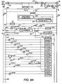
- the motors 35 and 115 which respectively drive the infeed assembly 30 and the loader assembly 110, are driven from a suitable AC supply, such as a 575-volt, three-phase, 60 Hz. supply, through a main disconnect switch 201, motor starter protect switches 202 and starter contactors 203.
- the primary of a control transformer 204 is connected across one phase of the three-phase supply and steps the voltage down to 115 VAC, the secondary of the transformer 204 being connected across 115 VAC lines 205 and 206.
- suitable fusing may be provided in the three-phase circuit and in the 115 VAC circuit.
- the programmable controller may be any of a number of different types of commercially available controllers.
- the disclosed system uses a controller sold by Texas Instruments Company under the designation 525-1104. Other controllers may require different AC supply arrangements.
- the controller is provided with input and output terminal modules, including a DC input module 226, an AC output module 227, an AC input module 228 and an AC output module 229. Associated with each terminal of these modules is a five-digit number designating the software address of the function associated with that terminal. Input terminal addresses begin with the letter "X" while output terminal addresses being with the letter "Y".
- a interlock relay XR Connected across the secondary of the control transformer 204 is the coil of a interlock relay XR. Connected in parallel with the XR relay coil is the series connection of a normally-closed push button power down switch 210, a normally-open push button power up switch 211 and a power on indicator lamp 212.
- the coil of a master control relay MCR is connected in parallel with the lamp 212 and its normally-open contacts MCR-2 are connected in parallel with the power up switch 211 for latching the circuit in an energized condition in response to momentary closure of the switch 211.
- a 24-VDC supply 213 Also connected in parallel with the lamp 212 is a 24-VDC supply 213 which provides a 24-VDC output voltage across a -DC line 214 and a +DCL line 215.
- the line 206 of the 115 VAC supply is connected through the normally-open contacts MCR-1 of the master control relay MCR to one normally-open pole of a three-pole push button emergency stop switch 216.
- the other fixed contact of that pole is connected through a lamp 217 to the common line 205 and to a line 218, discussed more fully below.
- the normally-open pole of the switch 216 is connected by a jumper 219 to a fixed contact of a normally-closed pole, the other contact of which is connected through a surge suppressor 220 to the common line 205.
- the third pole of the switch 216 is also normally-closed, and has one fixed contact thereof connected to the +DCL line 215 and the other fixed contact thereof connected to a line 221 to be discussed further below.
- the junction between the surge suppressor 220 and the emergency stop switch 216 is connected to an AC supply line 222.
- the control circuit 200 is powered up. If it is desired to shut the system down, the power down switch 210 is actuated to remove the AC voltage from the 24-VDC supply 213 and to reopen the relay contacts MCR-1 to remove the AC supply voltage from the remainder of the circuitry.
- the -DC supply line 214 is connected to the DC input terminal module 226 of the programmable controller. Respectively connected in parallel between the +DCL line 215 and corresponding DC input terminals of the controller are proximity switches PX10-PX13 and PX21-PX24. Also connected in parallel between the +DCL line 215 and corresponding DC input terminals of the controller are a guard switch 223, normally-open contacts MRA-1 and MRB-1, respectively, of an infeed motor starter MRA and loader motor starter MRB, and the contacts of a solid state relay SSR8. Also connected in parallel across the DC supply lines 214 and 215 are reflector-type photo eyes PE10, PE12, PE33 and PE34, the receiver terminals of which are respectively connected to corresponding DC input terminals of the controller. Also connected in parallel across the DC supply lines 214 and 215 are the emitter and receiver of a photo eye PE11, the receiver of which is connected to a corresponding DC input terminal of the controller.
- the AC supply line 222 is connected to the AC output terminal modules 227 and 229, while the AC supply common line 205 is connected to the AC input terminal module 228.
- the motor starter MRA for the infeed motor 35 and its contacts MRA-2 are connected in series between the AC line 205 and a corresponding AC output terminal of the controller.
- the motor starter MRB for the drive motor 115 and its contacts MRB-2 are connected in series between the line 205 and a corresponding AC output terminal of the controller.
- the contacts MRA-2 and MRB-2 are normally open contacts, but they are closed whenever the motor circuit protector switches 202 are closed and are, therefore, illustrated as closed in FIG. 8B.
- An alarm horn 224 and an alarm beacon 225 are connected between the line 218 from the emergency stop switch 216 and corresponding AC outputs of the controller.
- Respectively connected between corresponding AC outputs of the processor and the AC line 205 are coils of a need basket relay NBR and a basket lifted relay BLR, and the actuators of solid state relays SSR1, SSR2, SSR3, SSR5, SSR6 and SSR7.
- Also connected between the AC line 205 and corresponding AC output terminals of the controller are solenoid valves SV10-SV13 and SV20-SV23 and SV1-SV7.
- Connected between the AC line 222 and corresponding AC input terminals of the controller are photo eyes PE1-PE3 and proximity switches PX1-PX7.
- the stepper motor 75 is provided with a controller 230 which has its own internal software.
- This controller has connector sockets J4, J5, and J6 which receive mating connectors, the connector J5 being connected to the terminals of the stepper motor 75, the connector J6 being connected to the ground terminal and the AC lines 222 and 205 and the connector J4 being connected to the contacts of the solid state relays SSR1-SSR7 and to the actuator of the relay SSR8.
- the contacts of the relay SSR8 are connected across the +DCL line 215 and a DC input terminal of the controller, as can also be seen in FIG. 8A.
- the actuator of the solid state relay SSR4 is connected across the -DC line 214 and the line 233 (see FIG. 8A).
- the actuators of the other solid state relays are connected between the AC line 205 and corresponding AC output terminals of the processor, as was described above in connection with FIG. 8B.
- the signals from the controller AC output terminals connected to the solid state relays SSR5-SSR7 serve to select the particular program routine of the stepper controller 230 which corresponds to a preselected rotation of the turntable platform 71 for orienting the product articles 22.
- the stepper motor 75 will be operable only when the controller start relay SSR1 and the master stepper control relay SSR3 are actuated and the turntable platform 71 is in its raised position, as indicated by a signal to the relay SSR4. Whenever the turntable is in a rotating routine, a busy signal will appear at the relay SSR8 to prevent initiation of a further rotation program. A stop signal from the controller to the relay SSR2 will cause the stepper motor 75 to stop.
- the main disconnect switch 201 To operate the orienting and loading system 20, the main disconnect switch 201 must be closed. This provides power to the operator interface 180 via the power supply 209 and to the system processor via the power supply 208. When the power up switch 211 is closed, it is latched through the contacts MCR-2 of the master control relay MCR, the lamp 212 being illuminated to indicate that power is on. This energises the 24-VDC supply 213 for supplying DC power to the programmable controller, while closure of the relay contacts MCR-1 provides AC power to the programmable controller via the AC line 222 through the emergency stop switch 216.
- the system 20 is now ready for the operator to select product information via the operator interface 180.
- a product selection screen will appear on the video monitor 181, instructing the operator to select the product pattern to load via the keyboard 182.
- all the designated timing and counting registers are loaded from product storage registers into sequencer registers in the processor software.
- the operator has the choice of running a fixed number of articles or running continuously until a new product pattern is selected. After the choice has been made the start up screen is displayed and the system 20 is ready to run.
- the drive motors 35 and 115 for the infeed assembly 30 and the loader assembly 110 can be started by the operator from the keyboard 182. More specifically, the processor outputs AC signals at addresses Y0017 and Y0018 to the starters MRA and MRB, which close their contacts MRA-1 and MRB-1 to provide DC input signals to the processor at addresses X0013 and X0014.
- the infeed conveyor 40, the separating conveyor 50 and the powered disk conveyor 61 all begin operating and the loader assembly 110 is enabled.
- a product article 22 blocks the infeed photo eye PE10, it inputs a DC signal to the processor at address X0034.
- the infeed motor 35 will shut off and dwell if the photo eye PE10 is not blocked by product for a predetermined time period, and will restart when the photo eye PE10 is again blocked. Normally, the stop gate 55 is lowered.
- the stop gate 55 is lowered.
- the product articles 22 are counted by the count photo eye PE11, which inputs DC signals to the processor at address X0035 to increment a software counter.
- the articles traveling along the separating conveyor 50 are stopped by the stop gate 57, which is normally closed.
- the stop gate 57 which is normally closed.
- an AC signal will be output to the solenoid valve SV10 at address Y0023 to actuate the drive cylinder 56 and raise the stop gate 55 to hold back additional articles 22 until the previous group of articles 22 is advanced past the stop gate 57.
- the turntable platform 71 If the turntable platform 71 is in its lowered position, it will actuate the proximity sensor PX12 to input a DC signal to the processor at address X0003. If this occurs when the stop gate 55 is raised, the processor outputs an AC signal at address Y0026 to the solenoid valve SV11 to cause the drive cylinder 58 to lower the stop gate 57, allowing the assembled articles to pass from the separating conveyor 50 to the powered disk conveyor 61.
- the infeed conveyor position counter proximity sensor PX10 is mounted near the drive shaft 39 for counting the teeth of the sprocket 53, each sprocket tooth causing a DC signal to the input of the controller at address X0001 for incrementing a number of software counters.
- the processor will output an AC signal at address Y0024 to the solenoid valve SV10 to lower the stop gate 55 and allow additional articles to pass onto the infeed conveyor 40.
- the proximity sensor PX10 will increment counters for each of the several areas of the infeed assembly 30. When a counter corresponding to the powered disk conveyor 61 has reached a predetermined count after lowering of the stop gate 57, this will indicate that the articles on separating conveyor 50 should have passed completely onto the powered disk conveyor 61. This will cause the processor to output an AC signal at address Y0025 to the solenoid valve SV11 to raise the stop gate 57 back to its normal stop position. It will also output an AC signal at address Y0027 to the solenoid valve SV12 to cause the lower air bags 79 of the turntable 70 to be inflated to raise the platform 71, lifting the articles 22 a slight distance above the powered disk conveyor 61.
- the platform 71 When the platform 71 reaches its raised position, it actuates the proximity sensor PX11 to input a DC signal to the processor at address X0002. This will cause the processor to output AC signals to solid state relays SSR1-SSR3 and SSR5-SSR7 at addresses Y0053-Y0058 for actuating the stepper motor 75 through the stepper motor controller 230 (FIG. 9) to index the platform 71 through the required rotation to orient the articles 22 to the selected pattern.
- the stepper controller 230 is programmed so that the platform 71 can rotate bi-directionally in any 90° or 180° increment. During the stepper drive cycle, a turn in progress signal is sent to the processor at address X0033 to prevent the platform 71 from being lowered.
- the processor will output an AC signal at address Y0028 to the solenoid valve SV12 for deflating the lower air bags 79 and inflating the upper air bags 79 to lower the platform 71, returning the articles to the powered disk conveyor 61. Since the turntable assembly 70 can rotate in only 90° or 180° increments, the disks 63 will still fit through the cruciform slots 72 to permit return of the platform 71 to its lowered position. In its lowered position, the platform 71 will actuate the proximity switch PX13 to input a DC signal to the processor at address X0011.
- the transfer conveyor assembly 80 When the articles 22 have been returned to the powered disk conveyor 61, it will convey them from the orienting assembly 60 to the transfer conveyor assembly 80. As the articles block the photo eye PE12 at the exit of the orienting assembly 60, it will then input a DC signal to the processor at address X0036 causing it to output an AC signal at address Y0029 to the solenoid valve SV13 for engaging the clutch 83 on the drive shaft 66 to start the transfer conveyor belt 81. The transfer conveyor assembly 80 will run until the photo eye PE12 is cleared, if the pattern of articles is to be combined with another pattern before being pushed onto the loader assembly 110. If the pattern is not to be combined with another pattern, the transfer conveyor assembly 80 will run until a predetermined position count value has been reached in response to counter proximity sensor PX10. The stop plate 85 will prevent the articles from falling off the end of the transfer conveyor belt 81.
- the orienting and loading system 20 can be shut down by actuation of the emergency stop switch 216.
- the closure of the normally-open pole will energize the emergency lamp 217 and the emergency alarm horn 224 and beacon 225.
- the opening of the normally-closed poles will disconnect the DC and AC supply voltages from the controller. It will be appreciated that the system 20 could also be stopped by actuating the power down switch 210, which deenergizes the 24 VDC supply 213 and deenergizes the master control relay MCR for opening the AC supply at the contacts MCR-1.
Landscapes
- Engineering & Computer Science (AREA)
- Mechanical Engineering (AREA)
- Intermediate Stations On Conveyors (AREA)
- Control Of Conveyors (AREA)
Claims (3)
- Dispositif d'orientation de produits (60) comprenant : un moyen de transporteur (61) incluant une pluralité de disques espacés (63) montés en vue d'une rotation autour d'axes parallèles et étant pratiquement tangents à un plan d'un support commun, un moyen de plateau tournant (70) comprenant une plate-forme (71) disposée pratiquement parallèlement audit plan du support et comportant une pluralité de fentes (72) au travers de celui-ci, un moyen de mise en rotation (75) destiné à faire tourner ladite plate-forme autour d'un axe disposé pratiquement perpendiculairement audit plan du support, et un moyen d'élévateur (79) destiné à déplacer ladite plate-forme dans la direction dudit axe entre une position abaissée en-dessous dudit plan du support dans laquelle lesdits disques sont reçus au travers desdites fentes et une position relevée au-dessus dudit plan du support afin de prendre en compte la rotation de ladite plate-forme, caractérisé en ce que chacune desdites fentes est de forme cruciforme et est dimensionnée de façon à ce que lesdites fentes reçoivent respectivement lesdits disques au travers de celles-ci dans seulement un nombre limité d'orientations en rotation prédéterminées de ladite plate-forme.
- Dispositif selon la revendication 1, dans lequel ledit moyen de mise en rotation comprend un moteur pas-à-pas (75).
- Dispositif selon la revendication 1, et comprenant en outre un moyen de bâti (76) destiné à supporter ledit moyen de mise en rotation et ledit moyen de plateau tournant, ledit moyen d'élévateur comprenant un moyen destiné à relever et à abaisser ledit moyen de bâti.
Priority Applications (1)
| Application Number | Priority Date | Filing Date | Title |
|---|---|---|---|
| EP96118375A EP0765808A3 (fr) | 1992-09-30 | 1993-09-29 | Appareil pour charger des produits |
Applications Claiming Priority (2)
| Application Number | Priority Date | Filing Date | Title |
|---|---|---|---|
| US954953 | 1992-09-30 | ||
| US07/954,953 US5317859A (en) | 1992-09-30 | 1992-09-30 | Product orienter and loader |
Related Child Applications (1)
| Application Number | Title | Priority Date | Filing Date |
|---|---|---|---|
| EP96118375A Division EP0765808A3 (fr) | 1992-09-30 | 1993-09-29 | Appareil pour charger des produits |
Publications (3)
| Publication Number | Publication Date |
|---|---|
| EP0590664A2 EP0590664A2 (fr) | 1994-04-06 |
| EP0590664A3 EP0590664A3 (en) | 1994-09-21 |
| EP0590664B1 true EP0590664B1 (fr) | 1999-03-03 |
Family
ID=25496155
Family Applications (2)
| Application Number | Title | Priority Date | Filing Date |
|---|---|---|---|
| EP93115810A Expired - Lifetime EP0590664B1 (fr) | 1992-09-30 | 1993-09-29 | Appareil pour orienter des produits |
| EP96118375A Withdrawn EP0765808A3 (fr) | 1992-09-30 | 1993-09-29 | Appareil pour charger des produits |
Family Applications After (1)
| Application Number | Title | Priority Date | Filing Date |
|---|---|---|---|
| EP96118375A Withdrawn EP0765808A3 (fr) | 1992-09-30 | 1993-09-29 | Appareil pour charger des produits |
Country Status (4)
| Country | Link |
|---|---|
| US (1) | US5317859A (fr) |
| EP (2) | EP0590664B1 (fr) |
| CA (1) | CA2107270A1 (fr) |
| DE (1) | DE69323677D1 (fr) |
Cited By (1)
| Publication number | Priority date | Publication date | Assignee | Title |
|---|---|---|---|---|
| WO2014029855A1 (fr) * | 2012-08-22 | 2014-02-27 | Cryovac, Inc. | Transporteur et procédé de mise en rotation d'un produit |
Families Citing this family (29)
| Publication number | Priority date | Publication date | Assignee | Title |
|---|---|---|---|---|
| US5484050A (en) * | 1994-08-19 | 1996-01-16 | R. R. Donnelley & Sons Company | Catalog stacker and loader |
| GB9719522D0 (en) * | 1997-09-12 | 1997-11-19 | Newman Paul B D | Automated packaging |
| US6070389A (en) * | 1997-11-08 | 2000-06-06 | Irvin; John M. | Apparatus and method for wrapping articles |
| KR20010093262A (ko) | 1999-01-22 | 2001-10-27 | 피.암만,알,스타투네이토 | 손상된 보호 층 영역을 커버하는 방법, 상기 방법을수행하는 장치, 및 운반 시스템 |
| US6862869B2 (en) * | 1999-10-14 | 2005-03-08 | Stewart Systems, Inc. | Pattern former for wrapped bakery products |
| US7191578B2 (en) * | 1999-10-14 | 2007-03-20 | Stewart Systems, Inc. | Pattern former for wrapped bakery products and bakery tray loading system |
| US6401435B1 (en) | 1999-10-14 | 2002-06-11 | Sasib North America, Inc. | Pattern former and method of pattern forming for wrapped bakery products |
| US7305806B2 (en) * | 1999-10-14 | 2007-12-11 | Stewart Systems, Inc. | Pattern former for wrapped bakery products and method for loading and unloading bakery products |
| US6520314B1 (en) * | 2002-01-30 | 2003-02-18 | Samuel O. Seiling | Apparatus for arranging packaged bakery goods for shipment |
| DE502005005553D1 (de) * | 2004-12-07 | 2008-11-13 | Inventory Systems Gmbh | Stahlwarnvorrichtung |
| EP2036412B1 (fr) * | 2006-06-01 | 2012-11-14 | Exaflop LLC | Capture commandée d'air chaud |
| CA2653817C (fr) | 2006-06-01 | 2012-10-16 | Google Inc. | Environnements informatiques modulaires |
| DE102007052027B3 (de) * | 2007-10-31 | 2009-04-16 | Grenzebach Maschinenbau Gmbh | Verfahren und Vorrichtung zur kontaminationsfreien Behandlung stoßempfindlicher Glasplatten in Reinsträumen |
| WO2010094778A1 (fr) | 2009-02-19 | 2010-08-26 | Inventory Systems Gmbh | Dispositif d'alimentation pour déplacement automatique d'objets et procédé de détection d'un mouvement de l'unité d'alimentation de ce dispositif |
| CN102343988A (zh) * | 2010-08-03 | 2012-02-08 | 苏州澳昆智能机器人技术有限公司 | 立杯装置 |
| US9874414B1 (en) | 2013-12-06 | 2018-01-23 | Google Llc | Thermal control system |
| KR101736269B1 (ko) * | 2015-10-30 | 2017-05-16 | 주식회사 고영테크놀러지 | 물품 이송 장치 및 물품 검사 장치 |
| CN107176330B (zh) * | 2017-06-30 | 2019-04-12 | 嘉兴万源时装有限公司 | 一种用于包装盒封装的输送装置 |
| WO2019056468A1 (fr) * | 2017-09-23 | 2019-03-28 | 盐城旭华机械有限公司 | Mécanisme d'alimentation automatique pour planche en bois-plastique |
| DE102018204031A1 (de) * | 2018-03-16 | 2019-09-19 | Multivac Sepp Haggenmüller Se & Co. Kg | Förderbandsystem |
| EP3941855B1 (fr) * | 2019-03-20 | 2025-04-30 | Cryovac, LLC | Convoyeur et appareil d'emballage doté dudit convoyeur |
| EP3941856B1 (fr) * | 2019-03-20 | 2024-01-24 | Cryovac, LLC | Convoyeur et appareil d'emballage doté dudit convoyeur |
| CN110371638B (zh) * | 2019-08-07 | 2024-05-03 | 哈尔滨博实自动化股份有限公司 | 一种盘式整形机 |
| CN110371621B (zh) * | 2019-08-07 | 2024-06-21 | 哈尔滨博实自动化股份有限公司 | 拆垛生产线 |
| CN110562696B (zh) * | 2019-09-19 | 2024-11-19 | 上海恒浥智能科技股份有限公司 | 芯片自动输料机、芯片料盘、芯片自动检测线及其上料方法 |
| CN112079077A (zh) * | 2020-09-25 | 2020-12-15 | 海宁龙之岩自动化设备有限公司 | 一种物流自动分拣的易碎品贴签装置 |
| CN113173371B (zh) * | 2021-03-16 | 2022-05-20 | 亚细亚建筑材料股份有限公司 | 瓷砖加工用的送料定位装置 |
| CN114772171B (zh) * | 2022-04-02 | 2023-07-04 | 江苏徐工工程机械研究院有限公司 | 一种伸缩输送装置及刮板输送机 |
| CN118145345B (zh) * | 2024-04-12 | 2024-08-30 | 顺普汽车零部件(中国)有限公司 | 物料周转系统 |
Family Cites Families (23)
| Publication number | Priority date | Publication date | Assignee | Title |
|---|---|---|---|---|
| US2822932A (en) * | 1955-07-18 | 1958-02-11 | Greer J W Co | Material handling apparatus |
| US2875908A (en) * | 1955-10-20 | 1959-03-03 | Greer J W Co | Pallet loading apparatus |
| US2878948A (en) * | 1955-10-20 | 1959-03-24 | Greer J W Co | Pallet loading apparatus |
| US2897948A (en) * | 1957-08-20 | 1959-08-04 | Jr Albert E Cranston | Elevating turntable for conveyors |
| US3137286A (en) * | 1958-04-14 | 1964-06-16 | Mathews Conveyer Co | Pallet loading machine |
| US3045802A (en) * | 1959-02-04 | 1962-07-24 | Miller Engineering Corp | Method and apparatus for palletizing |
| US3471038A (en) * | 1962-12-26 | 1969-10-07 | Fmc Corp | Stack loading device |
| US3643822A (en) * | 1968-07-16 | 1972-02-22 | Hume Co G W | Can palletizer |
| US4000820A (en) * | 1972-05-01 | 1977-01-04 | Moorman Manufacturing Company | Method and apparatus for assembling layers of packages on a pallet |
| US3954190A (en) * | 1974-05-06 | 1976-05-04 | Wyard Industries, Inc. | Palletizer |
| US4041677A (en) * | 1975-10-06 | 1977-08-16 | Anderson Bros. Mfg. Co. | Packaging apparatus |
| US4030620A (en) * | 1975-12-15 | 1977-06-21 | Velten & Pulver, Inc. | Apparatus and method for loading containers |
| US4557656A (en) * | 1978-10-11 | 1985-12-10 | Ouellette Joseph F | Top feeding and ejecting materials handling apparatus |
| US4456116A (en) * | 1980-02-19 | 1984-06-26 | Jarman David J | Shear front feed system |
| DE3128917A1 (de) * | 1981-07-22 | 1983-03-10 | Weykam, Gottfried Johannes, Dr., 4700 Hamm | "dreheinrichtung fuer stueckgut, insbesondere fuer sackgut" |
| US4439084A (en) * | 1981-12-30 | 1984-03-27 | Harris Graphics Corporation | Palletizer for newspaper bundles |
| DE8220884U1 (de) * | 1982-07-22 | 1983-01-05 | Weykam, Gottfried J., Dr., 4700 Hamm | Vorrichtung zum stapeln von stueck- oder sackgut auf paletten |
| US4522292A (en) * | 1983-01-12 | 1985-06-11 | Velten & Pulver, Inc. | Pattern forming apparatus and product orienter therefor |
| US4856263A (en) * | 1987-06-15 | 1989-08-15 | Advanced Pulver Systems, Inc. | System for loading patterns of articles into containers |
| IT1233327B (it) * | 1989-07-26 | 1992-03-26 | Gap Tecnica Srl | Dispositivo automatico per rimozione di nidi o matassine di pasta alimentare, specie tagliatelle, lasagne e simili, dai telai di essicazione e relativo inserimento nei vassoi di confezionamento |
| US4974391A (en) * | 1989-08-22 | 1990-12-04 | Blossom Industries, Inc. | Automatic package loading system for bakery goods and the like |
| DE3929568A1 (de) * | 1989-09-06 | 1991-03-14 | Axmann Foerdertechnik | Vorrichtung zum entstapeln, befuellen und stapeln untereinander gleicher behaelter |
| US5180277A (en) * | 1990-07-06 | 1993-01-19 | Rapsco Incorporated | Can end handling system |
-
1992
- 1992-09-30 US US07/954,953 patent/US5317859A/en not_active Expired - Lifetime
-
1993
- 1993-09-29 EP EP93115810A patent/EP0590664B1/fr not_active Expired - Lifetime
- 1993-09-29 EP EP96118375A patent/EP0765808A3/fr not_active Withdrawn
- 1993-09-29 CA CA002107270A patent/CA2107270A1/fr not_active Abandoned
- 1993-09-29 DE DE69323677T patent/DE69323677D1/de not_active Expired - Lifetime
Cited By (1)
| Publication number | Priority date | Publication date | Assignee | Title |
|---|---|---|---|---|
| WO2014029855A1 (fr) * | 2012-08-22 | 2014-02-27 | Cryovac, Inc. | Transporteur et procédé de mise en rotation d'un produit |
Also Published As
| Publication number | Publication date |
|---|---|
| US5317859A (en) | 1994-06-07 |
| DE69323677D1 (de) | 1999-04-08 |
| EP0590664A2 (fr) | 1994-04-06 |
| EP0590664A3 (en) | 1994-09-21 |
| EP0765808A3 (fr) | 1997-07-23 |
| CA2107270A1 (fr) | 1994-03-31 |
| EP0765808A2 (fr) | 1997-04-02 |
Similar Documents
| Publication | Publication Date | Title |
|---|---|---|
| EP0590664B1 (fr) | Appareil pour orienter des produits | |
| EP0295872B1 (fr) | Système de chargement de groupes d'articles dans des conteneurs | |
| US3193078A (en) | Article divider for conveyors | |
| CA1216313A (fr) | Dispositif d'empilage de produits comestibles mous, generalement de forme plane | |
| US5253762A (en) | Stacking, counting and sorting device for flexible, planar food products | |
| US4710089A (en) | Article unstacking system | |
| JP2007525386A (ja) | 包装装置 | |
| US5765337A (en) | Apparatus and method for stacking and boxing stackable articles | |
| US4599025A (en) | Stacker assembly | |
| EP0380142B1 (fr) | Procédé et appareil pour le traitement d'une pile | |
| US5518361A (en) | Method and apparatus for the high-speed handling of compact disc storage containers with minimal product marking or damage | |
| US4955784A (en) | Apparatus for unstacking cross-nested articles | |
| US3715857A (en) | Bagel bagging machine | |
| US5335485A (en) | Flexible bag dispensing apparatus for use in supermarkets and the like | |
| US3339564A (en) | Machine for cleaning and assorting table silver and control mechanism therefor | |
| US4154043A (en) | Container loading system | |
| CN1324288C (zh) | 自动冷冻器构件 | |
| JPS61295929A (ja) | 自動処理物品の一時溜め装置 | |
| US3620387A (en) | Hook-type pallet unstacker with doubles eliminator | |
| US4199918A (en) | Cup loader machine | |
| US3303916A (en) | Automatic loading and conveyor apparatus | |
| JPH06227641A (ja) | 冷凍食品の整列搬送装置 | |
| SU1330007A1 (ru) | Устройство дл укладки изделий в тару | |
| JPH0744565Y2 (ja) | 角型容器整列取出装置 | |
| CA2130627A1 (fr) | Systeme de desempilage de plateaux et de transport par convoyeur |
Legal Events
| Date | Code | Title | Description |
|---|---|---|---|
| PUAI | Public reference made under article 153(3) epc to a published international application that has entered the european phase |
Free format text: ORIGINAL CODE: 0009012 |
|
| AK | Designated contracting states |
Kind code of ref document: A2 Designated state(s): DE DK FR GB NL |
|
| PUAL | Search report despatched |
Free format text: ORIGINAL CODE: 0009013 |
|
| AK | Designated contracting states |
Kind code of ref document: A3 Designated state(s): DE DK FR GB NL |
|
| 17P | Request for examination filed |
Effective date: 19941130 |
|
| 17Q | First examination report despatched |
Effective date: 19960510 |
|
| GRAG | Despatch of communication of intention to grant |
Free format text: ORIGINAL CODE: EPIDOS AGRA |
|
| GRAG | Despatch of communication of intention to grant |
Free format text: ORIGINAL CODE: EPIDOS AGRA |
|
| GRAH | Despatch of communication of intention to grant a patent |
Free format text: ORIGINAL CODE: EPIDOS IGRA |
|
| GRAH | Despatch of communication of intention to grant a patent |
Free format text: ORIGINAL CODE: EPIDOS IGRA |
|
| GRAA | (expected) grant |
Free format text: ORIGINAL CODE: 0009210 |
|
| AK | Designated contracting states |
Kind code of ref document: B1 Designated state(s): DE DK FR GB NL |
|
| PG25 | Lapsed in a contracting state [announced via postgrant information from national office to epo] |
Ref country code: NL Free format text: LAPSE BECAUSE OF FAILURE TO SUBMIT A TRANSLATION OF THE DESCRIPTION OR TO PAY THE FEE WITHIN THE PRESCRIBED TIME-LIMIT Effective date: 19990303 Ref country code: FR Free format text: LAPSE BECAUSE OF FAILURE TO SUBMIT A TRANSLATION OF THE DESCRIPTION OR TO PAY THE FEE WITHIN THE PRESCRIBED TIME-LIMIT Effective date: 19990303 |
|
| XX | Miscellaneous (additional remarks) |
Free format text: TEILANMELDUNG 96118375.3 EINGEREICHT AM 15/11/96. |
|
| REF | Corresponds to: |
Ref document number: 69323677 Country of ref document: DE Date of ref document: 19990408 |
|
| PG25 | Lapsed in a contracting state [announced via postgrant information from national office to epo] |
Ref country code: DK Free format text: LAPSE BECAUSE OF FAILURE TO SUBMIT A TRANSLATION OF THE DESCRIPTION OR TO PAY THE FEE WITHIN THE PRESCRIBED TIME-LIMIT Effective date: 19990603 |
|
| PG25 | Lapsed in a contracting state [announced via postgrant information from national office to epo] |
Ref country code: DE Free format text: LAPSE BECAUSE OF FAILURE TO SUBMIT A TRANSLATION OF THE DESCRIPTION OR TO PAY THE FEE WITHIN THE PRESCRIBED TIME-LIMIT Effective date: 19990605 |
|
| EN | Fr: translation not filed | ||
| NLV1 | Nl: lapsed or annulled due to failure to fulfill the requirements of art. 29p and 29m of the patents act | ||
| PGFP | Annual fee paid to national office [announced via postgrant information from national office to epo] |
Ref country code: DK Payment date: 19990906 Year of fee payment: 7 |
|
| PLBE | No opposition filed within time limit |
Free format text: ORIGINAL CODE: 0009261 |
|
| STAA | Information on the status of an ep patent application or granted ep patent |
Free format text: STATUS: NO OPPOSITION FILED WITHIN TIME LIMIT |
|
| 26N | No opposition filed | ||
| REG | Reference to a national code |
Ref country code: GB Ref legal event code: IF02 |
|
| PGFP | Annual fee paid to national office [announced via postgrant information from national office to epo] |
Ref country code: GB Payment date: 20020927 Year of fee payment: 10 |
|
| PG25 | Lapsed in a contracting state [announced via postgrant information from national office to epo] |
Ref country code: GB Free format text: LAPSE BECAUSE OF NON-PAYMENT OF DUE FEES Effective date: 20030929 |
|
| GBPC | Gb: european patent ceased through non-payment of renewal fee |
Effective date: 20030929 |