EP0590704A2 - Méthode et dispositif pour commander une conduite d'air de dérivation - Google Patents
Méthode et dispositif pour commander une conduite d'air de dérivation Download PDFInfo
- Publication number
- EP0590704A2 EP0590704A2 EP93202474A EP93202474A EP0590704A2 EP 0590704 A2 EP0590704 A2 EP 0590704A2 EP 93202474 A EP93202474 A EP 93202474A EP 93202474 A EP93202474 A EP 93202474A EP 0590704 A2 EP0590704 A2 EP 0590704A2
- Authority
- EP
- European Patent Office
- Prior art keywords
- pintle
- engine
- speed
- movement
- controlling
- Prior art date
- Legal status (The legal status is an assumption and is not a legal conclusion. Google has not performed a legal analysis and makes no representation as to the accuracy of the status listed.)
- Granted
Links
Images
Classifications
-
- F—MECHANICAL ENGINEERING; LIGHTING; HEATING; WEAPONS; BLASTING
- F02—COMBUSTION ENGINES; HOT-GAS OR COMBUSTION-PRODUCT ENGINE PLANTS
- F02D—CONTROLLING COMBUSTION ENGINES
- F02D31/00—Use of speed-sensing governors to control combustion engines, not otherwise provided for
- F02D31/001—Electric control of rotation speed
- F02D31/002—Electric control of rotation speed controlling air supply
- F02D31/003—Electric control of rotation speed controlling air supply for idle speed control
- F02D31/005—Electric control of rotation speed controlling air supply for idle speed control by controlling a throttle by-pass
-
- F—MECHANICAL ENGINEERING; LIGHTING; HEATING; WEAPONS; BLASTING
- F02—COMBUSTION ENGINES; HOT-GAS OR COMBUSTION-PRODUCT ENGINE PLANTS
- F02M—SUPPLYING COMBUSTION ENGINES IN GENERAL WITH COMBUSTIBLE MIXTURES OR CONSTITUENTS THEREOF
- F02M3/00—Idling devices for carburettors
- F02M3/06—Increasing idling speed
- F02M3/07—Increasing idling speed by positioning the throttle flap stop, or by changing the fuel flow cross-sectional area, by electrical, electromechanical or electropneumatic means, according to engine speed
-
- F—MECHANICAL ENGINEERING; LIGHTING; HEATING; WEAPONS; BLASTING
- F02—COMBUSTION ENGINES; HOT-GAS OR COMBUSTION-PRODUCT ENGINE PLANTS
- F02D—CONTROLLING COMBUSTION ENGINES
- F02D11/00—Arrangements for, or adaptations to, non-automatic engine control initiation means, e.g. operator initiated
- F02D11/06—Arrangements for, or adaptations to, non-automatic engine control initiation means, e.g. operator initiated characterised by non-mechanical control linkages, e.g. fluid control linkages or by control linkages with power drive or assistance
- F02D11/10—Arrangements for, or adaptations to, non-automatic engine control initiation means, e.g. operator initiated characterised by non-mechanical control linkages, e.g. fluid control linkages or by control linkages with power drive or assistance of the electric type
- F02D2011/101—Arrangements for, or adaptations to, non-automatic engine control initiation means, e.g. operator initiated characterised by non-mechanical control linkages, e.g. fluid control linkages or by control linkages with power drive or assistance of the electric type characterised by the means for actuating the throttles
- F02D2011/103—Arrangements for, or adaptations to, non-automatic engine control initiation means, e.g. operator initiated characterised by non-mechanical control linkages, e.g. fluid control linkages or by control linkages with power drive or assistance of the electric type characterised by the means for actuating the throttles at least one throttle being alternatively mechanically linked to the pedal or moved by an electric actuator
-
- F—MECHANICAL ENGINEERING; LIGHTING; HEATING; WEAPONS; BLASTING
- F02—COMBUSTION ENGINES; HOT-GAS OR COMBUSTION-PRODUCT ENGINE PLANTS
- F02D—CONTROLLING COMBUSTION ENGINES
- F02D9/00—Controlling engines by throttling air or fuel-and-air induction conduits or exhaust conduits
- F02D9/08—Throttle valves specially adapted therefor; Arrangements of such valves in conduits
- F02D9/10—Throttle valves specially adapted therefor; Arrangements of such valves in conduits having pivotally-mounted flaps
- F02D9/1035—Details of the valve housing
- F02D9/1055—Details of the valve housing having a fluid by-pass
Definitions
- the present invention relates to a method of and apparatus for controlling the movement of a pintle an internal combustion engine, particularly on returning to the idling mode after a perturbation, such as a change in throttle position.
- the idling speed of an engine is normally controlled by means of a pintle which is adapted to modify the cross-sectional area of an air channel which bypasses the throttle blade so as to modify the air flow through the bypass passage.
- the pintle is moved by a stepper motor under the control of an engine idling speed controller, which may be incorporated within an engine management system.
- the pintle When the engine idling speed controller is active and the throttle blade is in a closed position, the pintle is moved to a position which allows sufficient air flow to cause the engine to operate at a speed which substantially matches a desired engine speed.
- the desired engine speed is determined on the basis of predeterined engine operating conditions, such as engine coolant temperature, active engine loads, such as heating, lights and the air conditioning clutch, and variations in battery voltage.
- the stepper motor moves the pintle in a direction to increase the cross-sectional area of the bypass channel at a rate determined as a function of throttle movement.
- the stepper motor moves the pintle back towards the position it held before the throttle blade was opened.
- a problem encoutered in moving the pintle back to its engine idling position is that this can cause the engine to operate inconsistently for a short period.
- the present invention seeks to provide an improved method of and apparatus for controlling the movement of a pintle of an engine and in particular the movement of the pintle back to an engine idling position in a manner which can substantially prevent any instability in engine operation as a result of the movement of the pintle.
- the method comprises the step of setting the predetermined position as the sum of the position of the pintle at the time the throttle was last moved from an idling position to a more open position plus a predetermined offset determined as a function of vehicle speed; and enabling closed loop control of the engine idling speed after the pintle has reached the predetermined position. Setting the predetermined position in this manner ensures that the position the pintle moves to during a transition back to the idling mode is not inappropriate for the current vehicle speed.
- closed loop control of the engine idling speed is enabled when the actual engine speed becomes less than the desired engine idling speed. This ensures that the engine speed has substantially stabilised before returning to closed loop control.
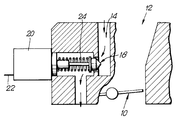
- a throttle valve 10 of conventional blade form is located within a choke 12 of an engine manifold and controls the flow of air from the engine manifold to the engine cylinders.
- a bypass channel 14 provides a passage in the choke 12 which bypasses the throttle 10 so as to enable air to be inducted into the cylinders when the throttle is closed, thereby enabling the engine to idle.
- Located within the bypass channel 14 is a valve seat 16 cooperable with a valve or pintle 18 which is movable to vary the cross-sectional area of the passage between the pintle 18 and the valve seat 16, thereby to vary the air flow rate through the bypass passage 14.
- the pintle 18 is of conventional form and includes a coil spring 24 for biasing the pintle towards the valve seat 16 and a shaft connected to a control valve 20, which comprises a stepper motor coupled to the shaft for moving the pintle away from the valve seat 16 against the force of the coil spring 24.
- An input 22 of the control valve 20 is coupled to an engine management system which includes an engine idling speed controller for controlling the control valve 20.
- control valve 20 adjusts the position of the pintle 18 to provide a flow of air appropriate to cause the engine to idle at a desired engine speed determined on the basis of the detected engine operating conditions.
- detected engine operating conditions include, for example, engine coolant temperature, active engine loads, such as air conditioning clutch and lights, and variations in battery voltage.
- the pintle 18 When the throttle blade 10 is moved to an open position on depression of the accelerator pedal, the pintle 18 is moved away from the valve seat 16 at a rate determined as a function of the movement of the throttle blade 10 so as to increase the air flow through the bypass channel 14.
- the pintle 18 On return of the throttle blade 10 to its closed position, the pintle 18 is moved back towards the valve seat 16 so as to adjust the air flow through the bypass passage 14 by an amount sufficient to bring the engine speed to the desired engine idling speed, determined on the basis of the above-mentioned engine operating conditions.
- the rate at which the pintle 18 is moved back towards the valve seat 16 is determined as a function of the difference between the actual engine speed and the desired engine speed.
- variable TIME in the above equation represents the rate of movement of the pintle, that is the time taken for the pintle to move by a predetermined amount.
- the pintle 18 is moved on the basis of the above equation until it reaches a return position relative to the valve seat 16 corresponding to the initial position of the pintle 18 at the time the throttle blade 10 was first opened plus a calibratable offset determined as a function of the vehicle speed.
- This calibratable offset is chosen as the point at which normal closed loop control of the engine idling speed can begin, and from which further movement of the pintle under normal closed loop control is not likely to cause any engine operating instabilities.
- the commencement of normal closed loop control of the engine idling speed by means of the pintle is delayed unless certain conditions have been satisfied.
- the condition to be satisfied is that the actual engine speed must drop below the desired engine speed, which in this example is around 800 RPM. While the engine speed is above the desired engine idling speed, closed loop control of the engine idling speed must meet the above-mentioned conditions. On the other hand, when the engine speed is less than the desired engine idling speed, closed loop control of the engine speed is enabled immediately.
Landscapes
- Engineering & Computer Science (AREA)
- Chemical & Material Sciences (AREA)
- Combustion & Propulsion (AREA)
- Mechanical Engineering (AREA)
- General Engineering & Computer Science (AREA)
- Electrical Control Of Air Or Fuel Supplied To Internal-Combustion Engine (AREA)
Applications Claiming Priority (2)
| Application Number | Priority Date | Filing Date | Title |
|---|---|---|---|
| GB9220582 | 1992-09-30 | ||
| GB9220582A GB2271196B (en) | 1992-09-30 | 1992-09-30 | Method and apparatus for controlling an air bypass passage |
Publications (3)
| Publication Number | Publication Date |
|---|---|
| EP0590704A2 true EP0590704A2 (fr) | 1994-04-06 |
| EP0590704A3 EP0590704A3 (fr) | 1994-11-17 |
| EP0590704B1 EP0590704B1 (fr) | 1998-02-11 |
Family
ID=10722727
Family Applications (1)
| Application Number | Title | Priority Date | Filing Date |
|---|---|---|---|
| EP19930202474 Expired - Lifetime EP0590704B1 (fr) | 1992-09-30 | 1993-08-23 | Méthode et dispositif pour commander une conduite d'air de dérivation |
Country Status (3)
| Country | Link |
|---|---|
| EP (1) | EP0590704B1 (fr) |
| DE (1) | DE69316953T2 (fr) |
| GB (1) | GB2271196B (fr) |
Cited By (1)
| Publication number | Priority date | Publication date | Assignee | Title |
|---|---|---|---|---|
| WO2007029104A2 (fr) | 2005-09-08 | 2007-03-15 | Toyota Jidosha Kabushiki Kaisha | Structure d'orifices d'admission pour moteur a combustion interne |
Families Citing this family (1)
| Publication number | Priority date | Publication date | Assignee | Title |
|---|---|---|---|---|
| RU2180706C2 (ru) * | 1998-07-15 | 2002-03-20 | Драгомиров Сергей Григорьевич | Система центрального впрыска топлива |
Family Cites Families (8)
| Publication number | Priority date | Publication date | Assignee | Title |
|---|---|---|---|---|
| JPS5825541A (ja) * | 1981-08-07 | 1983-02-15 | Nippon Denso Co Ltd | 内燃機関アイドル回転速度制御方法 |
| US4453514A (en) * | 1983-01-25 | 1984-06-12 | Motorola, Inc. | Engine speed adaptive air bypass valve (dashpot) control |
| JPS59168238A (ja) * | 1983-03-11 | 1984-09-21 | Honda Motor Co Ltd | 内燃エンジンのアイドル回転数フイ−ドバツク制御方法 |
| JPS6081442A (ja) * | 1983-10-08 | 1985-05-09 | Toyota Motor Corp | 内燃機関のアイドリング回転速度制御方法 |
| JPS61104133A (ja) * | 1984-10-26 | 1986-05-22 | Fuji Heavy Ind Ltd | 吸入空気流量制御装置 |
| JPS61223246A (ja) * | 1985-03-27 | 1986-10-03 | Fujitsu Ten Ltd | アイドル回転数制御装置 |
| JPS62111140A (ja) * | 1985-11-07 | 1987-05-22 | Mitsubishi Motors Corp | アイドル回転速度制御用ステツピングモ−タの初期化方法 |
| MX172111B (es) * | 1989-02-17 | 1993-12-03 | Orbital Eng Pty | Sistema de suministro de aire para un motor de combustion interna |
-
1992
- 1992-09-30 GB GB9220582A patent/GB2271196B/en not_active Expired - Lifetime
-
1993
- 1993-08-23 EP EP19930202474 patent/EP0590704B1/fr not_active Expired - Lifetime
- 1993-08-23 DE DE1993616953 patent/DE69316953T2/de not_active Expired - Lifetime
Cited By (3)
| Publication number | Priority date | Publication date | Assignee | Title |
|---|---|---|---|---|
| WO2007029104A2 (fr) | 2005-09-08 | 2007-03-15 | Toyota Jidosha Kabushiki Kaisha | Structure d'orifices d'admission pour moteur a combustion interne |
| WO2007029104A3 (fr) * | 2005-09-08 | 2007-05-03 | Toyota Motor Co Ltd | Structure d'orifices d'admission pour moteur a combustion interne |
| US7900595B2 (en) | 2005-09-08 | 2011-03-08 | Toyota Jidosha Kabushiki Kaisha | Intake port structure for internal combustion engine |
Also Published As
| Publication number | Publication date |
|---|---|
| GB2271196B (en) | 1995-08-16 |
| DE69316953T2 (de) | 1998-05-28 |
| GB9220582D0 (en) | 1992-11-11 |
| DE69316953D1 (de) | 1998-03-19 |
| EP0590704B1 (fr) | 1998-02-11 |
| GB2271196A (en) | 1994-04-06 |
| EP0590704A3 (fr) | 1994-11-17 |
Similar Documents
| Publication | Publication Date | Title |
|---|---|---|
| US4402289A (en) | Idle speed control method and system for an internal combustion engine | |
| KR880002075B1 (ko) | 스파아크 점화 내연기관용 전자(電子)조절식 연료 분사장치 | |
| US4441471A (en) | Apparatus for regulating the idling rpm of internal combustion engines | |
| US4365599A (en) | Open and closed loop engine idling speed control method and system for an automotive internal combustion engine | |
| US4203395A (en) | Closed-loop idle speed control system for fuel-injected engines using pulse width modulation | |
| US4344398A (en) | Idle speed control method and system for an internal combustion engine of an automotive vehicle | |
| JPH0445661B2 (fr) | ||
| EP1242736B1 (fr) | Commande de vitesse de ralenti de moteur | |
| GB2049037A (en) | System and method for controlling exhaust gas recirculation | |
| KR900700743A (ko) | 공회전 및 감속중의 내연기관의 공기비를 조절하는 방법 및 그 장치 | |
| JPS6316578B2 (fr) | ||
| US4976238A (en) | Apparatus for controlling the number of idle rotations of an internal combustion engine | |
| EP0590704B1 (fr) | Méthode et dispositif pour commander une conduite d'air de dérivation | |
| US5186080A (en) | Engine coastdown control system | |
| CA2030586C (fr) | Dispositif de regulation de l'air d'admission pour moteur a combustion interne | |
| JPS585452A (ja) | 電子制御エンジンのアイドル回転数制御方法 | |
| JP2555211B2 (ja) | 内燃機関の制御方法 | |
| JP2843182B2 (ja) | エンジンのアイドル回転数制御方法 | |
| JPH03134242A (ja) | エンジンのアイドル回転数制御装置 | |
| JP2672087B2 (ja) | デイーゼル機関の燃料噴射制御装置 | |
| JPH04342851A (ja) | エンジンのアイドル回転数制御方法 | |
| JPH02267360A (ja) | ディーゼルエンジンの排気還流制御装置 | |
| JPH0672137A (ja) | 車両用空調制御装置 | |
| JPH0252109B2 (fr) | ||
| JPH03182663A (ja) | 内燃機関のアイドル回転数制御装置 |
Legal Events
| Date | Code | Title | Description |
|---|---|---|---|
| PUAI | Public reference made under article 153(3) epc to a published international application that has entered the european phase |
Free format text: ORIGINAL CODE: 0009012 |
|
| AK | Designated contracting states |
Kind code of ref document: A2 Designated state(s): BE DE FR PT SE |
|
| PUAL | Search report despatched |
Free format text: ORIGINAL CODE: 0009013 |
|
| AK | Designated contracting states |
Kind code of ref document: A3 Designated state(s): BE DE FR PT SE |
|
| 17P | Request for examination filed |
Effective date: 19950517 |
|
| 17Q | First examination report despatched |
Effective date: 19961107 |
|
| GRAG | Despatch of communication of intention to grant |
Free format text: ORIGINAL CODE: EPIDOS AGRA |
|
| GRAG | Despatch of communication of intention to grant |
Free format text: ORIGINAL CODE: EPIDOS AGRA |
|
| GRAH | Despatch of communication of intention to grant a patent |
Free format text: ORIGINAL CODE: EPIDOS IGRA |
|
| GRAH | Despatch of communication of intention to grant a patent |
Free format text: ORIGINAL CODE: EPIDOS IGRA |
|
| GRAA | (expected) grant |
Free format text: ORIGINAL CODE: 0009210 |
|
| AK | Designated contracting states |
Kind code of ref document: B1 Designated state(s): BE DE FR PT SE |
|
| REF | Corresponds to: |
Ref document number: 69316953 Country of ref document: DE Date of ref document: 19980319 |
|
| ET | Fr: translation filed | ||
| PG25 | Lapsed in a contracting state [announced via postgrant information from national office to epo] |
Ref country code: PT Free format text: LAPSE BECAUSE OF FAILURE TO SUBMIT A TRANSLATION OF THE DESCRIPTION OR TO PAY THE FEE WITHIN THE PRESCRIBED TIME-LIMIT Effective date: 19980511 |
|
| PLBE | No opposition filed within time limit |
Free format text: ORIGINAL CODE: 0009261 |
|
| 26N | No opposition filed | ||
| REG | Reference to a national code |
Ref country code: FR Ref legal event code: TP |
|
| PGFP | Annual fee paid to national office [announced via postgrant information from national office to epo] |
Ref country code: SE Payment date: 20120829 Year of fee payment: 20 |
|
| PGFP | Annual fee paid to national office [announced via postgrant information from national office to epo] |
Ref country code: FR Payment date: 20120830 Year of fee payment: 20 Ref country code: DE Payment date: 20120829 Year of fee payment: 20 Ref country code: BE Payment date: 20120827 Year of fee payment: 20 |
|
| REG | Reference to a national code |
Ref country code: DE Ref legal event code: R071 Ref document number: 69316953 Country of ref document: DE |
|
| REG | Reference to a national code |
Ref country code: DE Ref legal event code: R071 Ref document number: 69316953 Country of ref document: DE |
|
| BE20 | Be: patent expired |
Owner name: *DELCO ELECTRONICS CORP. Effective date: 20130823 |
|
| REG | Reference to a national code |
Ref country code: SE Ref legal event code: EUG |
|
| PG25 | Lapsed in a contracting state [announced via postgrant information from national office to epo] |
Ref country code: DE Free format text: LAPSE BECAUSE OF EXPIRATION OF PROTECTION Effective date: 20130824 |