EP0590826B1 - Dispositif pour identifier un objet - Google Patents
Dispositif pour identifier un objet Download PDFInfo
- Publication number
- EP0590826B1 EP0590826B1 EP93307235A EP93307235A EP0590826B1 EP 0590826 B1 EP0590826 B1 EP 0590826B1 EP 93307235 A EP93307235 A EP 93307235A EP 93307235 A EP93307235 A EP 93307235A EP 0590826 B1 EP0590826 B1 EP 0590826B1
- Authority
- EP
- European Patent Office
- Prior art keywords
- light
- segments
- light receiving
- identifying
- layer
- Prior art date
- Legal status (The legal status is an assumption and is not a legal conclusion. Google has not performed a legal analysis and makes no representation as to the accuracy of the status listed.)
- Expired - Lifetime
Links
Images


Classifications
-
- G—PHYSICS
- G06—COMPUTING OR CALCULATING; COUNTING
- G06K—GRAPHICAL DATA READING; PRESENTATION OF DATA; RECORD CARRIERS; HANDLING RECORD CARRIERS
- G06K7/00—Methods or arrangements for sensing record carriers, e.g. for reading patterns
- G06K7/10—Methods or arrangements for sensing record carriers, e.g. for reading patterns by electromagnetic radiation, e.g. optical sensing; by corpuscular radiation
- G06K7/10544—Methods or arrangements for sensing record carriers, e.g. for reading patterns by electromagnetic radiation, e.g. optical sensing; by corpuscular radiation by scanning of the records by radiation in the optical part of the electromagnetic spectrum
- G06K7/10821—Methods or arrangements for sensing record carriers, e.g. for reading patterns by electromagnetic radiation, e.g. optical sensing; by corpuscular radiation by scanning of the records by radiation in the optical part of the electromagnetic spectrum further details of bar or optical code scanning devices
- G06K7/10831—Arrangement of optical elements, e.g. lenses, mirrors, prisms
-
- G—PHYSICS
- G03—PHOTOGRAPHY; CINEMATOGRAPHY; ANALOGOUS TECHNIQUES USING WAVES OTHER THAN OPTICAL WAVES; ELECTROGRAPHY; HOLOGRAPHY
- G03H—HOLOGRAPHIC PROCESSES OR APPARATUS
- G03H1/00—Holographic processes or apparatus using light, infrared or ultraviolet waves for obtaining holograms or for obtaining an image from them; Details peculiar thereto
- G03H1/02—Details of features involved during the holographic process; Replication of holograms without interference recording
- G03H1/0252—Laminate comprising a hologram layer
-
- G—PHYSICS
- G03—PHOTOGRAPHY; CINEMATOGRAPHY; ANALOGOUS TECHNIQUES USING WAVES OTHER THAN OPTICAL WAVES; ELECTROGRAPHY; HOLOGRAPHY
- G03H—HOLOGRAPHIC PROCESSES OR APPARATUS
- G03H1/00—Holographic processes or apparatus using light, infrared or ultraviolet waves for obtaining holograms or for obtaining an image from them; Details peculiar thereto
- G03H1/02—Details of features involved during the holographic process; Replication of holograms without interference recording
- G03H1/0272—Substrate bearing the hologram
-
- G—PHYSICS
- G06—COMPUTING OR CALCULATING; COUNTING
- G06K—GRAPHICAL DATA READING; PRESENTATION OF DATA; RECORD CARRIERS; HANDLING RECORD CARRIERS
- G06K19/00—Record carriers for use with machines and with at least a part designed to carry digital markings
- G06K19/06—Record carriers for use with machines and with at least a part designed to carry digital markings characterised by the kind of the digital marking, e.g. shape, nature, code
- G06K19/06009—Record carriers for use with machines and with at least a part designed to carry digital markings characterised by the kind of the digital marking, e.g. shape, nature, code with optically detectable marking
-
- G—PHYSICS
- G06—COMPUTING OR CALCULATING; COUNTING
- G06K—GRAPHICAL DATA READING; PRESENTATION OF DATA; RECORD CARRIERS; HANDLING RECORD CARRIERS
- G06K19/00—Record carriers for use with machines and with at least a part designed to carry digital markings
- G06K19/06—Record carriers for use with machines and with at least a part designed to carry digital markings characterised by the kind of the digital marking, e.g. shape, nature, code
- G06K19/08—Record carriers for use with machines and with at least a part designed to carry digital markings characterised by the kind of the digital marking, e.g. shape, nature, code using markings of different kinds or more than one marking of the same kind in the same record carrier, e.g. one marking being sensed by optical and the other by magnetic means
- G06K19/10—Record carriers for use with machines and with at least a part designed to carry digital markings characterised by the kind of the digital marking, e.g. shape, nature, code using markings of different kinds or more than one marking of the same kind in the same record carrier, e.g. one marking being sensed by optical and the other by magnetic means at least one kind of marking being used for authentication, e.g. of credit or identity cards
- G06K19/16—Record carriers for use with machines and with at least a part designed to carry digital markings characterised by the kind of the digital marking, e.g. shape, nature, code using markings of different kinds or more than one marking of the same kind in the same record carrier, e.g. one marking being sensed by optical and the other by magnetic means at least one kind of marking being used for authentication, e.g. of credit or identity cards the marking being a hologram or diffraction grating
-
- G—PHYSICS
- G03—PHOTOGRAPHY; CINEMATOGRAPHY; ANALOGOUS TECHNIQUES USING WAVES OTHER THAN OPTICAL WAVES; ELECTROGRAPHY; HOLOGRAPHY
- G03H—HOLOGRAPHIC PROCESSES OR APPARATUS
- G03H1/00—Holographic processes or apparatus using light, infrared or ultraviolet waves for obtaining holograms or for obtaining an image from them; Details peculiar thereto
- G03H1/0005—Adaptation of holography to specific applications
- G03H1/0011—Adaptation of holography to specific applications for security or authentication
-
- G—PHYSICS
- G03—PHOTOGRAPHY; CINEMATOGRAPHY; ANALOGOUS TECHNIQUES USING WAVES OTHER THAN OPTICAL WAVES; ELECTROGRAPHY; HOLOGRAPHY
- G03H—HOLOGRAPHIC PROCESSES OR APPARATUS
- G03H1/00—Holographic processes or apparatus using light, infrared or ultraviolet waves for obtaining holograms or for obtaining an image from them; Details peculiar thereto
- G03H1/02—Details of features involved during the holographic process; Replication of holograms without interference recording
- G03H1/024—Hologram nature or properties
- G03H1/0244—Surface relief holograms
-
- G—PHYSICS
- G03—PHOTOGRAPHY; CINEMATOGRAPHY; ANALOGOUS TECHNIQUES USING WAVES OTHER THAN OPTICAL WAVES; ELECTROGRAPHY; HOLOGRAPHY
- G03H—HOLOGRAPHIC PROCESSES OR APPARATUS
- G03H2222/00—Light sources or light beam properties
- G03H2222/31—Polarised light
-
- G—PHYSICS
- G03—PHOTOGRAPHY; CINEMATOGRAPHY; ANALOGOUS TECHNIQUES USING WAVES OTHER THAN OPTICAL WAVES; ELECTROGRAPHY; HOLOGRAPHY
- G03H—HOLOGRAPHIC PROCESSES OR APPARATUS
- G03H2240/00—Hologram nature or properties
- G03H2240/50—Parameters or numerical values associated with holography, e.g. peel strength
- G03H2240/55—Thickness
-
- G—PHYSICS
- G03—PHOTOGRAPHY; CINEMATOGRAPHY; ANALOGOUS TECHNIQUES USING WAVES OTHER THAN OPTICAL WAVES; ELECTROGRAPHY; HOLOGRAPHY
- G03H—HOLOGRAPHIC PROCESSES OR APPARATUS
- G03H2250/00—Laminate comprising a hologram layer
- G03H2250/36—Conform enhancement layer
-
- G—PHYSICS
- G03—PHOTOGRAPHY; CINEMATOGRAPHY; ANALOGOUS TECHNIQUES USING WAVES OTHER THAN OPTICAL WAVES; ELECTROGRAPHY; HOLOGRAPHY
- G03H—HOLOGRAPHIC PROCESSES OR APPARATUS
- G03H2250/00—Laminate comprising a hologram layer
- G03H2250/41—Polarisation active layer
-
- G—PHYSICS
- G06—COMPUTING OR CALCULATING; COUNTING
- G06K—GRAPHICAL DATA READING; PRESENTATION OF DATA; RECORD CARRIERS; HANDLING RECORD CARRIERS
- G06K19/00—Record carriers for use with machines and with at least a part designed to carry digital markings
- G06K19/06—Record carriers for use with machines and with at least a part designed to carry digital markings characterised by the kind of the digital marking, e.g. shape, nature, code
- G06K2019/06215—Aspects not covered by other subgroups
- G06K2019/0629—Holographic, diffractive or retroreflective recording
Definitions
- the present invention relates to a system for identifying an object suitable for determining the authenticity of the object.
- EP-A-0412316 reflecting the nearest prior art and filed by the same applicant, discloses a system for identifying an object by affixing an identification sticker which includes a hologram that contains a unique diffractive property, on the object to be identified, and radiating light upon this hologram so as to be diffracted by the hologram, and then receiving the diffracted light with an optical identification means.
- the forgery of the hologram is made highly difficult, making a reliable identification possible.
- the inventors of the present application have conceived of the idea (for the purpose of more positively discouraging forgery) that it is possible to use, in combination with the reflective directivity (or diffraction property), a light source for emitting linearly polarized light, a polarization plane rotating means provided in the identification element for rotating the polarization plane by 90 degrees, by shifting the phase of the polarized light by 180 degrees, and light receiving means which is sensitive only to the portion of the light emitted from the identification element whose polarization plane has been rotated by 90 degrees; thus the authenticity of the object may be identified according to the state of polarization.
- any attempt to forge the identification element can be more effectively discouraged.
- the intensity of the received light would not change significantly even when the amount of phase shift substantially deviated from 180 degrees, the intensity of the received light alone would not be sufficient for accurately detecting the phase shift of 180 degrees or the authenticity of the identification element.
- a polarization plane rotating layer in the form of a sticker or the like, on the identification element for the purpose of achieving the phase shift of approximately 180 degrees for deceptive purposes.
- a primary object of the present invention is to provide a system for identifying an object which provides an improved power of identification.
- a second object of the present invention is to provide a system for identifying an object which is difficult to analyze or shows very little clue as to its working principle so that any attempt to forge it may be effectively discouraged.
- a third object of the present invention is to provide a system for identifying an object which is difficult to forge through analysis of its structure.
- a fourth object of the present invention is to provide a system for identifying an object which is difficult to forge but economical to fabricate.
- the authenticity of the object is verified only when the light emitting means emits a light beam having a prescribed wavelength and polarization plane, the light receiving means in cooperation with the determination means detects the presence of the light receiving element having a distinctive diffractive property or a reflective directivity, and the light receiving element, with the aid of the first and second filters, again in cooperation with the determination means, the presence of a polarization plane rotating layer capable of rotating the polarization plane by 90 degrees. Particularly because the presence of the polarization plane rotating layer is not visually discernible for practical purpose, a strong discouraging effect is produced on potential forgers.
- the determination means is provided with means for computing a ratio of the intensities of light received by each pair of the light receiving segments, and determining the authenticity of the object only when the ratio is greater than a prescribed threshold level only for a prescribed pair of the light receiving segments.
- Figures 1 through 4 show an example of the present invention applied to a magnetic storage card.
- a magnetic stripe 2 extends over a surface 1a of the card 1 along the lengthwise direction thereof.
- the surface 1a is further provided with an identification element 3 including a hologram layer having a specific diffractive property as described hereinafter.
- a reader/writer for the card 1 is internally provided with a magnetic head 4 which opposes the magnetic stripe 2 when the card 1 is being conveyed by a conveying unit (not shown in the drawing) inside the reader/writer.
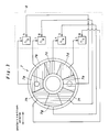
- a light emitting/receiving unit 5 serving as optical identification means is provided in the card reader/writer so as to oppose the identification element 3 as the card 1 is conveyed.
- the light emitting/receiving unit 5 comprises a light emitting device 6 for impinging a laser light beam, consisting of a linearly polarized light of a specific wavelength and a specific polarization direction and serving as detection light, upon the identification element 3 on the surface 1a of the card 1, and an annular light receiving device 7 surrounding the light emitting device 6 ( Figure 2).
- the light receiving device 7 comprises a multi-segment photodiode which is separated into eight segments 7a through 7h, each capable of individually detecting light.
- This light receiving device 7 is connected to a determination unit 8 comprising a CPU, memory, and I/F for determining the authenticity of the card 1.
- the surfaces of the segments 7e through 7h are covered by a first filter 9a which transmits only the linearly polarized light having a prescribed direction of polarization while the surfaces of the segments 7a through 7d are covered by a second filter 9b which transmits only the linearly polarized light whose plane of polarization is rotated by 90 degrees from the mentioned prescribed direction.
- a first filter 9a which transmits only the linearly polarized light having a prescribed direction of polarization
- a second filter 9b which transmits only the linearly polarized light whose plane of polarization is rotated by 90 degrees from the mentioned prescribed direction.
- the identification element 3 comprises a hologram layer 11 consisting of a hologram forming layer 11a and an underlying reflective layer 11b, a bonding layer 12 bonding the hologram layer 11 to the surface 1a of the card 1, and a protective layer 13 covering the surface of the hologram layer 11.
- the material of the hologram forming layer 11a in this case consists of polyvinylchloride (PVC), which has a relatively pronounced double refractive property.
- the thickness of the hologram forming layer 11a is determined such that the double refraction achieved by the hologram forming layer 11a corresponds to one quarter of the wavelength of the laser light radiated from the light emitting device 6.
- the laser light impinged upon the identification element 3 passes through the hologram forming layer 11a twice, and is therefore emitted from the hologram forming layer 11a in the direction determined by the diffractive property of the hologram as a linearly polarized light whose plane of polarization is rotated by 90 degrees or whose phase is shifted by 180 degrees.
- the light is subjected to double refraction by the hologram forming layer 11a, and the light diffracted and reflected by the light reflecting layer 11b is projected upon a prescribed pair of diagonally opposing segments (segments 7a and 7e, segments 7b and 7f, segments 7c and 7g, and segments 7d and 7h) of the light receiving device 7 with respect to the optical axial line of the detection light as a linearly polarized light whose plane of polarization is rotated by 90 degrees from that of the incident light according to the diffractive property of the hologram.
- the segments 7e through 7h of the light receiving device 7 are covered by a first filter 9a which transmits only a linearly polarized light having a polarization plane of a prescribed direction while the segments 7a through 7d of the light receiving device 7 are covered by a second filter 9b which transmits only a linearly polarized light having a polarization plane which is rotated by 90 degrees from the prescribed direction.
- a first filter 9a which transmits only a linearly polarized light having a polarization plane of a prescribed direction
- a second filter 9b which transmits only a linearly polarized light having a polarization plane which is rotated by 90 degrees from the prescribed direction.
- the determination unit 8 determines the ratio of the intensities of the light received by each pair of the segments symmetric with respect to the light emitting device 6, and by comparing each of thus obtained ratios with a prescribed threshold value or by comparing the ratios with one another, the authenticity of the identification element 3 or the authenticity of the card 1 may be determined.
- the difference in the intensities of the light received by the segments 7a and 7e is maximized.
- the ratio of the intensities of the light received by the segments 7a and 7e is maximized as illustrated in Figure 5.
- the lights received by the segments 7a and 7e have a polarization phase shift of 180 degrees between them or, in other words, there is a difference of 90 degrees between the polarization planes of these two lights, and the segments 7a and 7e each have a selective sensitivity to light of the corresponding angle of the polarization plane.
- the overall effect is that the light receiving element has a high selectivity toward the prescribed combination of the diffractive property and polarization plane rotating property of the identification element, and can positively and reliably identify the authenticity of the identification element without being interfered by noises.
- the same result can be achieved, even if the hologram forming layer 11a is not made of material having any particularly pronounced property of double refraction, by providing a polarization plane rotating layer over the surface of the identification element for shifting the phase by the required amount. It is thus conceivable to provide a polarization plane rotating layer in the form of a sticker, and place it over the surface of the identification element for illicit purposes.
- the diffractive property of the identification element 3 and the angle of rotation of the polarization plane achieved by the polarization plane rotating layer do not accurately match with each other, for instance, when diffraction light is directed upon the segments 7a and 7e, since it is necessary that the intensity of the light received by the segment 7e is high while that by the segment 7a is low, and it can be achieved only if the lights received by the segments 7a and 7e have polarization planes of prescribed angles which are 90 degrees apart or a shift difference of 180 degrees, it is readily possible to detect any forgery which involves some errors in the angles of the polarization planes from the corresponding segments of the light receiving device 7. Thus, such an attempt to forge an identification element can be readily detected, and is therefore successfully discouraged.
- the hologram forming layer 11a of the present embodiment is made of a material having a pronounced property of double refraction, but a similar result can be obtained even when the protective layer 13, instead of the hologram forming layer 11a, is made of such a material.
- the material may consist of cellophane, polyvinyl alcohol (PVA), cellulose acetate, polycarbonate resin, and so forth, and can be processed so that the amount of double refraction may correspond to one quarter of the wavelength of the radiated light.
- the object is provided with an identification element which reflects linearly polarized light of a prescribed wavelength into a plurality of point symmetric directions and includes a polarization plane rotating layer for rotating the linearly polarized light by 90 degrees.
- the light from the identification element is received by a prescribed pair of light receiving segments, one of each pair being provided with a first filter transmitting only the light whose plane of polarization is rotated by 90 degrees, while the other of each pair is provided with a second filter transmitting only the light whose plane of polarization is not rotated, so that the authenticity of the object may be determined from the ratio of the intensities of the light received by each pair of the light receiving segments.
- the present invention is highly effective in discouraging the unauthorized duplication of the object.
Landscapes
- Physics & Mathematics (AREA)
- General Physics & Mathematics (AREA)
- Engineering & Computer Science (AREA)
- Theoretical Computer Science (AREA)
- Electromagnetism (AREA)
- General Health & Medical Sciences (AREA)
- Artificial Intelligence (AREA)
- Computer Vision & Pattern Recognition (AREA)
- Toxicology (AREA)
- Health & Medical Sciences (AREA)
- Credit Cards Or The Like (AREA)
- Holo Graphy (AREA)
- Control Of Vending Devices And Auxiliary Devices For Vending Devices (AREA)
- Image Input (AREA)
Claims (8)
- Système d'identification d'un objet (1) comprenant :
un élément d'identification (3) comprenant :
une couche réfléchissante (llb) fixée audit objet (1), ladite couche réfléchissante (llb) ayant une directivité de réflexion telle que, lorsqu'un faisceau de lumière incidente est envoyé sur elle, la lumière réfléchie est envoyée dans au moins deux directions qui sont écartées de 180 degrés autour dudit faisceau incident, et une couche (11a) de rotation du plan de polarisation placée sur ladite couche réfléchissante (llb) pour faire tourner un plan de polarisation de la lumière émise par ladite couche réfléchissante de 90 degrés par rapport audit faisceau de lumière incidente ;des moyens (6) d'émission de lumière pour produire ledit faisceau de lumière incidente sous la forme d'un faisceau de lumière à polarisation linéaire ayant une longueur d'onde prédéterminée et un plan de polarisation prédéterminé ;des moyens (7) de réception de lumière consistant en une pluralité de paires de segments (7a, 7b, 7c, 7d, 7e, 7f, 7g, 7h) détecteurs de lumière agencés à 180 degrés autour dudit faisceau de lumière ;un premier filtre (9a) placé sur un élément de chaque paire desàits segments de réception de lumière, ledit premier filtre (9a) étant adapté pour ne transmettre pour l'essentiel que la lumière émise par ledit élément d'identification (3) dont le plan de polarisation est tourné par ladite couche de rotation du plan de polarisation (11a) ;un deuxième filtre (9b) placé sur l'autre élément de chaque paire de segments de réception de lumière, ledit deuxième filtre (9b) étant adapté pour ne transmettre que la lumière émise par ledit élément d'identification (3) dont le plan de polarisation n'est pas tourné par ladite couche de rotation du plan de polarisation (11a) ; etdes moyens de détermination (8) pour comparer les intensités de lumière détectées par lesdits segments de réception de lumière et déterminer l'authenticité dudit objet (1) selon un motif d'intensités de lumière détecté par lesdits segments de réception de lumière. - Système d'identification d'un objet selon la revendication 1, dans lequel ladite couche réfléchissante (llb) comprend un hologramme, un réseau de diffraction, ou une multiplicité de rainures parallèles en U ou en V ayant une propriété de diffraction unique ou une directivité de réflexion unique.
- Système d'identification d'un objet selon la revendication 1, dans lequel ledit objet (1) consiste en une carte de stockage d'informations convenant pour échanger des informations via un dispositif de lecture/écriture.
- Système d'identification d'un objet selon la revendication 1, dans lequel lesdits moyens de détermination (8) sont munis de moyens pour calculer un rapport des intensités de lumière reçues par chaque paire desdits segments récepteurs de lumière diamétralement opposés (7a-7h), et déterminer l'authenticité dudit objet (1) seulement lorsque ledit rapport est supérieur à un niveau seuil prescrit seulement pour une paire prescrite desdits segments récepteurs de lumière.
- Système d'identification d'un objet selon la revendication 1, dans lequel lesdits moyens de détermination (8) sont munis de moyens pour calculer une différence des intensités de lumière reçues par chaque paire desdits segments récepteurs de lumière diamétralement opposés (7a-7h), et déterminer l'authenticité dudit objet (1) seulement lorsque ladite différence est supérieure à un niveau seuil prescrit seulement pour une paire prescrite desdits segments récepteurs de lumière.
- Système d'identification d'un objet selon la revendication 1, dans lequel lesdits segments détecteurs de lumière (7a-7h) sont agencés autour desdits moyens de réception de lumière (7) d'une manière annulaire, et ledit premier filtre (9a) est placé sur ceux desdits segments détecteurs de lumière qui sont situés sur un côté d'une ligne diamétrale séparant lesdits segments détecteurs de lumière en deux parties égales, tandis que ledit deuxième filtre (9b) est placé sur ceux desdits segments détecteurs de lumière qui sont situés de l'autre côté de ladite ligne diamétrale.
- Système d'identification d'un objet selon la revendication 1, dans lequel ladite couche (11a) de rotation du plan de polarisation se compose d'un hologramme ou d'un réseau de diffraction formée sur une surface inférieure de celle-ci, et munie de la propriété de double réfraction qui est nécessaire pour faire tourner le plan de polarisation de 90 degrés.
- Système d'identification d'un objet selon la revendication 1, dans lequel ladite couche (11a) de rotation du plan de polarisation consiste en une couche protectrice placée sur ladite couche réfléchissante (11b).
Applications Claiming Priority (2)
| Application Number | Priority Date | Filing Date | Title |
|---|---|---|---|
| JP285270/92 | 1992-09-29 | ||
| JP4285270A JPH0797388B2 (ja) | 1992-09-29 | 1992-09-29 | 対象物の識別構造 |
Publications (3)
| Publication Number | Publication Date |
|---|---|
| EP0590826A2 EP0590826A2 (fr) | 1994-04-06 |
| EP0590826A3 EP0590826A3 (en) | 1994-08-24 |
| EP0590826B1 true EP0590826B1 (fr) | 1998-07-01 |
Family
ID=17689332
Family Applications (1)
| Application Number | Title | Priority Date | Filing Date |
|---|---|---|---|
| EP93307235A Expired - Lifetime EP0590826B1 (fr) | 1992-09-29 | 1993-09-14 | Dispositif pour identifier un objet |
Country Status (4)
| Country | Link |
|---|---|
| US (1) | US5497227A (fr) |
| EP (1) | EP0590826B1 (fr) |
| JP (1) | JPH0797388B2 (fr) |
| DE (1) | DE69319396T2 (fr) |
Cited By (7)
| Publication number | Priority date | Publication date | Assignee | Title |
|---|---|---|---|---|
| CN100476465C (zh) * | 2003-05-06 | 2009-04-08 | 史蒂夫·马格鲁 | 光学可变的形态双折射结构和方法及其读取系统和方法 |
| US7812935B2 (en) | 2005-12-23 | 2010-10-12 | Ingenia Holdings Limited | Optical authentication |
| US7853792B2 (en) | 2004-03-12 | 2010-12-14 | Ingenia Holdings Limited | Authenticity verification methods, products and apparatuses |
| US8078875B2 (en) | 2005-07-27 | 2011-12-13 | Ingenia Holdings Limited | Verification of authenticity |
| US8103046B2 (en) | 2004-08-13 | 2012-01-24 | Ingenia Holdings Limited | Authenticity verification of articles using a database |
| US8615475B2 (en) | 2008-12-19 | 2013-12-24 | Ingenia Holdings Limited | Self-calibration |
| US8896885B2 (en) | 2004-03-12 | 2014-11-25 | Ingenia Holdings Limited | Creating authenticatable printed articles and subsequently verifying them based on scattered light caused by surface structure |
Families Citing this family (54)
| Publication number | Priority date | Publication date | Assignee | Title |
|---|---|---|---|---|
| US6019287A (en) * | 1993-10-06 | 2000-02-01 | 3M Innovative Properties Company | Security reader for automatic detection of tampering and alteration |
| US5880826A (en) | 1997-07-01 | 1999-03-09 | L J Laboratories, L.L.C. | Apparatus and method for measuring optical characteristics of teeth |
| US6239868B1 (en) | 1996-01-02 | 2001-05-29 | Lj Laboratories, L.L.C. | Apparatus and method for measuring optical characteristics of an object |
| US5966205A (en) * | 1997-07-01 | 1999-10-12 | Lj Laboratories, Llc | Method and apparatus for detecting and preventing counterfeiting |
| US6307629B1 (en) | 1997-08-12 | 2001-10-23 | Lj Laboratories, L.L.C. | Apparatus and method for measuring optical characteristics of an object |
| US6373573B1 (en) * | 2000-03-13 | 2002-04-16 | Lj Laboratories L.L.C. | Apparatus for measuring optical characteristics of a substrate and pigments applied thereto |
| US5759030A (en) | 1996-01-02 | 1998-06-02 | Lj Laboratories, L.L.C. | Method for determing optical characteristics of teeth |
| US6254385B1 (en) * | 1997-01-02 | 2001-07-03 | Lj Laboratories, Llc | Apparatus and method for measuring optical characteristics of teeth |
| US6118521A (en) * | 1996-01-02 | 2000-09-12 | Lj Laboratories, L.L.C. | Apparatus and method for measuring optical characteristics of an object |
| WO1998010324A1 (fr) * | 1996-09-04 | 1998-03-12 | Electrowatt Technology Innovation Ag | Motifs superficiels presentant au moins deux structures en relief a diffraction lumineuse pour elements de securite optiques |
| US6233047B1 (en) | 1997-01-02 | 2001-05-15 | Lj Laboratories, L.L.C. | Apparatus and method for measuring optical characteristics of an object |
| US6301004B1 (en) | 2000-05-31 | 2001-10-09 | Lj Laboratories, L.L.C. | Apparatus and method for measuring optical characteristics of an object |
| GB2322443A (en) * | 1997-02-24 | 1998-08-26 | Secr Defence | Recognition system for verifying an identifier on an article |
| CH693693A5 (de) | 1997-06-06 | 2003-12-15 | Ovd Kinegram Ag | Vorrichtung zum Erkennen beugungsoptischer Markierungen. |
| US6271913B1 (en) | 1997-07-01 | 2001-08-07 | Lj Laboratories, Llc | Apparatus and method for measuring optical characteristics of an object |
| US6449041B1 (en) | 1997-07-01 | 2002-09-10 | Lj Laboratories, Llc | Apparatus and method for measuring optical characteristics of an object |
| US6501542B2 (en) * | 1998-06-30 | 2002-12-31 | Lj Laboratories, Llc | Apparatus and method for measuring optical characteristics of an object |
| US6870616B2 (en) * | 1998-06-30 | 2005-03-22 | Jjl Technologies Llc | Spectrometer apparatus for determining an optical characteristic of an object or material having one or more sensors for determining a physical position or non-color property |
| US6155491A (en) | 1998-05-29 | 2000-12-05 | Welch Allyn Data Collection, Inc. | Lottery game ticket processing apparatus |
| US6246479B1 (en) | 1998-06-08 | 2001-06-12 | Lj Laboratories, L.L.C. | Integrated spectrometer assembly and methods |
| US6246471B1 (en) | 1998-06-08 | 2001-06-12 | Lj Laboratories, Llc | Apparatus and method for measuring optical characteristics of an object |
| US6573984B2 (en) * | 1998-06-30 | 2003-06-03 | Lj Laboratories Llc | Apparatus and method for measuring optical characteristics of teeth |
| US6249348B1 (en) * | 1998-11-23 | 2001-06-19 | Lj Laboratories, L.L.C. | Integrated spectrometer assembly and methods |
| US6538726B2 (en) | 1998-07-10 | 2003-03-25 | Lj Laboratories, Llc | Apparatus and method for measuring optical characteristics of an object |
| US6628439B2 (en) * | 1998-08-27 | 2003-09-30 | Nippon Mitsubishi Oil Corporation | Genuineness detecting system and method for using genuineness detecting film |
| JP4336008B2 (ja) * | 1998-11-17 | 2009-09-30 | 日本発條株式会社 | 対象物の識別構造及び識別方法 |
| DE19904282C2 (de) * | 1999-02-03 | 2002-05-29 | Xetos Ag | Informationsträger |
| GB9912081D0 (en) * | 1999-05-25 | 1999-07-21 | Secr Defence Brit | Multilayer surface |
| US6362888B1 (en) | 1999-12-23 | 2002-03-26 | Lj Laboratories, L.L.C. | Spectrometer assembly |
| US6519037B2 (en) | 1999-12-23 | 2003-02-11 | Lj Laboratories, Llc | Spectrometer having optical unit including a randomized fiber optic implement |
| US6414750B2 (en) | 2000-01-10 | 2002-07-02 | Lj Laboratories, L.L.C. | Spectrometric apparatus and method for measuring optical characteristics of an object |
| JP2001256670A (ja) * | 2000-03-10 | 2001-09-21 | Sony Corp | 光学ピックアップ装置及び光ディスク装置 |
| DE10146508C2 (de) | 2001-09-21 | 2003-07-24 | Ovd Kinegram Ag Zug | Etikett mit einem diffraktiven Strichcode und Leseanordnung für solche Etiketten |
| US6903813B2 (en) | 2002-02-21 | 2005-06-07 | Jjl Technologies Llc | Miniaturized system and method for measuring optical characteristics |
| DE10207622A1 (de) * | 2002-02-22 | 2003-09-04 | Giesecke & Devrient Gmbh | Sicherheitsdokument und Sicherheitselement für ein Sicherheitsdokument |
| DE60311484T2 (de) * | 2002-08-23 | 2007-10-18 | Tsumura Research Institute Co. | Informationsanzeigegerät und optischer informationsleser |
| US8171567B1 (en) | 2002-09-04 | 2012-05-01 | Tracer Detection Technology Corp. | Authentication method and system |
| RU2268495C1 (ru) * | 2004-06-16 | 2006-01-20 | Сергей Васильевич Андреев | Устройство для идентификации объекта |
| USD516556S1 (en) * | 2004-10-29 | 2006-03-07 | American Bank Note Holographics, Inc. | ABNH hidden image reader |
| US8529560B2 (en) * | 2005-03-04 | 2013-09-10 | The Invention Science Fund I, Llc | Hair treatment system |
| US20060276859A1 (en) * | 2005-06-02 | 2006-12-07 | Searete Llc, A Limited Liability Corporation Of The State Of Delaware | Photopatterning of skin |
| US8157807B2 (en) * | 2005-06-02 | 2012-04-17 | The Invention Science Fund I, Llc | Skin treatment including patterned light |
| US8679101B2 (en) * | 2005-03-04 | 2014-03-25 | The Invention Science Fund I, Llc | Method and system for temporary hair removal |
| US20060200114A1 (en) * | 2005-03-04 | 2006-09-07 | Searete Llc, A Limited Liability Corporation Of State Of Delaware | Hair removal system with light source array |
| US8540701B2 (en) * | 2005-03-04 | 2013-09-24 | The Invention Science Fund I, Llc | Hair treatment system |
| US20070032846A1 (en) * | 2005-08-05 | 2007-02-08 | Bran Ferren | Holographic tattoo |
| US9055958B2 (en) * | 2005-06-29 | 2015-06-16 | The Invention Science Fund I, Llc | Hair modification using converging light |
| US20070038270A1 (en) * | 2005-07-05 | 2007-02-15 | Searete Llc, A Limited Liability Corporation Of The State Of Delaware | Multi step photopatterning of skin |
| US20070048340A1 (en) * | 2005-08-31 | 2007-03-01 | Searete Llc, A Limited Liability Corporation Of The State Of Delaware | Multi step patterning of a skin surface |
| JP4669545B2 (ja) * | 2008-12-08 | 2011-04-13 | 大日本印刷株式会社 | 真正性識別体並びに真正性識別方法及び真正性識別体の製造方法 |
| US20100264227A1 (en) * | 2009-04-21 | 2010-10-21 | Joyce Jared L | Dual Account Transaction Card |
| GB2476226B (en) | 2009-11-10 | 2012-03-28 | Ingenia Holdings Ltd | Optimisation |
| US8840029B2 (en) * | 2012-01-18 | 2014-09-23 | Spectra Systems Corporation | Multi wavelength excitation/emission authentication and detection scheme |
| US10769263B1 (en) | 2019-05-07 | 2020-09-08 | Alibaba Group Holding Limited | Certificate verification |
Family Cites Families (14)
| Publication number | Priority date | Publication date | Assignee | Title |
|---|---|---|---|---|
| ES8204666A1 (es) * | 1980-05-30 | 1982-05-16 | Gao Ges Automation Org | Perfeccionamientos en la fabricacion de papel para billetes de banco y similares |
| CH653161A5 (de) * | 1981-10-27 | 1985-12-13 | Landis & Gyr Ag | Dokument mit einem sicherheitsmerkmal und verfahren zur echtheitspruefung des dokumentes. |
| CH659433A5 (de) * | 1982-10-04 | 1987-01-30 | Landis & Gyr Ag | Dokument mit einem beugungsoptischen sicherheitselement. |
| US4659112A (en) * | 1984-12-03 | 1987-04-21 | Optical Devices, Incorporated | Identification system comprising a partially reflective retardation device |
| CH671371A5 (fr) * | 1986-11-13 | 1989-08-31 | Landis & Gyr Ag | |
| ATE98795T1 (de) * | 1988-09-30 | 1994-01-15 | Landis & Gyr Business Support | Beugungselement. |
| JPH0329050A (ja) * | 1989-06-27 | 1991-02-07 | Nec Corp | 負荷配分方式 |
| US5200794A (en) * | 1989-08-11 | 1993-04-06 | Nhk Spring Co., Ltd. | Optical head for an optical authenticity identifing system |
| US5291006A (en) * | 1989-08-11 | 1994-03-01 | Nhk Spring Co., Ltd. | Authenticity identifying system for information storage cards |
| EP0412316B1 (fr) * | 1989-08-11 | 1996-05-22 | Nhk Spring Company Limited | Système d'identification de l'authenticité pour cartes de stockage d'informations |
| JPH03103964A (ja) * | 1989-09-19 | 1991-04-30 | Fujitsu Ltd | 負荷分散方式 |
| US5095194A (en) * | 1989-10-12 | 1992-03-10 | Joseph Barbanell | Holographic credit card with automatical authentication and verification |
| JP2561186B2 (ja) * | 1991-09-11 | 1996-12-04 | 日本発条株式会社 | 対象物の識別構造 |
| JPH07111726B2 (ja) * | 1991-12-26 | 1995-11-29 | 日本発条株式会社 | 対象物の識別構造及び識別体 |
-
1992
- 1992-09-29 JP JP4285270A patent/JPH0797388B2/ja not_active Expired - Lifetime
-
1993
- 1993-08-16 US US08/122,265 patent/US5497227A/en not_active Expired - Lifetime
- 1993-09-14 EP EP93307235A patent/EP0590826B1/fr not_active Expired - Lifetime
- 1993-09-14 DE DE69319396T patent/DE69319396T2/de not_active Expired - Lifetime
Cited By (12)
| Publication number | Priority date | Publication date | Assignee | Title |
|---|---|---|---|---|
| CN100476465C (zh) * | 2003-05-06 | 2009-04-08 | 史蒂夫·马格鲁 | 光学可变的形态双折射结构和方法及其读取系统和方法 |
| US7853792B2 (en) | 2004-03-12 | 2010-12-14 | Ingenia Holdings Limited | Authenticity verification methods, products and apparatuses |
| US8421625B2 (en) | 2004-03-12 | 2013-04-16 | Ingenia Holdings Limited | System and method for article authentication using thumbnail signatures |
| US8502668B2 (en) | 2004-03-12 | 2013-08-06 | Ingenia Holdings Limited | System and method for article authentication using blanket illumination |
| US8749386B2 (en) | 2004-03-12 | 2014-06-10 | Ingenia Holdings Limited | System and method for article authentication using signatures |
| US8757493B2 (en) | 2004-03-12 | 2014-06-24 | Ingenia Holdings Limited | System and method for article authentication using encoded signatures |
| US8896885B2 (en) | 2004-03-12 | 2014-11-25 | Ingenia Holdings Limited | Creating authenticatable printed articles and subsequently verifying them based on scattered light caused by surface structure |
| US8103046B2 (en) | 2004-08-13 | 2012-01-24 | Ingenia Holdings Limited | Authenticity verification of articles using a database |
| US8078875B2 (en) | 2005-07-27 | 2011-12-13 | Ingenia Holdings Limited | Verification of authenticity |
| US7812935B2 (en) | 2005-12-23 | 2010-10-12 | Ingenia Holdings Limited | Optical authentication |
| US8497983B2 (en) | 2005-12-23 | 2013-07-30 | Ingenia Holdings Limited | Optical authentication |
| US8615475B2 (en) | 2008-12-19 | 2013-12-24 | Ingenia Holdings Limited | Self-calibration |
Also Published As
| Publication number | Publication date |
|---|---|
| JPH06111008A (ja) | 1994-04-22 |
| DE69319396T2 (de) | 1998-10-29 |
| EP0590826A3 (en) | 1994-08-24 |
| JPH0797388B2 (ja) | 1995-10-18 |
| EP0590826A2 (fr) | 1994-04-06 |
| DE69319396D1 (de) | 1998-08-06 |
| US5497227A (en) | 1996-03-05 |
Similar Documents
| Publication | Publication Date | Title |
|---|---|---|
| EP0590826B1 (fr) | Dispositif pour identifier un objet | |
| EP0568185B1 (fr) | Système d'identification d'authenticité d'un article | |
| EP0531605B1 (fr) | Plaque d'identification optique transparent | |
| US5442433A (en) | Identification system for an article having individually attached patches | |
| US6301047B1 (en) | System for optically identifying an object | |
| US4211918A (en) | Method and device for identifying documents | |
| US5461239A (en) | Method and apparatus for coding and reading information in diffraction gratings using the divergence of diffracted light beams | |
| US6019287A (en) | Security reader for automatic detection of tampering and alteration | |
| US20010005570A1 (en) | Multi-layer assembly and method for marking articles and resulting marked articles | |
| EP0552564B1 (fr) | Structure pour identifier l'authenticité d'un article | |
| JPH07210071A (ja) | 対象物の識別システム | |
| JPH11151877A (ja) | 対象物の識別用媒体及び識別構造及び識別方法 | |
| EP0412316B1 (fr) | Système d'identification de l'authenticité pour cartes de stockage d'informations | |
| CA2173230C (fr) | Lecteur de securite pour la detection automatique de falsifications et d'alterations | |
| JPH11277957A (ja) | 紙状対象物の識別構造及び識別方法 | |
| KR940011671B1 (ko) | 정보 저장 카드용 진정성 확인 시스템 | |
| EP0568186A2 (fr) | Système d'identification d'articles | |
| US20220048309A1 (en) | Retroreflective element having a security element | |
| JPH1115380A (ja) | 識別マーク、マーク識別方法及びマーク識別装置 | |
| EP0582756A1 (fr) | Carte à mémoire magnétique | |
| HK1013873B (en) | Security reader for automatic detection of tampering and alteration |
Legal Events
| Date | Code | Title | Description |
|---|---|---|---|
| PUAI | Public reference made under article 153(3) epc to a published international application that has entered the european phase |
Free format text: ORIGINAL CODE: 0009012 |
|
| AK | Designated contracting states |
Kind code of ref document: A2 Designated state(s): DE FR GB |
|
| PUAL | Search report despatched |
Free format text: ORIGINAL CODE: 0009013 |
|
| AK | Designated contracting states |
Kind code of ref document: A3 Designated state(s): DE FR GB |
|
| 17P | Request for examination filed |
Effective date: 19941209 |
|
| 17Q | First examination report despatched |
Effective date: 19970407 |
|
| GRAG | Despatch of communication of intention to grant |
Free format text: ORIGINAL CODE: EPIDOS AGRA |
|
| GRAG | Despatch of communication of intention to grant |
Free format text: ORIGINAL CODE: EPIDOS AGRA |
|
| GRAH | Despatch of communication of intention to grant a patent |
Free format text: ORIGINAL CODE: EPIDOS IGRA |
|
| GRAH | Despatch of communication of intention to grant a patent |
Free format text: ORIGINAL CODE: EPIDOS IGRA |
|
| GRAA | (expected) grant |
Free format text: ORIGINAL CODE: 0009210 |
|
| AK | Designated contracting states |
Kind code of ref document: B1 Designated state(s): DE FR GB |
|
| REF | Corresponds to: |
Ref document number: 69319396 Country of ref document: DE Date of ref document: 19980806 |
|
| ET | Fr: translation filed | ||
| PLBE | No opposition filed within time limit |
Free format text: ORIGINAL CODE: 0009261 |
|
| STAA | Information on the status of an ep patent application or granted ep patent |
Free format text: STATUS: NO OPPOSITION FILED WITHIN TIME LIMIT |
|
| 26N | No opposition filed | ||
| REG | Reference to a national code |
Ref country code: GB Ref legal event code: IF02 |
|
| PGFP | Annual fee paid to national office [announced via postgrant information from national office to epo] |
Ref country code: FR Payment date: 20110922 Year of fee payment: 19 Ref country code: DE Payment date: 20110907 Year of fee payment: 19 Ref country code: GB Payment date: 20110914 Year of fee payment: 19 |
|
| GBPC | Gb: european patent ceased through non-payment of renewal fee |
Effective date: 20120914 |
|
| REG | Reference to a national code |
Ref country code: FR Ref legal event code: ST Effective date: 20130531 |
|
| REG | Reference to a national code |
Ref country code: DE Ref legal event code: R119 Ref document number: 69319396 Country of ref document: DE Effective date: 20130403 |
|
| PG25 | Lapsed in a contracting state [announced via postgrant information from national office to epo] |
Ref country code: DE Free format text: LAPSE BECAUSE OF NON-PAYMENT OF DUE FEES Effective date: 20130403 Ref country code: GB Free format text: LAPSE BECAUSE OF NON-PAYMENT OF DUE FEES Effective date: 20120914 |
|
| PG25 | Lapsed in a contracting state [announced via postgrant information from national office to epo] |
Ref country code: FR Free format text: LAPSE BECAUSE OF NON-PAYMENT OF DUE FEES Effective date: 20121001 |