EP0590833A1 - Système de nettoyage automatique pour rouleaux et cylindres d'imprimerie - Google Patents
Système de nettoyage automatique pour rouleaux et cylindres d'imprimerie Download PDFInfo
- Publication number
- EP0590833A1 EP0590833A1 EP93307386A EP93307386A EP0590833A1 EP 0590833 A1 EP0590833 A1 EP 0590833A1 EP 93307386 A EP93307386 A EP 93307386A EP 93307386 A EP93307386 A EP 93307386A EP 0590833 A1 EP0590833 A1 EP 0590833A1
- Authority
- EP
- European Patent Office
- Prior art keywords
- blade assembly
- blade
- tray
- printing press
- sheathing
- Prior art date
- Legal status (The legal status is an assumption and is not a legal conclusion. Google has not performed a legal analysis and makes no representation as to the accuracy of the status listed.)
- Granted
Links
- 238000004140 cleaning Methods 0.000 title claims abstract description 38
- 239000000463 material Substances 0.000 claims abstract description 61
- 238000007639 printing Methods 0.000 claims abstract description 43
- 238000005406 washing Methods 0.000 claims abstract description 31
- 239000007788 liquid Substances 0.000 claims abstract description 16
- 239000007787 solid Substances 0.000 claims abstract description 16
- 230000002745 absorbent Effects 0.000 claims abstract description 13
- 239000002250 absorbent Substances 0.000 claims abstract description 13
- 238000007790 scraping Methods 0.000 claims abstract description 5
- 239000002991 molded plastic Substances 0.000 claims 1
- 239000002904 solvent Substances 0.000 abstract description 56
- 230000006872 improvement Effects 0.000 abstract description 4
- 238000000034 method Methods 0.000 abstract description 3
- 230000001681 protective effect Effects 0.000 abstract description 2
- 239000000976 ink Substances 0.000 description 72
- 239000007921 spray Substances 0.000 description 10
- 239000012530 fluid Substances 0.000 description 9
- 239000000123 paper Substances 0.000 description 9
- 229920002799 BoPET Polymers 0.000 description 8
- 239000005041 Mylar™ Substances 0.000 description 8
- 239000004744 fabric Substances 0.000 description 7
- 239000004033 plastic Substances 0.000 description 7
- 229920003023 plastic Polymers 0.000 description 7
- 230000001276 controlling effect Effects 0.000 description 6
- 229920001971 elastomer Polymers 0.000 description 5
- 239000005060 rubber Substances 0.000 description 5
- 238000004873 anchoring Methods 0.000 description 4
- 230000008901 benefit Effects 0.000 description 4
- 238000011109 contamination Methods 0.000 description 4
- 230000004048 modification Effects 0.000 description 4
- 238000012986 modification Methods 0.000 description 4
- 239000000126 substance Substances 0.000 description 4
- 229910000831 Steel Inorganic materials 0.000 description 3
- -1 debris Substances 0.000 description 3
- 239000010959 steel Substances 0.000 description 3
- 239000004698 Polyethylene Substances 0.000 description 2
- 239000000701 coagulant Substances 0.000 description 2
- 239000000356 contaminant Substances 0.000 description 2
- 230000002939 deleterious effect Effects 0.000 description 2
- 229920003223 poly(pyromellitimide-1,4-diphenyl ether) Polymers 0.000 description 2
- 229920000573 polyethylene Polymers 0.000 description 2
- 229920000642 polymer Polymers 0.000 description 2
- 229920001343 polytetrafluoroethylene Polymers 0.000 description 2
- 239000004810 polytetrafluoroethylene Substances 0.000 description 2
- 239000002910 solid waste Substances 0.000 description 2
- 125000000391 vinyl group Chemical group [H]C([*])=C([H])[H] 0.000 description 2
- 229920002554 vinyl polymer Polymers 0.000 description 2
- 239000004809 Teflon Substances 0.000 description 1
- 229920006362 Teflon® Polymers 0.000 description 1
- ATJFFYVFTNAWJD-UHFFFAOYSA-N Tin Chemical compound [Sn] ATJFFYVFTNAWJD-UHFFFAOYSA-N 0.000 description 1
- 238000005299 abrasion Methods 0.000 description 1
- 230000009471 action Effects 0.000 description 1
- 238000007792 addition Methods 0.000 description 1
- 229910052782 aluminium Inorganic materials 0.000 description 1
- XAGFODPZIPBFFR-UHFFFAOYSA-N aluminium Chemical compound [Al] XAGFODPZIPBFFR-UHFFFAOYSA-N 0.000 description 1
- 239000011538 cleaning material Substances 0.000 description 1
- 238000010276 construction Methods 0.000 description 1
- 230000009849 deactivation Effects 0.000 description 1
- 230000006735 deficit Effects 0.000 description 1
- 239000000428 dust Substances 0.000 description 1
- 230000000694 effects Effects 0.000 description 1
- 239000007789 gas Substances 0.000 description 1
- 230000002401 inhibitory effect Effects 0.000 description 1
- 239000010808 liquid waste Substances 0.000 description 1
- 239000000314 lubricant Substances 0.000 description 1
- 230000007246 mechanism Effects 0.000 description 1
- 229910052751 metal Inorganic materials 0.000 description 1
- 239000002184 metal Substances 0.000 description 1
- 150000002739 metals Chemical class 0.000 description 1
- 239000000203 mixture Substances 0.000 description 1
- 238000007645 offset printing Methods 0.000 description 1
- 230000001105 regulatory effect Effects 0.000 description 1
- 238000010186 staining Methods 0.000 description 1
- 239000002699 waste material Substances 0.000 description 1
Images




Classifications
-
- B—PERFORMING OPERATIONS; TRANSPORTING
- B41—PRINTING; LINING MACHINES; TYPEWRITERS; STAMPS
- B41F—PRINTING MACHINES OR PRESSES
- B41F35/00—Cleaning arrangements or devices
- B41F35/06—Cleaning arrangements or devices for offset cylinders
-
- B—PERFORMING OPERATIONS; TRANSPORTING
- B41—PRINTING; LINING MACHINES; TYPEWRITERS; STAMPS
- B41F—PRINTING MACHINES OR PRESSES
- B41F35/00—Cleaning arrangements or devices
-
- B—PERFORMING OPERATIONS; TRANSPORTING
- B41—PRINTING; LINING MACHINES; TYPEWRITERS; STAMPS
- B41F—PRINTING MACHINES OR PRESSES
- B41F35/00—Cleaning arrangements or devices
- B41F35/006—Cleaning arrangements or devices for impression cylinders
-
- B—PERFORMING OPERATIONS; TRANSPORTING
- B41—PRINTING; LINING MACHINES; TYPEWRITERS; STAMPS
- B41F—PRINTING MACHINES OR PRESSES
- B41F35/00—Cleaning arrangements or devices
- B41F35/02—Cleaning arrangements or devices for forme cylinders
-
- B—PERFORMING OPERATIONS; TRANSPORTING
- B41—PRINTING; LINING MACHINES; TYPEWRITERS; STAMPS
- B41F—PRINTING MACHINES OR PRESSES
- B41F35/00—Cleaning arrangements or devices
- B41F35/04—Cleaning arrangements or devices for inking rollers
-
- B—PERFORMING OPERATIONS; TRANSPORTING
- B41—PRINTING; LINING MACHINES; TYPEWRITERS; STAMPS
- B41P—INDEXING SCHEME RELATING TO PRINTING, LINING MACHINES, TYPEWRITERS, AND TO STAMPS
- B41P2235/00—Cleaning
- B41P2235/10—Cleaning characterised by the methods or devices
- B41P2235/20—Wiping devices
- B41P2235/24—Wiping devices using rolls of cleaning cloth
- B41P2235/242—Unwinding the cleaning cloth
-
- B—PERFORMING OPERATIONS; TRANSPORTING
- B41—PRINTING; LINING MACHINES; TYPEWRITERS; STAMPS
- B41P—INDEXING SCHEME RELATING TO PRINTING, LINING MACHINES, TYPEWRITERS, AND TO STAMPS
- B41P2235/00—Cleaning
- B41P2235/10—Cleaning characterised by the methods or devices
- B41P2235/20—Wiping devices
- B41P2235/24—Wiping devices using rolls of cleaning cloth
- B41P2235/246—Pressing the cleaning cloth against the cylinder
Definitions
- This invention relates to an improved cleaning assembly for cleaning solid and liquid debris from the various cylinders and rollers of a printing press, and more particularly, to an improved cleaning assembly for cleaning solid and liquid debris from the blanket cylinder, impression cylinder plate cylinder, or the ink roller train of a printing press, having apparatus for protecting the components of the cleaning assembly from soiling during a washup operation.
- One of the more difficult and time consuming tasks in a printing operation is the need to periodically clean the various printing press rollers and cylinders, such as the blanket cylinder, impression cylinder, plate cylinder and, in particular, the ink rollers (collectively referred to as an "ink roller train") of ink and other debris.
- These cleaning operations are sometimes referred to by those skilled in the art as “washings” or “washup” operations.
- washup operations are needed to remove extraneous paper dust, debris, and other contaminants from the ink roller train to improve the quality of the printed product.
- An ink roller train washup operation is also required when ink color changes are implemented by the press operator.
- Ink roller washings are tedious operations, often requiring significant (and sometimes dangerous) manual intervention on the part of the press operator.
- the print operator will usually "squirt" or otherwise apply a cleaning solvent directly onto the print cylinders and ink roller train.
- the solvent loosens the ink and other debris from the cylinders and ink rollers, which is then scraped off or otherwise removed from the printing press.
- the scraping operation is a messy and time consuming task, and in the past has involved manually wiping the surface of the cylinders and rollers so that the solvent, along with the ink and other solid debris, can be collected in a trough or pan, or alternatively, captured by a rag or some other absorbent material.
- the washup operation may also be performed by devices designed to engage the cylinders or ink rollers and scrape off the ink or other debris.
- Such devices include, for example, inflatable bladders which fill with air or other gases to lightly touch the surface of the cylinder or roller and remove debris.
- Devices using a wiping blade have also been used to scrape debris from cylinders and inking rollers.
- it is frequent that the blade is inadequately cleaned following a washup operation. The result is that the geometry of the blade tip is altered with subsequent washings, lowering both the effectiveness of the blade in cleaning the press rollers, and lessening the effective life expectancy of the blade.
- Figs. 1A and 1B illustrate in perspective a prior embodiment of a press washer system for inking rollers.
- a typical prior art press washer system 10 includes a blade assembly 24 pivotally mounted onto the printing press 14 with a blade unit 12 serving to clean the inking roller train 16.
- the blade assembly 24 is pivoted into engagement with the roller train 16 via a piston actuation means 52 controlled by a solenoid 54.
- the system 10 also includes, for example, one or more spray bars 20 mounted at or near the top end of ink roller train 16.
- the spray bars 20 supply cleaning solvent or fluid onto the ink roller train 16.
- Excess solvent is collected in a spray bar drip pan 22 mounted beneath the spray bars 20, and returned to a collection system (not shown).
- the solvent flows through the individual rollers forming the inking train 16. Through pressing action between the rollers, ink and debris is removed therefrom, flowing to the lower portion of the ink roller train 16.
- the system 10 has the blade assembly 24 pivotally mounted to the press frame at a lower portion of the inking roller train 16.
- the blade assembly 24 removes ink, debris, or other contaminants from the ink roller train 16 during a washings operation, and accumulates such debris in a drip pan or receptacle trough 18.
- the blade unit 12 engages a roller 15 of the inking train 16 to remove the ink and solvent that has been released from the inking train 16.
- the ink and solvent is then collected in the press washer trough 18 for final disposal.
- both the blade unit and trough are unprotected from being stained or soiled by the ink and solvent; are subject to the deleterious effects, such as blade wear, as previously noted; and thus require significant manual operator intervention during and following a washup operation.
- a typical press washer system may also include a controller 40 (shown in Fig. 2) for controlling the operation of the press washer system 10.
- the controller 40 allows a press operator to simultaneously control a plurality of separate press washer systems 10.
- the controller 40 usually includes commercially available software, electronic components and internal circuitry known to those skilled in the art, for controlling the washer systems 10.
- the system controller 40 is operatively connected to an operator control panel 42 having a plurality of keypad inputs for controlling critical features of the systems 10. For example, through use of the keypads, the press operator may enter system parameters and information, including spray wash time, press cleaning time, and other variables that dictate operation of the press washer systems 10.
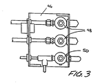
- input connections 45 to the individual washer system 10 are linked through a fluid/air box 46, to control the supply of cleaning solvent and pressurized air from central sources designed to supply a plurality of press washer systems 10.
- the individual fluid/air boxes 46 include one or more solvent valves 48 and an air valve 50 to regulate the supply of solvent fluids and pressurized air to each individual washer system 10.
- the solvent valves 48 are operatively connected to the individual spray bars 20, while the air valve 50 is operatively connected to a piston actuation means 52 (as shown in Fig. 1B) for controlling actuation of the blade assembly 24.
- These valves 48, 50 are individually controlled by solenoids 54 whose operation is controlled by the system controller 40.
- the press operator can control opening and/or closing of the valves 48, 50 by operating the appropriate solenoid 54 through information input into the control panel 42. Entry of this information sends signals to the system controller 40, which controls actuation of the solenoids 54 in the individual air/fluid boxes 46, and regulates the amount and duration of solvent emissions through the spray bars 20 and air emission into the actuation means 50 for controlling actuation of the blade assembly 24 against the roller 15.
- the final aspect of the washup operation entails the collection and disposal of the fluid and solid wastes removed from the inking roller train 16.
- An inherent disadvantage with systems such as those described above comes from the liquid and solid debris that is collected in a tray or pan.
- the pan often forms a permanent fixture of the ink roller washings unit, and has to be painstakingly removed from the printing press in order for the pressman to dispose of the liquid and solid debris collected therein.
- Another disadvantage with systems such as these described above is that none of the system components are protected from.staining by ink, solvent or debris. Upon completion of the washings operation, it is necessary to manually clean the collecting pan, the bladder or blade, and other components of the washings assembly prior to renewing printing operations.
- the device may be employed to clean various of the cylinders found in printing presses known in the art, including the blanket cylinder, impression cylinder and plate cylinders found in offset printing presses.
- the invention is described as applied to the inking cylinders of a printing press, the invention, of course, being equally applicable to the other cylinders as previously noted.
- the improved blade assembly may be employed or configured with various known washings systems as previously described. Other than manual application of the solvent, these washings systems might include one or more spray bars positioned at the top portion of the ink roller train to apply cleaning solvent onto the train to loosen the ink and debris from the rollers. Excess solvent is collected in a drip tray located downstream of the spray bars.
- the improvement to the system includes a blade assembly which is affixed to the press. The improved blade assembly is provided and positioned into and out of engagement with an ink roller to scrape off the ink, excess solvent, and other debris which has been dislodged from the ink roller train.
- the entire blade assembly is pivotally mounted to pressingly engage an inking roller upon command from a system controller.
- the blade assembly has a resilient blade member to scrape debris into a receptacle or trough for collection.
- the blade unit may be protected with a sheathing system to significantly reduce blade wear and prolong its life, while at the same time preventing the blade member from being contaminated or stained during the washings operation.
- the sheathing system may be implemented in a variety of manners.
- the sheathing system is configured as a device feeding a clean portion of a continuous sheath material obtained from a roll supply.
- the sheath material is impervious to liquids, resistant to chemicals, and possesses a low coefficient of friction ( ⁇ ) to enable the blade to slidingly engage any of the rollers which may be encountered in use, without undue scraping or heat build-up.
- ⁇ coefficient of friction
- a take-up roll may be mounted within the confines of the receptacle trough to retract the used portion of the sheath material.
- the supply and take-up rolls are meshingly linked by a mechanism which is actuated either by the pressing engagement of the blade assembly with the inking roller, or when the blade assembly is retracted therefrom.
- the pivoting actuation of the blade assembly automatically advances clean sheath material from the supply roll and retracts used sheath material onto the take-up roll, eliminating the need for additional motors or other devices to advance or retract the sheath material, and relieving the need for manual intervention on the part of the press operator.
- the sheathing system can be configured, for example, as a "slip-on" embodiment which covers the blade; or as a removable shield formed to the contours of the blade member.
- the receptacle trough may be formed as a permanent fixture of the blade assembly, or as an inexpensive removable unit that may be disposed intact with the solvent and ink accumulated therein.
- the trough may be lined with an absorbent wadding to protect the trough from soiling and to absorb the ink and solvent collected from the ink train.
- the blade sheath may extend slightly beyond the blade unit to cover a portion of the interior of the receptacle trough, further protecting the trough from contamination during washings.
- the trough may also be supplemented by or, with modification to the blade assembly, replaced by a disposable bag like insert which is affixed to a frame, and supported on the blade assembly.
- an automatic press washer system according to the present invention.
- the device is described in connection with cleaning the ink roller train of a printing press, it being understood, of course, that the device be employed to clean other rollers or cylinders, such as the plate cylinder, impression cylinder, or blanket cylinder of printing presses.
- an improved blade assembly 60 is pivotally affixed about a fixed stud type pivot 100 attached to the frame 62 of a press, and includes a blade unit 64 for engagement with a bottom most ink roller 72 of the inking roller train 70.
- the blade assembly 60 is generally pivotal between two operative positions. In a first operative position, the blade unit 64 is biased away from the inking roller 72 so that there is no contact between the blade unit 64 and the inking roller 72. In the second operative position, the blade unit 64 is held in contact with the surface of the inking roller 72 to effect cleaning and removal of debris from the inking roller 72.
- Pivoting of the blade assembly 60 between the first and second positions described above is effected by an actuator 65 affixed to the frame 62 of the press that engages the blade assembly 60 to rotate the blade assembly about pivot 100.
- an actuator 65 affixed to the frame 62 of the press that engages the blade assembly 60 to rotate the blade assembly about pivot 100.
- a pneumatic actuator since compressed air is commonly available in press room environments.
- the use of a pneumatic actuator is not critical to the invention, and suitable electrical or hydraulic actuators may also be used in the present invention.
- the blade assembly also features manual actuation means, provided either as an override should actuator 65 fail, or means unto itself for pivoting blade assembly 60 into operative position.
- an actuation knob 150 is rotatably threadedly affixed through the frame 62.
- the knob 150 includes a fixed shaft 152 in engagement with a bracket 154 attached to the blade assembly 60.
- a spring 156 is affixed at either end to the bracket 154 and frame 62.
- the press operator may rotate the knob 150 to cause fixed shaft 152 to press against bracket 154, causing the blade assembly 60 to pivot clockwise about pivot 100 for engaging the blade unit 64 against inking roller 72.
- spring 156 is compressed, and the spring will provide a biasing force to urge the blade assembly 60 counterclockwise about pivot 100 when the operator desires to disengage the blade assembly 60 by rotating knob 150 and shaft 152 in the opposite direction.
- the blade unit 64 includes a length wise blade 66 with a semi rigid pliable member 68 preferably formed of rubber, plastic or the like which actually engages with the lower most inking roller 72 to scrape the solvent and ink therefrom.
- the pliable member 68 is preferably soft enough not to damage the surface of the inking roller 72, but resilient enough to provide rigidity to thoroughly scrape ink, solvent and debris from the roller 72.
- the blade assembly 60 includes a collection tray or trough 80 located below the blade unit 64, and which runs lengthwise parallel to the axis of inking roller 72.
- the collection tray 80 has a generally open end 81 for allowing solvent and ink scraped from the inking roller 72 to enter into the interior of the tray 80 for collection.
- the tray 80 may be affixed, for example, to an L-shaped support 82 forming part of the blade assembly 60.
- the tray 80 preferably has a rectangular cross-section, but it is not so limited. As may be apparent to those skilled in the art, other shapes appropriate to the press design or convenient to the user can be employed to provide the functions described above.
- the tray 80 may be formed from moldable materials, such as steels, plastics, rubbers, vinyls, or from any inexpensive material suitable therefore (for example, formed metals such as aluminum or tin). However, it may also be made from paper materials such as cardboard (preferably coated in its interior with a waterproof substance, such as wax or plastic) when the tray 80 is intended for disposal and not for reuse.
- moldable materials such as steels, plastics, rubbers, vinyls, or from any inexpensive material suitable therefore (for example, formed metals such as aluminum or tin).
- paper materials such as cardboard (preferably coated in its interior with a waterproof substance, such as wax or plastic) when the tray 80 is intended for disposal and not for reuse.
- the tray 80 may be configured as a non-disposable unit, forming a permanent part of the blade assembly 60. As will be later described, the tray 80 may be lined with an absorbent material 93 to protect the interior of the tray from soiling and to collect the dissolved ink/solvent scraped from ink train 70. Thus., the tray 80 may be conveniently prevented from being soiled during the washup operation.
- the tray 80 may be detachable from the blade assembly 60 in manners known to those skilled in the art to permit routine cleaning and reuse. In this manner, once the tray 80 is filled with collected ink and solvent following the washings operation, the pressman may simply release the soiled tray 80 from the support 82 and quickly clean it or replace it with a clean one.
- the soiled tray 80 may be placed aside for later draining of the solvent/ink and cleaning so that it might be re-used.
- the tray 80 may also be formed as a detachable unit that is suitable for disposal once filled with solvent/ink. In this configuration, the soiled tray 80 may be discarded, intact and according to accepted procedures for the disposal of inks and solvents, to rapidly and conveniently dispose of the ink/solvent.
- the L-shaped support 82 pivotal as part of the blade assembly 60, supports the disposable tray 80.
- the disposable tray 80 is substantially configured to the dimensions of the support 82.
- the support 82 may be modified to include a plurality of clips or other devices known to these skilled in the art (not shown) for releasably supporting and attaching the tray 80 in manners known to those in the art.
- the invention includes a sheathing system 170 to protect the blade unit 64 and trough 80 from soiling during the washup operation.
- the material employed for the sheathing system 170 ought to possess a number of basic qualities.
- the material should be heat resistant to withstand the range of operating temperatures (typically 10-150°C) normally encountered in use.
- the sheath material should also possess a relatively low coefficient of friction ( ⁇ ), so that blade 68 will run smoothly and effectively over the surface of the roller 72.
- coefficients of friction will vary depending upon the roller covering (for example, steel, rubber or cloth), and the amount of solvent present (solvent, of course, acting as a lubricant). It is believed that the sheathing material should possess a dynamic ⁇ in the range of 0.10 to 0.40 to enable the blade to smoothly engage the various roller surfaces which may be encountered regardless of the amount of solvent which may be actually present in the system.
- the advantages of a low coefficient are multiple: it prevents excessive heat build up and wear, which would be especially prevalent where there is not enough solvent provided during the washup cycle; it promotes the effective life expectancy of the blade 68; and it deters the blade 68 from accidentally deflecting beneath and getting pulled under by the press rollers, which can occur if there is a deficit of solvent and the friction level is elevated between blade 68 and roller 72.
- sheath material should be relatively thin (i.e., in the range of 0.48-10 mils). A thin material is necessary in order to preserve the geometry of the blade tip 68a to allow the blade 68 to effectively clean the roller 72.
- sheath material Other basic mechanical characteristics for the sheath material include: abrasion resistance; chemical resistance (to withstand the various solvents and chemicals encountered in washup operations); good dimensional stability at elevated temperatures; and good sheer strength. Numerous materials have been tested for the sheath material, including: PTFE film, "Kapton” film, or VHMW polyethylene, all produced by the 3M Corporation; various types of wax type papers, including “freezer wrap”, “deli fresh paper”, and “SnowFibre-Kold Lok Polymer”, all produced by the James River Corporation; and teflon.
- Mylar produced by DuPont Corporation
- Mylar exhibits a dynamic ⁇ of 0.20 for a steel covered roller and 0.28 with a rubber covered roller, well within the ranges believed adequate for effective use as described above.
- the sheathing system 170 may be configured in a number of ways, and it is understood that all embodiments may be used with either a tray 80 forming a permanent part of the blade assembly 60, or with a tray 80 that is intended to be disposable.
- Fig. 4A illustrates an enhanced sectional view of the blade assembly 60 illustrated in Fig. 4 showing a preferred embodiment for automatically actuating the sheathing system 170 upon actuation of blade assembly 60.
- a supply roll 90 of sheath material is inserted about a fixed supply shaft 102 attached to the outside of trough 80.
- the supply roll 90 is free to rotate about supply shaft 102 to supply sheathing material 104 in a manner to be explained hereafter.
- the supply roll 90 may be released from the supply shaft 102, in manners known to those skilled in the art, to permit replacement of used supply rolls 90.
- Affixed to the outside of tray 80 are a pair of gears 105, 110 and a center gear 115.
- the center gear 115 is rotatably affixed about an axle 116 attached to the tray 80 and is meshed with both of the gears 105, 110.
- Center gear 115 is free to rotate in both the clockwise and counterclockwise directions.
- Gear 105 is affixed to a one-way clutch bearing 114 that is disposed about the pivot 100 affixed to the frame 62.
- Gear 110 is affixed to a take-up shaft 120.
- the shaft 120 is rotatably affixed at either end to the sides of tray 80, and extends lengthwise through the interior of tray 80.
- the take-up shaft 120 may be configured in a releasable manner, as known to those in the art, to permit the operator to remove it as need or desire dictate. As shown, one end of take-up shaft 120 is disposed through a clutch bearing 112 journaled in one side wall of tray 80.
- actuator 65 (or, as previously described, manual actuation via knob 150) is activated to rotate blade assembly clockwise about pivot 100.
- the one-way clutch bearing 114 is oriented to lock about pivot 100 during actuation, so that as blade assembly 60 is actuated into position, gear 105 is locked and prevented from rotating about pivot 100. In essence, gear 105 becomes a "locked” gear upon actuation of blade assembly 60. This causes center gear 115 to rotate clockwise, driving gear 110 (and its take-up shaft 120) counterclockwise to reel in previously used sheath material and advance a clean supply of sheathing material 104 from supply roll 90.
- the number of teeth and gearing ratios for each of the gears 105, 110 and 115 may be selected to retract an appropriate length of clean sheathing material from roll supply 90 so that the engaging tip 68a of cleaning blade 68 will be fully sheathed by clean sheath material during a washing operation.
- the minimum length of sheathing material required is approximately one-quarter inch (1 ⁇ 4").
- the device may be configured so that just the required length of sheath material 104 is expended during a washing operation, thus greatly extending the life and usefulness of each sheath supply roll 90.
- Figs. 4b and 4c show an alternate manner for implementing automatic actuation of the sheathing system.
- gear 105 is fixed against rotation to the end of stud 100 attached to frame 62.
- stud 100 travels in an arcuate slot 205 cut through the side wall of tray 80.
- a guide member 200 having a flattened engaging face 200a disposed slidingly flush against the outside surface of tray 80 is affixed to frame 62.
- guide member 200 surrounds the stud 100 to ensure that the center of stud 100 travels along the central arc 205a of arcuate slot 205.
- gear 105 is meshingly engaged to center gear 115, itself meshed with a gear 110.
- center gear 115 is affixed to a pivot axle 116 affixed to the frame 62.
- Pivot axle 116 is free to rotate in a pair of bearings 116a respectively journaled into the frame 62 and the tray 80.
- a one-way bearing clutch 110a is journaled into the gear 110.
- the take-up shaft 120 extends through the one-way bearing clutch 110a and its opposed ends are rotatably supported at respective bearings 120a journaled at either end of tray 80.
- blade assembly 60 is engaged as previously described.
- the blade assembly now pivots about pivot axle 116, and stud 100 is free to travel along the length of slot 205.
- Gear 105 fixed against rotation, drives gear 115 (which is free to rotate).
- Gear 115 drives gear 110 to rotate the take-up roll 120 in the manner previously described.
- the one-way clutch 110a is oriented so that it locks onto the shaft 120 during the actuation phase, thereby transmitting the rotational force exerted upon the gear 110 to the shaft 120.
- Fig. 4D illustrates another manner for implementing automatic actuation of the sheathing system.
- stud 100 is fixed to the frame 62, and it passes through a bearing 100a journaled into the side wall of tray 80.
- a second bearing 100b is disposed at the opposite end of stud 100.
- Bearing 100b is journaled into gear 105.
- a pin 300 fixed to tray 80 has a tooth 300a configured to the gearing dimensions of gear 105. Tooth 300a engages the teeth of gear 105.
- Take-up shaft 120 is rotatably disposed at either end of tray 80 through a pair of bearings 120a journaled into the respective side walls of tray 80.
- the shaft 120 passes through a one-way clutch 110a.
- one-way clutch 110a itself is journaled into gear 110.
- blade assembly 60 is pivotally actuated about stud 100 (bearing 100a allowing the tray 80 to pivot about the stud 100).
- Gear 105 which is free to rotate about bearing 100b, is driven by tooth 300a of fixed pin 300.
- One-way clutch 110a is oriented to lock onto take-up shaft 120 during the actuation phase for the blade assembly. Gear 105 thus drives gear 110 and power is transmitted to take-up shaft 120 to roll up the used sheath-material.
- one-way clutch 110a Upon deactuation of the blade assembly 60, one-way clutch 110a disengages from take-up shaft 120, so that gear 110 is free to rotate about take-up shaft 120. Thus, while pin 300 engages gear 105 to rotate gear 110, power will not be transmitted to take-up shaft 120, preventing used portions of sheath material from being drawn back onto supply roll 90.
- stud 100 may be squared off at its end outside tray 80.
- the squared end could be releasably engaged in a corresponding notch 310 formed in frame 62.
- Such an arrangement would both provide fixation against rotation for stud 100, and allow a convenient means for releasing the blade assembly 60 from the press.
- the various components may be configured so that the gears 105, 110, 115 may be placed either within the interior of tray 80 or outside of the tray 80.
- the tray 80 may be lined with an absorbent wadding 93 formed to the dimensions of the tray to retain and capture used solvent, ink and debris collected from the roller train 70.
- an absorbent wadding 93 formed to the dimensions of the tray to retain and capture used solvent, ink and debris collected from the roller train 70.
- the shape, size, or other dimensions of wadding 93 may be appropriately selected taking into account the placement of any components associated with the sheathing system 170 so as not to interfere with the operation of the sheathing system.
- the wadding 93 may be used in either the permanent or disposable tray 80, and in combination with the various alternate sheathing systems to be subsequently described.
- the wadding 93 should be highly absorbent, able to withstand, for example, a full days operation of a printing press and the attendant repeated washups conducted, so as to eliminate the need to constantly remove the wadding from the tray 80, and to protect the interior of tray 80 from soiling.
- a suitable wadding may be formed, for example, from commercial grade absorbent materials, such as the PIG® absorbent wadding manufactured by the New Pig Corporation of Tipton, Pennsylvania.
- the sheathing system 74 may constitute, for example, a lengthwise bag 71 that is slipped over the blade member 68 prior to any printing operation.
- the slip on bag 71 may be formed to the dimensions of the blade member 68 and blade unit 64.
- the slip on bag 71 while preferably formed of Mylar, may be formed from various plastics, rubber materials, or the like, and serves to cover both the blade member 68 and the blade unit 64 during washings. Following the washup operation, the press operator need simply slip the soiled bag 71 off of the blade member 68 for rapid and convenient disposal.
- both the wearing down of the blade member 68, as well as the deleterious effects suffered by (and the somewhat irritating squeal caused by) a dry blade member 68 contacting the ink roller 72 can be greatly alleviated.
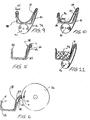
- the sheathing system 74 may be formed as bag like insert 73 (see Fig. 6) which is placed directly into the interior of the tray 80 (which, as previously explained, may constitute either the permanent tray or the disposable tray).
- the bag like insert 73 may be formed substantially to the dimensions of the tray 80 and includes an extended lip portion 75 on one end to extend over and cover blade member 68.
- the bag insert 73 includes longitudinally extending, opposed channels 77 located at one end thereof and extending along the length of the bag insert 73.
- the channels 77 may be formed with a male or female member that corresponds to substantially similar and complimentary male/female channels 79 located of the lip portion 75.
- the two channels 77,79 form an interlocking relationship when press joined together to permit the bag insert 73 to be sealed once it is filled with ink and solvent. This arrangement provides a neat package to simplify disposal of the ink and solvent.
- a plurality of anchoring openings may be formed directly above opposed channels 77,79 to engage with protrusions, clips or other devices (not shown) located within the interior of the tray 80.
- the anchoring openings, together with the protrusions or clips, provide a means of anchoring bag insert 73 to the tray 80.
- the bag insert 73 use of a rigid collecting tray 80 may be eliminated from the blade assembly 60.
- the blade unit 64 is directly affixed to the frame 82.
- the bag is supported within the frame 82 which is pivotally engaged with the press.
- the anchoring openings or clips located on the frame 82, the bag may be securely held open by and supported within the frame 82.
- the frame 82 provides lateral support for the bag insert 73, while the bag insert 73 may be formed from a sufficiently strong material, such as Mylar, to withstand the weight and any forces exerted by the ink/solvent collected therein.
- Fig. 8 illustrates yet another embodiment of a sheathing system 74 according to the invention.
- the sheathing system 74 constitutes a shield 75 molded or formed to the dimensions of the blade member 68.
- the shield 75 includes a curved lip portion 75a which is curved to fit around the blade unit 68, and provides a planar main portion 75b to cover to the bulk of the blade member.
- the shield 75 which is preferably formed of Mylar but not so limited, may be formed from materials such as plastic, vinyl, paper products such as cardboard (which may be coated with a moisture resistant material such as wax or plastic), or other suitable materials.
- the shield 75 may be removed by the press operator for disposal (or if made from a recyclable material, for later cleaning), and replaced by a fresh unit.
- Fig. 9 illustrates a simplified modification of the preferred configuration described in Figs. 4A-D.
- the sheathing material may also be supplied from a roll supply of sheath material 90 located below the receptacle tray 80.
- the roll is rotatably anchored below the tray 80. It is understood that for embodiments employing a disposable tray 80, the roll supply could be anchored below the L-shaped support 82.
- the sheath material 91 is pulled from the roll supply 90 beneath the tray 80 and over the blade member 68 to cover the blade member 68 during the washings operation. Actuation of the blade unit 64 during the cleanup securely traps the sheath 91 between the surface of roller 72 (not shown) and the blade unit 64.
- the sheath 91 is pulled to extend over and to cover the blade member 68 and its associated blade unit 64.
- the sheath 91 can extend to line the interior of tray 80, providing further protection against contamination and debris.
- retaining clips 95 are secured over one edge of the tray 80 so that the sheath 91 may be securely engaged thereon.
- a securing rod 94 as illustrated in Fig. 10, may be placed longitudinally across the length of the tray 80.
- the sheath 91 would be pulled into the interior and threaded between the back wall of the tray 80 and the rod 94. It is, of course, understood that the manners of retaining the sheath 91 within the tray 80 may be employed with all embodiments of tray 80.
- the wadding 93 may also be placed on top of the sheath 91, once it is pulled into the interior of the tray 80, to further protect the tray 80 from contamination.
- a sheath material that includes a multi-surface configuration having an outside surface which is absorbent to liquids such as solvents and ink, and an inside surface contacting the blade member 68 which is impervious to moisture.
- the outside surface of the sheath can absorb the ink and solvent, while the coated inside surface protects the components from being soiled or stained during the washings operation.
- the outside surface should display high wicking characteristics, with the inside surface of higher strength and provided impervious to moisture to thereby protect the sheath. Both surfaces should also provide low coefficients of friction to avoid unnecessary frictional wear of the components, or otherwise damage operation of the system.
- the sheath material can include a paper roll with plastic backing for strength and moisture resistance, made from, for example, PTFE film, "Kapton” film, or VHMW polyethylene, all produced by the 3M Corporation, or Mylar.
- the paper can include wax type papers; or freezer wraps, deli papers, or Snowfibre Kold-Lok Polymer, all produced by the James River Corporation, all providing good degrees of absorbency while at the same time reducing friction.
- the press system may also include a controller to coordinate operation of the washer system.
- the controller may be configured to control a plurality of individual press washer systems.
- the controller is provided with an operator panel having various controls, so that the press operator may enter system parameters such as which press washer to engage, the amount and duration of solvent fluid supply (spray time), the duration of engagement of the blade assembly with the ink roller train (clean time), and the like.
- Each press washer system may also feature an air/fluid control box, individually controlled by the system controllers for controlling the supply of compressed air and cleaning solvents from their respective central supplies to the various washings components.
- Each control box features separate solenoid operated valves for regulating the flow of the solvents and air therethrough. Operation of the solenoids (which are operatively connected to the system controller) controls dispensation of solvent/air to the system components. By entering the appropriate information into the control panel, the press operator may control operation of the individual solenoid in the control boxes to regulate the supply solvent and air to the appropriate washer unit.
- the invention provides an improved apparatus for cleaning the rollers of a printing press.
- Both the sheathing supply system and absorbent wadding eliminate the need to remove cleaning materials after each washing operation, while at the same time keep the system components clean and prolong their life.
- the sheath is automatically advanced as needed, eliminating operator intervention. Because the sheathing system inter-mittently advances just the right amount sheathing material necessary for each washup, the life and usefulness of the sheathing supply is significantly increased. It is understood that the present invention may be used with equal facility and advantage with other non-ink rollers, such as with blanket cylinders or impression rollers.
- the device By use of a thin sheathing material with a low coefficient of friction (such as Mylar), the device is capable of cleaning the various press rollers (with their varied coverings) that are found on printing presses, while at the same time not inhibiting the blade geometry to effectively clean the roller.
- the assembly can be easily retrofit onto a wide range of existing press designs, without the need for extraneous heater systems or like devices.
Landscapes
- Inking, Control Or Cleaning Of Printing Machines (AREA)
Applications Claiming Priority (2)
| Application Number | Priority Date | Filing Date | Title |
|---|---|---|---|
| US07/955,694 US5450792A (en) | 1992-10-02 | 1992-10-02 | Automatic cleaning system for press rollers and cylinders |
| US955694 | 1992-10-02 |
Publications (2)
| Publication Number | Publication Date |
|---|---|
| EP0590833A1 true EP0590833A1 (fr) | 1994-04-06 |
| EP0590833B1 EP0590833B1 (fr) | 1999-07-28 |
Family
ID=25497217
Family Applications (1)
| Application Number | Title | Priority Date | Filing Date |
|---|---|---|---|
| EP93307386A Expired - Lifetime EP0590833B1 (fr) | 1992-10-02 | 1993-09-17 | Système de nettoyage automatique pour rouleaux et cylindres d'imprimerie |
Country Status (5)
| Country | Link |
|---|---|
| US (2) | US5450792A (fr) |
| EP (1) | EP0590833B1 (fr) |
| JP (1) | JP3426666B2 (fr) |
| CN (1) | CN1082893C (fr) |
| DE (1) | DE69325759T2 (fr) |
Cited By (11)
| Publication number | Priority date | Publication date | Assignee | Title |
|---|---|---|---|---|
| EP0710553A3 (fr) * | 1994-10-28 | 1996-05-29 | Riso Kagaku Corp | |
| GB2297719A (en) * | 1995-02-11 | 1996-08-14 | Heidelberger Druckmasch Ag | Device for cleaning printing units of a rotary printing machine. |
| EP0726147A1 (fr) * | 1995-01-20 | 1996-08-14 | MAN Roland Druckmaschinen AG | Commande du dispositif de lavage des blanchets d'une machine rotative d'impression offset avec plusieurs unités |
| EP0755788A1 (fr) * | 1995-07-24 | 1997-01-29 | Komori Corporation | Dispositif de nettoyage d'un cylindre pour une machine d'impression |
| DE19624971A1 (de) * | 1996-06-22 | 1998-01-02 | Hubert Keller | Vorrichtung zum Abrakeln einer Druckmaschine |
| WO2000013905A1 (fr) * | 1998-09-02 | 2000-03-16 | Clinton Wayne George Edy | Systeme de retenue de dechets pour cylindres |
| GB2428022A (en) * | 2005-07-07 | 2007-01-17 | Roland Man Druckmasch | Moistening device for an offset roller of a printing press |
| DE102005038258A1 (de) * | 2005-08-12 | 2007-02-22 | Baldwin Germany Gmbh | Farbwalzenrakelvorrichtung und Auskleidung für eine Rakelwanne hiervon |
| DE202011101109U1 (de) | 2011-05-26 | 2012-08-28 | Weros Technology Gmbh | Farbwerk einer Druckmaschine |
| WO2016046559A1 (fr) * | 2014-09-26 | 2016-03-31 | Mark Rogerson | Racle de lavage améliorée pour rouleau d'imprimante |
| WO2020039214A1 (fr) * | 2018-08-24 | 2020-02-27 | Mark Rogerson | Racle de lavage améliorée pour rouleau d'imprimante |
Families Citing this family (16)
| Publication number | Priority date | Publication date | Assignee | Title |
|---|---|---|---|---|
| CN1096942C (zh) | 1995-05-01 | 2002-12-25 | 鲍德温·格拉菲克系统有限公司 | 就地浸渍和印刷机上浸渍清洁系统及其使用方法 |
| DE19611125C2 (de) * | 1996-03-21 | 1999-09-02 | Heidelberger Druckmasch Ag | Reinigungseinrichtung an Rotationsdruckmaschinen |
| US5755158A (en) * | 1996-08-28 | 1998-05-26 | Presstek, Inc. | Alternately engageable, dual-stage cleaning system for lithographic printing plates |
| DE19705632A1 (de) * | 1997-02-14 | 1998-09-03 | Roland Man Druckmasch | Verfahren und Anordnung zur Reinigung eines Teiles eines Druckwerkes einer Offsetdruckmaschine |
| US5870955A (en) * | 1997-03-05 | 1999-02-16 | Presstek, Inc. | Lithographic printing system with reusable support surfaces and lithographic constructions for use therewith |
| US5870954A (en) * | 1998-01-22 | 1999-02-16 | Presstek, Inc. | Retractable cleaning system for lithographic printing plates |
| AU3076799A (en) | 1998-03-09 | 1999-09-27 | Baldwin Graphic Systems, Inc. | Method for cleaning cylinders of a press utilizing press water |
| DE19941943B4 (de) * | 1998-10-08 | 2008-11-13 | Heidelberger Druckmaschinen Ag | Verfahren und Vorrichtung zur Entnahme einer Reinigungseinrichtung aus einer Druckmaschine |
| DE10008214B4 (de) * | 2000-02-23 | 2006-10-12 | Man Roland Druckmaschinen Ag | Lösch- und Reinigungsvorrichtung für zylindrische Oberflächen, insbesondere von Druckform- und Gummituchzylindern einer Druckmaschine |
| WO2002046524A1 (fr) * | 2000-12-08 | 2002-06-13 | Metso Paper Karlstad Aktiebolag | Procede et dispositif permettant d'eliminer l'eau situee sur la surface d'une chemise de cylindre |
| JP2005088541A (ja) * | 2003-09-19 | 2005-04-07 | Komori Corp | 印刷機の洗浄方法および装置 |
| GB0606718D0 (en) * | 2006-04-03 | 2006-05-10 | Litho Devices Ltd | Wiper blade |
| US8253290B2 (en) * | 2009-01-28 | 2012-08-28 | Innovative Motor Controls, Inc. | Electronic retrofit controller for hydraulically adjusted printing press |
| DE102013015617A1 (de) * | 2013-09-19 | 2015-03-19 | Heidelberger Druckmaschinen Ag | Druckmaschine |
| JP6169127B2 (ja) * | 2015-01-27 | 2017-07-26 | Ckd株式会社 | ポケット成形装置及びブリスター包装機 |
| KR20200090961A (ko) * | 2016-10-18 | 2020-07-29 | 아사히 가세이 가부시키가이샤 | 인쇄 장치 |
Citations (10)
| Publication number | Priority date | Publication date | Assignee | Title |
|---|---|---|---|---|
| US3081191A (en) * | 1959-02-18 | 1963-03-12 | Mead Corp | Doctor blade |
| DE2555993A1 (de) * | 1975-12-12 | 1977-06-16 | Koenig & Bauer Ag | Vorrichtung in rotationsdruckmaschinen zum verhindern von unregelmaessigen farbuebertragungen auf die druckform |
| DE3109630A1 (de) * | 1980-05-08 | 1982-02-04 | VEB Kombinat Polygraph "Werner Lamberz" Leipzig, DDR 7050 Leipzig | Wascheinrichtung fuer farbwerke |
| EP0223972A2 (fr) * | 1985-10-28 | 1987-06-03 | Heidelberger Druckmaschinen Aktiengesellschaft | Dispositif d'encrage pour machines d'impression offset ou d'impression typographique |
| FR2614835A1 (fr) * | 1987-05-05 | 1988-11-10 | Wifag Maschf | Mecanisme d'encrage pour une machine d'impression |
| DE8903674U1 (de) * | 1989-03-23 | 1989-08-10 | Vural, Cetin, 8058 Erding | Waschvorrichtung für Walzen eines Farbwerkes von Rotationsoffsetdruckmaschinen |
| EP0414909A1 (fr) * | 1989-02-17 | 1991-03-06 | B-J Trading Limited | Procede et appareil de lavage de rouleaux encreurs pour presses |
| JPH03114748A (ja) * | 1990-08-29 | 1991-05-15 | Nippon Baldwin Kk | 印刷機のシリンダ洗浄装置 |
| EP0466203A1 (fr) * | 1986-08-02 | 1992-01-15 | Dai Nippon Insatsu Kabushiki Kaisha | Système de nettoyage pour une presse à imprimer |
| DE9200319U1 (de) * | 1992-01-14 | 1992-02-27 | Vural, Cetin, 8058 Erding | Kunststoffeinlage für Waschvorrichtungen |
Family Cites Families (10)
| Publication number | Priority date | Publication date | Assignee | Title |
|---|---|---|---|---|
| US3766853A (en) * | 1972-04-04 | 1973-10-23 | Dick Co Ab | System for cleaning rollers of a duplicating machine, such as ink rollers |
| US4135448A (en) * | 1974-09-11 | 1979-01-23 | Moestue Hans J | Mechanism for cleaning a cylinder of an offset lithographic printing press |
| US3971312A (en) * | 1975-05-19 | 1976-07-27 | Othmar Carli | Adjustable squeegee holding device for silkscreen printing frame |
| US4254709A (en) * | 1976-01-23 | 1981-03-10 | Baldwin-Gegenheimer Corporation | Ink roller cleaning device |
| JPS5637068A (en) * | 1979-08-30 | 1981-04-10 | Osame Kogyo:Kk | Booth for powder coating |
| DD227927A1 (de) * | 1984-11-02 | 1985-10-02 | Polygraph Leipzig | Vorrichtung zur reinigung eines zylinders einer druckmaschine |
| US4632030A (en) * | 1985-04-01 | 1986-12-30 | Wizer Equipment, Inc. | Printing press washer |
| JPS63286350A (ja) * | 1987-05-19 | 1988-11-24 | Nippon Baldwin Kk | 印刷機のシリンダ洗滌装置 |
| JPH0822592B2 (ja) * | 1987-11-06 | 1996-03-06 | ビー・ジェー・トレーディング有限会社 | シリンダ洗浄装置 |
| EP0364901B1 (fr) * | 1988-10-19 | 1994-04-27 | Dai Nippon Insatsu Kabushiki Kaisha | Système de nettoyage pour presses d'impression offset à feuilles |
-
1992
- 1992-10-02 US US07/955,694 patent/US5450792A/en not_active Expired - Lifetime
-
1993
- 1993-09-17 EP EP93307386A patent/EP0590833B1/fr not_active Expired - Lifetime
- 1993-09-17 DE DE69325759T patent/DE69325759T2/de not_active Expired - Fee Related
- 1993-09-30 CN CN93114150.8A patent/CN1082893C/zh not_active Expired - Fee Related
- 1993-10-01 JP JP26974493A patent/JP3426666B2/ja not_active Expired - Fee Related
-
1995
- 1995-05-24 US US08/449,522 patent/US5819660A/en not_active Expired - Fee Related
Patent Citations (10)
| Publication number | Priority date | Publication date | Assignee | Title |
|---|---|---|---|---|
| US3081191A (en) * | 1959-02-18 | 1963-03-12 | Mead Corp | Doctor blade |
| DE2555993A1 (de) * | 1975-12-12 | 1977-06-16 | Koenig & Bauer Ag | Vorrichtung in rotationsdruckmaschinen zum verhindern von unregelmaessigen farbuebertragungen auf die druckform |
| DE3109630A1 (de) * | 1980-05-08 | 1982-02-04 | VEB Kombinat Polygraph "Werner Lamberz" Leipzig, DDR 7050 Leipzig | Wascheinrichtung fuer farbwerke |
| EP0223972A2 (fr) * | 1985-10-28 | 1987-06-03 | Heidelberger Druckmaschinen Aktiengesellschaft | Dispositif d'encrage pour machines d'impression offset ou d'impression typographique |
| EP0466203A1 (fr) * | 1986-08-02 | 1992-01-15 | Dai Nippon Insatsu Kabushiki Kaisha | Système de nettoyage pour une presse à imprimer |
| FR2614835A1 (fr) * | 1987-05-05 | 1988-11-10 | Wifag Maschf | Mecanisme d'encrage pour une machine d'impression |
| EP0414909A1 (fr) * | 1989-02-17 | 1991-03-06 | B-J Trading Limited | Procede et appareil de lavage de rouleaux encreurs pour presses |
| DE8903674U1 (de) * | 1989-03-23 | 1989-08-10 | Vural, Cetin, 8058 Erding | Waschvorrichtung für Walzen eines Farbwerkes von Rotationsoffsetdruckmaschinen |
| JPH03114748A (ja) * | 1990-08-29 | 1991-05-15 | Nippon Baldwin Kk | 印刷機のシリンダ洗浄装置 |
| DE9200319U1 (de) * | 1992-01-14 | 1992-02-27 | Vural, Cetin, 8058 Erding | Kunststoffeinlage für Waschvorrichtungen |
Non-Patent Citations (1)
| Title |
|---|
| PATENT ABSTRACTS OF JAPAN vol. 015, no. 310 (M - 1144) 8 August 1991 (1991-08-08) * |
Cited By (16)
| Publication number | Priority date | Publication date | Assignee | Title |
|---|---|---|---|---|
| EP0710553A3 (fr) * | 1994-10-28 | 1996-05-29 | Riso Kagaku Corp | |
| EP0726147A1 (fr) * | 1995-01-20 | 1996-08-14 | MAN Roland Druckmaschinen AG | Commande du dispositif de lavage des blanchets d'une machine rotative d'impression offset avec plusieurs unités |
| GB2297719A (en) * | 1995-02-11 | 1996-08-14 | Heidelberger Druckmasch Ag | Device for cleaning printing units of a rotary printing machine. |
| EP0755788A1 (fr) * | 1995-07-24 | 1997-01-29 | Komori Corporation | Dispositif de nettoyage d'un cylindre pour une machine d'impression |
| DE19624971A1 (de) * | 1996-06-22 | 1998-01-02 | Hubert Keller | Vorrichtung zum Abrakeln einer Druckmaschine |
| WO2000013905A1 (fr) * | 1998-09-02 | 2000-03-16 | Clinton Wayne George Edy | Systeme de retenue de dechets pour cylindres |
| US6318580B1 (en) * | 1998-09-02 | 2001-11-20 | Gary Williamson | Waste catchment system for rollers |
| CN1891456B (zh) * | 2005-07-07 | 2010-05-26 | 曼罗兰公司 | 胶印机的胶印辊或滚筒的润湿装置 |
| GB2428022A (en) * | 2005-07-07 | 2007-01-17 | Roland Man Druckmasch | Moistening device for an offset roller of a printing press |
| GB2428022B (en) * | 2005-07-07 | 2008-10-29 | Roland Man Druckmasch | Moistening device for a roller of an offset press |
| DE102005038258A1 (de) * | 2005-08-12 | 2007-02-22 | Baldwin Germany Gmbh | Farbwalzenrakelvorrichtung und Auskleidung für eine Rakelwanne hiervon |
| DE202011101109U1 (de) | 2011-05-26 | 2012-08-28 | Weros Technology Gmbh | Farbwerk einer Druckmaschine |
| EP2527149A1 (fr) | 2011-05-26 | 2012-11-28 | WEROS Technology GmbH | Mécanisme d'encrage d'une presse avec une dispositif de nettoyage pour une rouleur d'encre et procédé de nettoyage pour une mécanisme d'encrage |
| WO2016046559A1 (fr) * | 2014-09-26 | 2016-03-31 | Mark Rogerson | Racle de lavage améliorée pour rouleau d'imprimante |
| WO2020039214A1 (fr) * | 2018-08-24 | 2020-02-27 | Mark Rogerson | Racle de lavage améliorée pour rouleau d'imprimante |
| CN112601666A (zh) * | 2018-08-24 | 2021-04-02 | M·罗杰森 | 改进的打印机滚筒刮片 |
Also Published As
| Publication number | Publication date |
|---|---|
| EP0590833B1 (fr) | 1999-07-28 |
| US5819660A (en) | 1998-10-13 |
| CN1082893C (zh) | 2002-04-17 |
| HK1014245A1 (en) | 1999-09-24 |
| US5450792A (en) | 1995-09-19 |
| DE69325759D1 (de) | 1999-09-02 |
| DE69325759T2 (de) | 2000-01-13 |
| JP3426666B2 (ja) | 2003-07-14 |
| CN1093039A (zh) | 1994-10-05 |
| JPH06234207A (ja) | 1994-08-23 |
Similar Documents
| Publication | Publication Date | Title |
|---|---|---|
| US5450792A (en) | Automatic cleaning system for press rollers and cylinders | |
| JP2922141B2 (ja) | 柔軟な印刷版を版胴に押し付けるための転がり部材 | |
| US5086701A (en) | Printing press blanket cleaner | |
| EP0478493B1 (fr) | Système de mouillage d'une presse d'impression | |
| EP0932854B1 (fr) | Appareil electrophotographique avec dispositif d'evacuation de l'ancien toner | |
| EP0466203A1 (fr) | Système de nettoyage pour une presse à imprimer | |
| US6588337B1 (en) | Method and apparatus for automatically cleaning both the blanket cylinder and the ink rollers of a printing press | |
| US4972780A (en) | Printing press blanket cleaner | |
| DD302015A7 (de) | Reinigungssystem fuer Bogenoffsetdruckmaschinen | |
| JPH0655728A (ja) | 印刷機のための持運び可能、取外し可能、挿入可能なインキみぞボックス | |
| HK1014245B (en) | Automatic cleaning system for press rollers and cylinders | |
| JP5025986B2 (ja) | 印刷機 | |
| EP0755788A1 (fr) | Dispositif de nettoyage d'un cylindre pour une machine d'impression | |
| EP0328369A1 (fr) | Appareil pour nettoyer les blanchets des machines à imprimer | |
| EP1578610B1 (fr) | Bobine pour unite de lavage de presse a imprimer | |
| US5746130A (en) | Device for washing the outer cylindrical surface of a cylinder of a rotary printing press | |
| JP4166033B2 (ja) | シリンダ洗浄用ブラシユニット及びシリンダ洗浄装置 | |
| DE4000416A1 (de) | Tintendruckeinrichtung | |
| DE1536961C2 (de) | Feuchtwerk fuer offsetdruckmaschinen und verfahren zur reinigung eines kombinierten farb-feuchtwerkes fuer offsetdruckmaschinen | |
| JP2578123B2 (ja) | 枚葉印刷機の圧胴洗浄装置 | |
| DE19929843A1 (de) | Oberflächen-Behandlungsvorrichtung | |
| JP2599792Y2 (ja) | 印刷機の印刷胴・ローラ洗浄装置 | |
| CA2321785A1 (fr) | Ameliorations apportees a des tetes d'impression | |
| DE19936261B4 (de) | Einrichtung zum Entfernen von Farbe | |
| JPH0420053Y2 (fr) |
Legal Events
| Date | Code | Title | Description |
|---|---|---|---|
| PUAI | Public reference made under article 153(3) epc to a published international application that has entered the european phase |
Free format text: ORIGINAL CODE: 0009012 |
|
| AK | Designated contracting states |
Kind code of ref document: A1 Designated state(s): DE FR GB IT SE |
|
| 17P | Request for examination filed |
Effective date: 19940530 |
|
| 17Q | First examination report despatched |
Effective date: 19950922 |
|
| GRAG | Despatch of communication of intention to grant |
Free format text: ORIGINAL CODE: EPIDOS AGRA |
|
| GRAG | Despatch of communication of intention to grant |
Free format text: ORIGINAL CODE: EPIDOS AGRA |
|
| GRAG | Despatch of communication of intention to grant |
Free format text: ORIGINAL CODE: EPIDOS AGRA |
|
| GRAH | Despatch of communication of intention to grant a patent |
Free format text: ORIGINAL CODE: EPIDOS IGRA |
|
| GRAH | Despatch of communication of intention to grant a patent |
Free format text: ORIGINAL CODE: EPIDOS IGRA |
|
| GRAA | (expected) grant |
Free format text: ORIGINAL CODE: 0009210 |
|
| AK | Designated contracting states |
Kind code of ref document: B1 Designated state(s): DE FR GB IT SE |
|
| REF | Corresponds to: |
Ref document number: 69325759 Country of ref document: DE Date of ref document: 19990902 |
|
| ET | Fr: translation filed | ||
| PLBE | No opposition filed within time limit |
Free format text: ORIGINAL CODE: 0009261 |
|
| STAA | Information on the status of an ep patent application or granted ep patent |
Free format text: STATUS: NO OPPOSITION FILED WITHIN TIME LIMIT |
|
| 26N | No opposition filed | ||
| REG | Reference to a national code |
Ref country code: GB Ref legal event code: IF02 |
|
| PGFP | Annual fee paid to national office [announced via postgrant information from national office to epo] |
Ref country code: FR Payment date: 20020830 Year of fee payment: 10 |
|
| PGFP | Annual fee paid to national office [announced via postgrant information from national office to epo] |
Ref country code: SE Payment date: 20020903 Year of fee payment: 10 |
|
| PGFP | Annual fee paid to national office [announced via postgrant information from national office to epo] |
Ref country code: GB Payment date: 20020911 Year of fee payment: 10 |
|
| PG25 | Lapsed in a contracting state [announced via postgrant information from national office to epo] |
Ref country code: GB Free format text: LAPSE BECAUSE OF NON-PAYMENT OF DUE FEES Effective date: 20030917 |
|
| PG25 | Lapsed in a contracting state [announced via postgrant information from national office to epo] |
Ref country code: SE Free format text: LAPSE BECAUSE OF NON-PAYMENT OF DUE FEES Effective date: 20030918 |
|
| EUG | Se: european patent has lapsed | ||
| GBPC | Gb: european patent ceased through non-payment of renewal fee |
Effective date: 20030917 |
|
| PG25 | Lapsed in a contracting state [announced via postgrant information from national office to epo] |
Ref country code: FR Free format text: LAPSE BECAUSE OF NON-PAYMENT OF DUE FEES Effective date: 20040528 |
|
| REG | Reference to a national code |
Ref country code: FR Ref legal event code: ST |
|
| PG25 | Lapsed in a contracting state [announced via postgrant information from national office to epo] |
Ref country code: IT Free format text: LAPSE BECAUSE OF NON-PAYMENT OF DUE FEES;WARNING: LAPSES OF ITALIAN PATENTS WITH EFFECTIVE DATE BEFORE 2007 MAY HAVE OCCURRED AT ANY TIME BEFORE 2007. THE CORRECT EFFECTIVE DATE MAY BE DIFFERENT FROM THE ONE RECORDED. Effective date: 20050917 |
|
| PGFP | Annual fee paid to national office [announced via postgrant information from national office to epo] |
Ref country code: DE Payment date: 20081002 Year of fee payment: 16 |
|
| PG25 | Lapsed in a contracting state [announced via postgrant information from national office to epo] |
Ref country code: DE Free format text: LAPSE BECAUSE OF NON-PAYMENT OF DUE FEES Effective date: 20100401 |