EP0590873B1 - Dispositif pour joindre au laser - Google Patents
Dispositif pour joindre au laser Download PDFInfo
- Publication number
- EP0590873B1 EP0590873B1 EP93307507A EP93307507A EP0590873B1 EP 0590873 B1 EP0590873 B1 EP 0590873B1 EP 93307507 A EP93307507 A EP 93307507A EP 93307507 A EP93307507 A EP 93307507A EP 0590873 B1 EP0590873 B1 EP 0590873B1
- Authority
- EP
- European Patent Office
- Prior art keywords
- piece part
- radiation
- laser
- arrangement
- transparent
- Prior art date
- Legal status (The legal status is an assumption and is not a legal conclusion. Google has not performed a legal analysis and makes no representation as to the accuracy of the status listed.)
- Expired - Lifetime
Links
- 230000005855 radiation Effects 0.000 claims abstract description 35
- 239000012141 concentrate Substances 0.000 claims abstract description 5
- 230000037361 pathway Effects 0.000 claims 2
- 238000003466 welding Methods 0.000 description 8
- 230000003287 optical effect Effects 0.000 description 7
- 239000000463 material Substances 0.000 description 5
- 238000000034 method Methods 0.000 description 4
- 239000002184 metal Substances 0.000 description 3
- 238000010438 heat treatment Methods 0.000 description 2
- 238000007373 indentation Methods 0.000 description 2
- 239000004593 Epoxy Substances 0.000 description 1
- XUIMIQQOPSSXEZ-UHFFFAOYSA-N Silicon Chemical compound [Si] XUIMIQQOPSSXEZ-UHFFFAOYSA-N 0.000 description 1
- 239000011358 absorbing material Substances 0.000 description 1
- 230000015572 biosynthetic process Effects 0.000 description 1
- 239000003990 capacitor Substances 0.000 description 1
- 238000000465 moulding Methods 0.000 description 1
- 229910052710 silicon Inorganic materials 0.000 description 1
- 239000010703 silicon Substances 0.000 description 1
- 238000005476 soldering Methods 0.000 description 1
- 229910001220 stainless steel Inorganic materials 0.000 description 1
- 239000010935 stainless steel Substances 0.000 description 1
- 239000000758 substrate Substances 0.000 description 1
- 239000010409 thin film Substances 0.000 description 1
- 239000012780 transparent material Substances 0.000 description 1
Images


Classifications
-
- B—PERFORMING OPERATIONS; TRANSPORTING
- B23—MACHINE TOOLS; METAL-WORKING NOT OTHERWISE PROVIDED FOR
- B23K—SOLDERING OR UNSOLDERING; WELDING; CLADDING OR PLATING BY SOLDERING OR WELDING; CUTTING BY APPLYING HEAT LOCALLY, e.g. FLAME CUTTING; WORKING BY LASER BEAM
- B23K26/00—Working by laser beam, e.g. welding, cutting or boring
- B23K26/02—Positioning or observing the workpiece, e.g. with respect to the point of impact; Aligning, aiming or focusing the laser beam
- B23K26/06—Shaping the laser beam, e.g. by masks or multi-focusing
- B23K26/064—Shaping the laser beam, e.g. by masks or multi-focusing by means of optical elements, e.g. lenses, mirrors or prisms
- B23K26/0643—Shaping the laser beam, e.g. by masks or multi-focusing by means of optical elements, e.g. lenses, mirrors or prisms comprising mirrors
-
- B—PERFORMING OPERATIONS; TRANSPORTING
- B23—MACHINE TOOLS; METAL-WORKING NOT OTHERWISE PROVIDED FOR
- B23K—SOLDERING OR UNSOLDERING; WELDING; CLADDING OR PLATING BY SOLDERING OR WELDING; CUTTING BY APPLYING HEAT LOCALLY, e.g. FLAME CUTTING; WORKING BY LASER BEAM
- B23K26/00—Working by laser beam, e.g. welding, cutting or boring
- B23K26/02—Positioning or observing the workpiece, e.g. with respect to the point of impact; Aligning, aiming or focusing the laser beam
- B23K26/06—Shaping the laser beam, e.g. by masks or multi-focusing
- B23K26/064—Shaping the laser beam, e.g. by masks or multi-focusing by means of optical elements, e.g. lenses, mirrors or prisms
- B23K26/0648—Shaping the laser beam, e.g. by masks or multi-focusing by means of optical elements, e.g. lenses, mirrors or prisms comprising lenses
-
- B—PERFORMING OPERATIONS; TRANSPORTING
- B23—MACHINE TOOLS; METAL-WORKING NOT OTHERWISE PROVIDED FOR
- B23K—SOLDERING OR UNSOLDERING; WELDING; CLADDING OR PLATING BY SOLDERING OR WELDING; CUTTING BY APPLYING HEAT LOCALLY, e.g. FLAME CUTTING; WORKING BY LASER BEAM
- B23K26/00—Working by laser beam, e.g. welding, cutting or boring
- B23K26/02—Positioning or observing the workpiece, e.g. with respect to the point of impact; Aligning, aiming or focusing the laser beam
- B23K26/06—Shaping the laser beam, e.g. by masks or multi-focusing
- B23K26/0665—Shaping the laser beam, e.g. by masks or multi-focusing by beam condensation on the workpiece, e.g. for focusing
-
- B—PERFORMING OPERATIONS; TRANSPORTING
- B29—WORKING OF PLASTICS; WORKING OF SUBSTANCES IN A PLASTIC STATE IN GENERAL
- B29C—SHAPING OR JOINING OF PLASTICS; SHAPING OF MATERIAL IN A PLASTIC STATE, NOT OTHERWISE PROVIDED FOR; AFTER-TREATMENT OF THE SHAPED PRODUCTS, e.g. REPAIRING
- B29C65/00—Joining or sealing of preformed parts, e.g. welding of plastics materials; Apparatus therefor
- B29C65/02—Joining or sealing of preformed parts, e.g. welding of plastics materials; Apparatus therefor by heating, with or without pressure
- B29C65/14—Joining or sealing of preformed parts, e.g. welding of plastics materials; Apparatus therefor by heating, with or without pressure using wave energy, i.e. electromagnetic radiation, or particle radiation
- B29C65/16—Laser beams
- B29C65/1629—Laser beams characterised by the way of heating the interface
- B29C65/1635—Laser beams characterised by the way of heating the interface at least passing through one of the parts to be joined, i.e. laser transmission welding
- B29C65/1638—Laser beams characterised by the way of heating the interface at least passing through one of the parts to be joined, i.e. laser transmission welding focusing the laser beam on the interface
-
- B—PERFORMING OPERATIONS; TRANSPORTING
- B29—WORKING OF PLASTICS; WORKING OF SUBSTANCES IN A PLASTIC STATE IN GENERAL
- B29C—SHAPING OR JOINING OF PLASTICS; SHAPING OF MATERIAL IN A PLASTIC STATE, NOT OTHERWISE PROVIDED FOR; AFTER-TREATMENT OF THE SHAPED PRODUCTS, e.g. REPAIRING
- B29C65/00—Joining or sealing of preformed parts, e.g. welding of plastics materials; Apparatus therefor
- B29C65/02—Joining or sealing of preformed parts, e.g. welding of plastics materials; Apparatus therefor by heating, with or without pressure
- B29C65/14—Joining or sealing of preformed parts, e.g. welding of plastics materials; Apparatus therefor by heating, with or without pressure using wave energy, i.e. electromagnetic radiation, or particle radiation
- B29C65/16—Laser beams
- B29C65/1687—Laser beams making use of light guides
- B29C65/169—Laser beams making use of light guides being a part of the joined article
- B29C65/1693—Laser beams making use of light guides being a part of the joined article in the form of a cavity
-
- B—PERFORMING OPERATIONS; TRANSPORTING
- B29—WORKING OF PLASTICS; WORKING OF SUBSTANCES IN A PLASTIC STATE IN GENERAL
- B29C—SHAPING OR JOINING OF PLASTICS; SHAPING OF MATERIAL IN A PLASTIC STATE, NOT OTHERWISE PROVIDED FOR; AFTER-TREATMENT OF THE SHAPED PRODUCTS, e.g. REPAIRING
- B29C66/00—General aspects of processes or apparatus for joining preformed parts
- B29C66/01—General aspects dealing with the joint area or with the area to be joined
- B29C66/05—Particular design of joint configurations
- B29C66/10—Particular design of joint configurations particular design of the joint cross-sections
- B29C66/11—Joint cross-sections comprising a single joint-segment, i.e. one of the parts to be joined comprising a single joint-segment in the joint cross-section
- B29C66/112—Single lapped joints
- B29C66/1122—Single lap to lap joints, i.e. overlap joints
-
- B—PERFORMING OPERATIONS; TRANSPORTING
- B29—WORKING OF PLASTICS; WORKING OF SUBSTANCES IN A PLASTIC STATE IN GENERAL
- B29C—SHAPING OR JOINING OF PLASTICS; SHAPING OF MATERIAL IN A PLASTIC STATE, NOT OTHERWISE PROVIDED FOR; AFTER-TREATMENT OF THE SHAPED PRODUCTS, e.g. REPAIRING
- B29C66/00—General aspects of processes or apparatus for joining preformed parts
- B29C66/01—General aspects dealing with the joint area or with the area to be joined
- B29C66/05—Particular design of joint configurations
- B29C66/10—Particular design of joint configurations particular design of the joint cross-sections
- B29C66/13—Single flanged joints; Fin-type joints; Single hem joints; Edge joints; Interpenetrating fingered joints; Other specific particular designs of joint cross-sections not provided for in groups B29C66/11 - B29C66/12
- B29C66/131—Single flanged joints, i.e. one of the parts to be joined being rigid and flanged in the joint area
-
- B—PERFORMING OPERATIONS; TRANSPORTING
- B29—WORKING OF PLASTICS; WORKING OF SUBSTANCES IN A PLASTIC STATE IN GENERAL
- B29C—SHAPING OR JOINING OF PLASTICS; SHAPING OF MATERIAL IN A PLASTIC STATE, NOT OTHERWISE PROVIDED FOR; AFTER-TREATMENT OF THE SHAPED PRODUCTS, e.g. REPAIRING
- B29C66/00—General aspects of processes or apparatus for joining preformed parts
- B29C66/01—General aspects dealing with the joint area or with the area to be joined
- B29C66/05—Particular design of joint configurations
- B29C66/20—Particular design of joint configurations particular design of the joint lines, e.g. of the weld lines
- B29C66/23—Particular design of joint configurations particular design of the joint lines, e.g. of the weld lines said joint lines being multiple and parallel or being in the form of tessellations
- B29C66/232—Particular design of joint configurations particular design of the joint lines, e.g. of the weld lines said joint lines being multiple and parallel or being in the form of tessellations said joint lines being multiple and parallel, i.e. the joint being formed by several parallel joint lines
-
- B—PERFORMING OPERATIONS; TRANSPORTING
- B29—WORKING OF PLASTICS; WORKING OF SUBSTANCES IN A PLASTIC STATE IN GENERAL
- B29C—SHAPING OR JOINING OF PLASTICS; SHAPING OF MATERIAL IN A PLASTIC STATE, NOT OTHERWISE PROVIDED FOR; AFTER-TREATMENT OF THE SHAPED PRODUCTS, e.g. REPAIRING
- B29C66/00—General aspects of processes or apparatus for joining preformed parts
- B29C66/40—General aspects of joining substantially flat articles, e.g. plates, sheets or web-like materials; Making flat seams in tubular or hollow articles; Joining single elements to substantially flat surfaces
- B29C66/41—Joining substantially flat articles ; Making flat seams in tubular or hollow articles
- B29C66/45—Joining of substantially the whole surface of the articles
-
- B—PERFORMING OPERATIONS; TRANSPORTING
- B29—WORKING OF PLASTICS; WORKING OF SUBSTANCES IN A PLASTIC STATE IN GENERAL
- B29C—SHAPING OR JOINING OF PLASTICS; SHAPING OF MATERIAL IN A PLASTIC STATE, NOT OTHERWISE PROVIDED FOR; AFTER-TREATMENT OF THE SHAPED PRODUCTS, e.g. REPAIRING
- B29C66/00—General aspects of processes or apparatus for joining preformed parts
- B29C66/01—General aspects dealing with the joint area or with the area to be joined
- B29C66/05—Particular design of joint configurations
- B29C66/302—Particular design of joint configurations the area to be joined comprising melt initiators
- B29C66/3022—Particular design of joint configurations the area to be joined comprising melt initiators said melt initiators being integral with at least one of the parts to be joined
- B29C66/30223—Particular design of joint configurations the area to be joined comprising melt initiators said melt initiators being integral with at least one of the parts to be joined said melt initiators being rib-like
-
- B—PERFORMING OPERATIONS; TRANSPORTING
- B29—WORKING OF PLASTICS; WORKING OF SUBSTANCES IN A PLASTIC STATE IN GENERAL
- B29C—SHAPING OR JOINING OF PLASTICS; SHAPING OF MATERIAL IN A PLASTIC STATE, NOT OTHERWISE PROVIDED FOR; AFTER-TREATMENT OF THE SHAPED PRODUCTS, e.g. REPAIRING
- B29C66/00—General aspects of processes or apparatus for joining preformed parts
- B29C66/40—General aspects of joining substantially flat articles, e.g. plates, sheets or web-like materials; Making flat seams in tubular or hollow articles; Joining single elements to substantially flat surfaces
- B29C66/41—Joining substantially flat articles ; Making flat seams in tubular or hollow articles
- B29C66/43—Joining a relatively small portion of the surface of said articles
-
- B—PERFORMING OPERATIONS; TRANSPORTING
- B29—WORKING OF PLASTICS; WORKING OF SUBSTANCES IN A PLASTIC STATE IN GENERAL
- B29K—INDEXING SCHEME ASSOCIATED WITH SUBCLASSES B29B, B29C OR B29D, RELATING TO MOULDING MATERIALS OR TO MATERIALS FOR MOULDS, REINFORCEMENTS, FILLERS OR PREFORMED PARTS, e.g. INSERTS
- B29K2705/00—Use of metals, their alloys or their compounds, for preformed parts, e.g. for inserts
-
- B—PERFORMING OPERATIONS; TRANSPORTING
- B29—WORKING OF PLASTICS; WORKING OF SUBSTANCES IN A PLASTIC STATE IN GENERAL
- B29K—INDEXING SCHEME ASSOCIATED WITH SUBCLASSES B29B, B29C OR B29D, RELATING TO MOULDING MATERIALS OR TO MATERIALS FOR MOULDS, REINFORCEMENTS, FILLERS OR PREFORMED PARTS, e.g. INSERTS
- B29K2995/00—Properties of moulding materials, reinforcements, fillers, preformed parts or moulds
- B29K2995/0018—Properties of moulding materials, reinforcements, fillers, preformed parts or moulds having particular optical properties, e.g. fluorescent or phosphorescent
- B29K2995/0025—Opaque
-
- B—PERFORMING OPERATIONS; TRANSPORTING
- B29—WORKING OF PLASTICS; WORKING OF SUBSTANCES IN A PLASTIC STATE IN GENERAL
- B29K—INDEXING SCHEME ASSOCIATED WITH SUBCLASSES B29B, B29C OR B29D, RELATING TO MOULDING MATERIALS OR TO MATERIALS FOR MOULDS, REINFORCEMENTS, FILLERS OR PREFORMED PARTS, e.g. INSERTS
- B29K2995/00—Properties of moulding materials, reinforcements, fillers, preformed parts or moulds
- B29K2995/0018—Properties of moulding materials, reinforcements, fillers, preformed parts or moulds having particular optical properties, e.g. fluorescent or phosphorescent
- B29K2995/0026—Transparent
- B29K2995/0027—Transparent for light outside the visible spectrum
Definitions
- the present invention relates to arrangements for laser bonding.
- first and second metallic components may be joined along a weld path, with the beam focused by a low turbulent flow of an inert shielding gas along a portion of the path.
- the material used to form the piece part (plastic or metal, for example) is opaque to the optical radiation and the radiation must therefore impinge the material from the side of the point of contact. This limitation is considered to further complicate and increase the cost of laser welding systems.
- U.S. Patent 4,320,281 describes a laser bonding technique whereby conductive (metal) leads 12 are bonded to pretinned ends of a thin film capacitor 10.
- a dimple 20 is formed in the leads 12 resulting in an indentation 21 and a protrusion 22.
- the latter is placed in contact with end 11 and a pulsed laser beam is directed into indentation 21.
- the beam is absorbed in the opaque metal and generates heat, which by conduction, causes the tinned end to reflow in the vicinity of protrusion 22 and to form a bond therebetween.
- JP-A-57160590 describes a laser bonding arrangement in accordance with the preamble of claim 1.
- the present invention which relates to laser bonding and, more particularly, to a scheme for improving the efficiency of laser bonding.
- At least one piece part is formed to include predefined features which concentrate the optical radiation toward predetermined locations which are to be joined.
- the piece part itself may be formed of a material which is opaque to the wavelength of optical radiation.
- a first piece part is be formed of a transparent material and include concentrating means, for example, an integral lens, to concentrate the radiation at the predetermined location.
- an absorbing material such as an epoxy may be used at the interface between piece parts to absorb the radiation and become heated.
- a first piece part may be formed to including diffraction means for concentrating the radiation near the location where the piece parts are to be joined.
- FIG. 1 illustrates an exemplary arrangement 10 for providing concentrated laser joining (which may be referred to hereinafter as “laser welding”, but may also include laser tacking or bonding).
- Arrangement 10 includes a first piece part 12 and a second piece part 14, where both piece parts may comprise a material which is opaque to optical radiation, for example, plastic or stainless steel. It is to be assumed that the piece parts are to be attached at locations A and B as shown in FIG. 1.
- Piece part 14 is formed to include a pair of concentrating apertures 16 and 18. Concentrated optical radiation impinges upon piece part 14, as shown, entering apertures 16 and 18.
- the radiation is in the form of a plurality of collimated beams which enter apertures 16 and 18 (the geometry, number and location of the apertures being arbitrary and will be discussed in greater detail below; attachment will occur at any predetermined number of sites).
- the radiation entering apertures 16 and 18 is illustrated as being continuously concentrated toward terminations 20 and 22 of apertures 16 and 18, respectively.
- terminations 20,22 do not necessarily have to be coincident with end surface 24 of piece part 14.
- sufficient heating will occur such that laser welding at locations A and B is achieved.
- FIG. 2 An alternative arrangement 30 which may utilize laser welding is illustrated in FIG. 2.
- a first member 32 is joined to a second member 34 at location 36, as shown.
- aperture 38 is formed at the sidewall of second member 34, where sidewall 39 of aperture 38 is angled so as to direct radiation upward.
- First member 32 may also have an angled sidewall (not shown).
- FIG. 3 illustrates a piece part 40 including a concentrating aperture 42 for providing laser welding .
- aperture 42 includes inwardly curving sidewalls 44,46 which serve to direct the laser radiation toward weld site 48.
- aperture 42 terminates within piece part 40 at a location separated from weld site 48.
- the concentrating of the laser radiation at the terminations has been found to provide sufficient heating (as indicated by the dotted lines) to form a weld at site 48.
- FIG. 4 illustrates another piece part including an aperture terminating at a position displaced from the weld site.
- piece part 50 includes a concentrating aperture 52, in this case with concave curving sidewalls 54,56.
- Weld site 58 is also illustrated in FIG. 4 as being separated from the location of the termination of aperture 52. It is to be understood that various other apertures may be successfully used, to provide concentrated laser welding. In general, virtually any geometry capable of directing energy toward desired locations may be used.
- FIG. 5 illustrates an embodiment 60 where the re-direction of the optical radiation is provided by refraction.
- a first member 62 is to be attached to a second member 64 at location 66.
- second member 64 must be sufficiently transparent to the wavelength of the impinging radiation.
- second member 64 comprises a lensed surface 68 which functions to concentrate the collimated beam of radiation toward weld site 66.
- lens 68 may be formed during a molding operation.
- lens 68 may be etched.
- the shape of surface 68 is not critical, as long as a sufficient amount of radiation is concentrated relatively near to the desired weld site 66.
- arrangement 70 includes a first member 72 and a second member 74, where second member 74 is sufficiently transparent to the wavelength of the impinging radiation.
- Second member 74 includes a concentrating region 76, shaped as illustrated in FIG. 6, to direct the radiation toward weld site 78.
- concentrating region 76 is formed so as to provide for reflection of the radiation, since an air gap is illustrated as surrounding region 76.
- FIG. 7 illustrates yet another embodiment of the present invention which may be utilized with a transparent concentrating member.
- arrangement 80 includes a first member 82 and a second member 84, where second member 84 is sufficiently transparent to the wavelength of the impinging radiation.
- Second member 84 includes a diffraction grating 86 formed on the surface thereof.
- the diffraction grating may comprise a zone plate.
- a diffraction grating may be formed so as to result in concentrating the impinging radiation at a desired location, in this case at predetermined weld site 88.
- a concentrating aperture may be formed to include a parabolic-type opening such that a pair of laser welds are simultaneously formed within a single aperture.
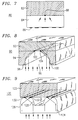
- FIG. 8 illustrates, in a three-dimensional view, an exemplary arrangement 90 wherein a first piece part 92 is to be joined to a second piece part 94.
- Second piece part 94 includes an aperture 96 with a pair of parabolic-shaped walls in opening 98 and 100, as shown. Therefore, an incoming collimated beam will be directed to the location of parabolic aperture 96, the focal lines being along 102 and 104 in this embodiment. Therefore, a pair of linear laser welds will be formed within a single aperture.
- FIG. 9 illustrates an embodiment 120 for providing linear laser welds.
- a first piece part 122 is to be laser welded to a second piece part 124, where piece part 124 is sufficiently transparent to the wavelength of the optical radiation used to perform the welding operation.
- Sidewalls 126 of piece part 124 are formed, as shown, to comprise parabolic shapes so as to focus the incoming collimated radiation along lines 130 and 132.
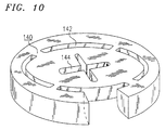
- FIG. 10 illustrates an exemplary piece part 140 including a plurality of various apertures which may be utilized as discussed above.
- the apertures of piece part 140 are shown as terminating in geometries other than a point or straight line.
- a set of four apertures 142 are illustrated as terminating in arcs, which may provide for bonding around the periphery of a circular piece part, for example.
- the apertures are formed to include sidewalls which provide for concentration of the laser radiation along the apex.
- Aperture 144 is illustrated as terminating in a cross-shaped apex, another suitable form. In general, any desired geometry may be used to provide the desired results.
- concentrating features may be utilized with various types of laser-based bonding procedures, including, but not limited to, welding, soldering or tacking
Landscapes
- Physics & Mathematics (AREA)
- Optics & Photonics (AREA)
- Engineering & Computer Science (AREA)
- Mechanical Engineering (AREA)
- Plasma & Fusion (AREA)
- Health & Medical Sciences (AREA)
- Electromagnetism (AREA)
- Toxicology (AREA)
- Lining Or Joining Of Plastics Or The Like (AREA)
- Laser Beam Processing (AREA)
- Adhesives Or Adhesive Processes (AREA)
Claims (4)
- Dispositif d'assemblage par laser comprenant une première pièce (par exemple 62, 72, 82) et une seconde pièce (par exemple 64, 74, 84) dans lequel la première pièce doit être assemblée par laser à la seconde pièce en au moins un site de fixation prédéterminé (par exemple 66, 78, 88), et au moins une pièce comprend une caractéristique structurale (par exemple 68, 76, 86) pour concentrer le rayonnement provenant du laser vers le ou les sites de fixation précités, cette caractéristique structurale comprenant un trajet transparent qui fait en sorte que le rayonnement concentré tombe sur le site de fixation, CARACTERISE EN CE QUE le trajet transparent de la caractéristique structurale comprend soit une surface mise en forme (par exemple 68) d'au moins une pièce transparente, à un emplacement capable d'assurer la concentration du rayonnement laser au site ou aux sites de fixation précités, soit une région (par exemple 76) à l'intérieur de la pièce transparente qui converge en biseau de façon à produire une réflexion interne suffisante pour concentrer le rayonnement laser vers le ou les sites de fixation précités, soit un réseau de diffraction (par exemple 86) formé sur la surface de la pièce ou des pièces transparentes.
- Dispositif suivant la revendication 1, dans lequel la caractéristique comprend une lentille.
- Dispositif suivant la revendication 1, dans lequel le réseau de diffraction comprend un réseau zoné.
- Dispositif suivant la revendication 1, dans lequel le ou les sites de fixation comprennent soit sensiblement un point ou un segment de ligne, ou comprennent un arc, ou comprennent une configuration géométrique prédéfini.
Priority Applications (1)
| Application Number | Priority Date | Filing Date | Title |
|---|---|---|---|
| EP97100835A EP0771607A3 (fr) | 1992-10-01 | 1993-09-22 | Un arrangement pour joindre au laser |
Applications Claiming Priority (2)
| Application Number | Priority Date | Filing Date | Title |
|---|---|---|---|
| US955168 | 1992-10-01 | ||
| US07/955,168 US5276303A (en) | 1992-10-01 | 1992-10-01 | Laser bonding scheme |
Related Child Applications (2)
| Application Number | Title | Priority Date | Filing Date |
|---|---|---|---|
| EP97100835A Division EP0771607A3 (fr) | 1992-10-01 | 1993-09-22 | Un arrangement pour joindre au laser |
| EP97100835.4 Division-Into | 1997-01-21 |
Publications (2)
| Publication Number | Publication Date |
|---|---|
| EP0590873A1 EP0590873A1 (fr) | 1994-04-06 |
| EP0590873B1 true EP0590873B1 (fr) | 1997-11-26 |
Family
ID=25496469
Family Applications (2)
| Application Number | Title | Priority Date | Filing Date |
|---|---|---|---|
| EP93307507A Expired - Lifetime EP0590873B1 (fr) | 1992-10-01 | 1993-09-22 | Dispositif pour joindre au laser |
| EP97100835A Withdrawn EP0771607A3 (fr) | 1992-10-01 | 1993-09-22 | Un arrangement pour joindre au laser |
Family Applications After (1)
| Application Number | Title | Priority Date | Filing Date |
|---|---|---|---|
| EP97100835A Withdrawn EP0771607A3 (fr) | 1992-10-01 | 1993-09-22 | Un arrangement pour joindre au laser |
Country Status (4)
| Country | Link |
|---|---|
| US (1) | US5276303A (fr) |
| EP (2) | EP0590873B1 (fr) |
| JP (1) | JPH06218567A (fr) |
| DE (1) | DE69315409T2 (fr) |
Families Citing this family (15)
| Publication number | Priority date | Publication date | Assignee | Title |
|---|---|---|---|---|
| JP3229146B2 (ja) * | 1994-12-28 | 2001-11-12 | キヤノン株式会社 | 液体噴射ヘッドおよびその製造方法 |
| EP1826800B1 (fr) * | 1996-12-12 | 2012-03-28 | Canon Kabushiki Kaisha | Changement d'espace en structure étanche |
| JP3847517B2 (ja) * | 2000-03-30 | 2006-11-22 | スタンレー電気株式会社 | 光エネルギーによる樹脂製部品溶着方法 |
| AU2002307442A1 (en) * | 2001-04-23 | 2002-11-05 | Dee E. Willden | Wedge-shaped lensless laser focusing device |
| JP4042439B2 (ja) * | 2002-03-18 | 2008-02-06 | トヨタ自動車株式会社 | レーザ溶着された組立体 |
| US6974207B2 (en) * | 2002-11-19 | 2005-12-13 | Lexmark International, Inc. | Laser welding methods and structures and control therefor including welded inkjet printheads |
| US20070056685A1 (en) * | 2003-09-18 | 2007-03-15 | Koninklijke Philips Electronics N.V. | Method to position a frame |
| US20050099449A1 (en) * | 2003-11-07 | 2005-05-12 | Tim Frasure | Methods and structures for disassembling inkjet printhead components and control therefor |
| JP4506203B2 (ja) * | 2004-02-27 | 2010-07-21 | 株式会社デンソー | 樹脂部材の継手構造、レーザ溶着方法及び電気機器の樹脂筐体 |
| WO2008068328A2 (fr) * | 2006-12-08 | 2008-06-12 | Mahle International Gmbh | Procédé de soudage au laser |
| FR2934187B1 (fr) * | 2008-07-24 | 2011-04-08 | Legris Sa | Procede de fabrication d'un dispositif par soudage laser, dispositif, element de ce dispositif et raccord pour la mise en oeuvre de ce procede |
| JP2012215528A (ja) * | 2011-04-01 | 2012-11-08 | Panasonic Industrial Devices Sunx Co Ltd | 検出センサ及び検出センサの製造方法 |
| ITUB20150956A1 (it) * | 2015-06-01 | 2016-12-01 | Automotive Lighting Italia S P A A Socio Unico | Metodo di realizzazione di un fanale automobilistico e relativo fanale automobilistico |
| US20190061272A1 (en) * | 2017-08-28 | 2019-02-28 | GM Global Technology Operations LLC | Method for laser welding of non-transmissive composite materials |
| DE102023001903B4 (de) | 2023-05-11 | 2025-02-06 | Mercedes-Benz Group AG | Verfahren zum Verbinden von mindestens zwei Bauteilen |
Family Cites Families (24)
| Publication number | Priority date | Publication date | Assignee | Title |
|---|---|---|---|---|
| US3304403A (en) * | 1963-10-14 | 1967-02-14 | Texas Instruments Inc | Laser welding of contacts |
| DE2343235B2 (de) * | 1973-08-28 | 1978-09-28 | Philips Patentverwaltung Gmbh, 2000 Hamburg | Verfahren zur Befestigung und Kontaktierung von elektrischen Subminiatur-Bauelementen auf gedruckten Schaltungen |
| US4237363A (en) * | 1977-02-04 | 1980-12-02 | Lemelson Jerome H | Beam welding apparatus and method |
| CH645208A5 (de) * | 1978-10-31 | 1984-09-14 | Bbc Brown Boveri & Cie | Verfahren zur herstellung von elektrischen kontakten an halbleiterbauelementen. |
| US4320281A (en) | 1980-07-31 | 1982-03-16 | Western Electric Company, Inc. | Laser bonding technique and article formed thereby |
| JPS57160590A (en) | 1981-03-31 | 1982-10-02 | Matsushita Electric Works Ltd | Welding method for contact point |
| JPS5897489A (ja) * | 1981-12-04 | 1983-06-09 | Hitachi Ltd | レ−ザ溶接方法 |
| JPS58119481A (ja) * | 1982-01-08 | 1983-07-15 | Kawasaki Steel Corp | レ−ザ溶接方法 |
| JPS6087987A (ja) * | 1983-10-19 | 1985-05-17 | Toshiba Corp | レ−ザ光によるかしめ方法 |
| NL8400939A (nl) * | 1984-03-23 | 1985-10-16 | Drukker D & Zn Nv | Werkwijze voor het bevestigen van een onderdeel uit diamant op metaal. |
| US4644126A (en) * | 1984-12-14 | 1987-02-17 | Ford Motor Company | Method for producing parallel-sided melt zone with high energy beam |
| JPS61169184A (ja) * | 1985-01-23 | 1986-07-30 | Toyota Motor Corp | 突合せ継手のレ−ザ溶接方法 |
| GB8620057D0 (en) * | 1986-08-18 | 1986-10-01 | Philips Nv | Cathode ray tube display device |
| US4737612A (en) * | 1987-02-04 | 1988-04-12 | Westinghouse Electric Corp. | Method of welding |
| US4883937A (en) * | 1987-09-30 | 1989-11-28 | Toyo Seikan Kaisha, Ltd. | Butt welding method by means of laser beam |
| US4833295A (en) * | 1988-05-17 | 1989-05-23 | Ford Motor Company | Welding of parts separated by a gap using a laser welding beam |
| DE3902292A1 (de) * | 1989-01-26 | 1990-08-02 | Bueco Buedenbender & Co | Verfahren und anordnung zum zusaetzlichen verschweissen eines falzes eines behaelters |
| US4992643A (en) * | 1989-08-25 | 1991-02-12 | United States Department Of Energy | Method and device for controlling plume during laser welding |
| DE3939866A1 (de) * | 1989-12-01 | 1991-06-06 | Baasel Carl Lasertech | Vorrichtung zum beschriften einer zylindermantelflaeche mittels lasergravur |
| US4959522A (en) * | 1990-01-12 | 1990-09-25 | Chrysler Corporation | Transparent pressure foot |
| US4990741A (en) * | 1990-02-06 | 1991-02-05 | Rockwell International Corporation | Method of laser welding |
| US5049720A (en) * | 1990-08-24 | 1991-09-17 | Fmc Corporation | Laser welding apparatus with sky window |
| DE4104256A1 (de) * | 1991-02-13 | 1992-08-20 | Thyssen Laser Technik Gmbh | Verfahren zum herstellen von durch tiefziehen umgeformten formkoerpern, insbesondere von karosserieteilen fuer kraftfahrzeuge |
| JP2799783B2 (ja) * | 1991-04-30 | 1998-09-21 | 東洋製罐株式会社 | 溶接缶胴の製造方法 |
-
1992
- 1992-10-01 US US07/955,168 patent/US5276303A/en not_active Expired - Lifetime
-
1993
- 1993-09-22 EP EP93307507A patent/EP0590873B1/fr not_active Expired - Lifetime
- 1993-09-22 EP EP97100835A patent/EP0771607A3/fr not_active Withdrawn
- 1993-09-22 DE DE69315409T patent/DE69315409T2/de not_active Expired - Fee Related
- 1993-10-01 JP JP5245829A patent/JPH06218567A/ja active Pending
Also Published As
| Publication number | Publication date |
|---|---|
| EP0771607A2 (fr) | 1997-05-07 |
| DE69315409D1 (de) | 1998-01-08 |
| JPH06218567A (ja) | 1994-08-09 |
| US5276303A (en) | 1994-01-04 |
| EP0590873A1 (fr) | 1994-04-06 |
| EP0771607A3 (fr) | 1997-06-04 |
| DE69315409T2 (de) | 1998-03-19 |
Similar Documents
| Publication | Publication Date | Title |
|---|---|---|
| EP0590873B1 (fr) | Dispositif pour joindre au laser | |
| CN102131614B (zh) | 带光纤激光器的激光焊接工具 | |
| JP2001334578A (ja) | レーザによる樹脂の溶着加工方法 | |
| US20240042546A1 (en) | Laser processing machine | |
| EP0267141B1 (fr) | Brasage de fils fins par double faisceau laser | |
| US4959522A (en) | Transparent pressure foot | |
| ES2100488T3 (es) | Procedimiento de soldadura borde con borde de por lo menos dos chapas. | |
| CN119781179A (zh) | 一种激光器光学模块、激光焊接头以及激光焊接方法 | |
| JP3866732B2 (ja) | 樹脂構造物のレーザー接合方法 | |
| KR100238162B1 (ko) | 마스크 프레임 제조방법 | |
| US4914272A (en) | Laser beam soldering apparatus and soldering method using the same | |
| JP2929447B2 (ja) | 溶接方法 | |
| US4960972A (en) | Light-beam-operated heating machine | |
| US20240173799A1 (en) | Methods for welding components of battery modules | |
| US7939779B2 (en) | Method for the laser machining of coated sheets | |
| EP0997222A1 (fr) | Dispositif pour l'usinage laser de materiaux | |
| JPS62263869A (ja) | ア−ク溶接方法 | |
| EP0997222A2 (fr) | Dispositif pour l'usinage laser de materiaux | |
| US5170029A (en) | Energy-beam welding method | |
| US20240165740A1 (en) | Methods for welding components of battery modules | |
| KR100198832B1 (ko) | 레이저 빔을 이용한 용접장치 | |
| JPH11156573A (ja) | レーザ加工ヘッド | |
| CN113084342A (zh) | 激光焊接的方法 | |
| JPS6240991A (ja) | レ−ザ溶接用集光レンズ | |
| JPH0123236B2 (fr) |
Legal Events
| Date | Code | Title | Description |
|---|---|---|---|
| PUAI | Public reference made under article 153(3) epc to a published international application that has entered the european phase |
Free format text: ORIGINAL CODE: 0009012 |
|
| AK | Designated contracting states |
Kind code of ref document: A1 Designated state(s): DE FR GB |
|
| RAP3 | Party data changed (applicant data changed or rights of an application transferred) |
Owner name: AT&T CORP. |
|
| 17P | Request for examination filed |
Effective date: 19940921 |
|
| 17Q | First examination report despatched |
Effective date: 19951109 |
|
| GRAG | Despatch of communication of intention to grant |
Free format text: ORIGINAL CODE: EPIDOS AGRA |
|
| GRAH | Despatch of communication of intention to grant a patent |
Free format text: ORIGINAL CODE: EPIDOS IGRA |
|
| GRAH | Despatch of communication of intention to grant a patent |
Free format text: ORIGINAL CODE: EPIDOS IGRA |
|
| GRAA | (expected) grant |
Free format text: ORIGINAL CODE: 0009210 |
|
| AK | Designated contracting states |
Kind code of ref document: B1 Designated state(s): DE FR GB |
|
| XX | Miscellaneous (additional remarks) |
Free format text: TEILANMELDUNG 97100835.4 EINGEREICHT AM 21/01/97. |
|
| REF | Corresponds to: |
Ref document number: 69315409 Country of ref document: DE Date of ref document: 19980108 |
|
| ET | Fr: translation filed | ||
| PLBE | No opposition filed within time limit |
Free format text: ORIGINAL CODE: 0009261 |
|
| STAA | Information on the status of an ep patent application or granted ep patent |
Free format text: STATUS: NO OPPOSITION FILED WITHIN TIME LIMIT |
|
| 26N | No opposition filed | ||
| PGFP | Annual fee paid to national office [announced via postgrant information from national office to epo] |
Ref country code: FR Payment date: 20010823 Year of fee payment: 9 |
|
| PGFP | Annual fee paid to national office [announced via postgrant information from national office to epo] |
Ref country code: GB Payment date: 20010828 Year of fee payment: 9 |
|
| PGFP | Annual fee paid to national office [announced via postgrant information from national office to epo] |
Ref country code: DE Payment date: 20010928 Year of fee payment: 9 |
|
| REG | Reference to a national code |
Ref country code: GB Ref legal event code: IF02 |
|
| PG25 | Lapsed in a contracting state [announced via postgrant information from national office to epo] |
Ref country code: GB Free format text: LAPSE BECAUSE OF NON-PAYMENT OF DUE FEES Effective date: 20020922 |
|
| PG25 | Lapsed in a contracting state [announced via postgrant information from national office to epo] |
Ref country code: DE Free format text: LAPSE BECAUSE OF NON-PAYMENT OF DUE FEES Effective date: 20030401 |
|
| GBPC | Gb: european patent ceased through non-payment of renewal fee |
Effective date: 20020922 |
|
| PG25 | Lapsed in a contracting state [announced via postgrant information from national office to epo] |
Ref country code: FR Free format text: LAPSE BECAUSE OF NON-PAYMENT OF DUE FEES Effective date: 20030603 |
|
| REG | Reference to a national code |
Ref country code: FR Ref legal event code: ST |