EP0591245B1 - Verlängerter hohlkörper - Google Patents
Verlängerter hohlkörper Download PDFInfo
- Publication number
- EP0591245B1 EP0591245B1 EP92910786A EP92910786A EP0591245B1 EP 0591245 B1 EP0591245 B1 EP 0591245B1 EP 92910786 A EP92910786 A EP 92910786A EP 92910786 A EP92910786 A EP 92910786A EP 0591245 B1 EP0591245 B1 EP 0591245B1
- Authority
- EP
- European Patent Office
- Prior art keywords
- hollow member
- hand
- functional
- pipe
- hollow
- Prior art date
- Legal status (The legal status is an assumption and is not a legal conclusion. Google has not performed a legal analysis and makes no representation as to the accuracy of the status listed.)
- Expired - Lifetime
Links
Images
Classifications
-
- B—PERFORMING OPERATIONS; TRANSPORTING
- B65—CONVEYING; PACKING; STORING; HANDLING THIN OR FILAMENTARY MATERIAL
- B65G—TRANSPORT OR STORAGE DEVICES, e.g. CONVEYORS FOR LOADING OR TIPPING, SHOP CONVEYOR SYSTEMS OR PNEUMATIC TUBE CONVEYORS
- B65G7/00—Devices for assisting manual moving or tilting heavy loads
- B65G7/12—Load carriers, e.g. hooks, slings, harness, gloves, modified for load carrying
-
- B—PERFORMING OPERATIONS; TRANSPORTING
- B25—HAND TOOLS; PORTABLE POWER-DRIVEN TOOLS; MANIPULATORS
- B25B—TOOLS OR BENCH DEVICES NOT OTHERWISE PROVIDED FOR, FOR FASTENING, CONNECTING, DISENGAGING, OR HOLDING
- B25B9/00—Hand-held gripping tools other than those covered by group B25B7/00
-
- F—MECHANICAL ENGINEERING; LIGHTING; HEATING; WEAPONS; BLASTING
- F16—ENGINEERING ELEMENTS AND UNITS; GENERAL MEASURES FOR PRODUCING AND MAINTAINING EFFECTIVE FUNCTIONING OF MACHINES OR INSTALLATIONS; THERMAL INSULATION IN GENERAL
- F16L—PIPES; JOINTS OR FITTINGS FOR PIPES; SUPPORTS FOR PIPES, CABLES OR PROTECTIVE TUBING; MEANS FOR THERMAL INSULATION IN GENERAL
- F16L1/00—Laying or reclaiming pipes; Repairing or joining pipes on or under water
- F16L1/024—Laying or reclaiming pipes on land, e.g. above the ground
- F16L1/06—Accessories therefor, e.g. anchors
Definitions
- This invention relates to elongate hollow members, and more particularly to elongate hollow members in the form of pipes and conduits, especially plastic pipe fittings.
- Plastics pipes are now widely used in place of the more traditional earthenware and metal pipes for carrying fluids, for example, in the water, water treatment, and gas industries.
- Various fittings are used to join lengths of plastic pipe, of which thermoplastic heat-fusion pipe fittings are extremely popular.
- the designs for such fittings fall into three basic types. Firstly, those having an electric heating element which is embedded in the body of the fitting and located in close proximity to the surface of the fitting that is to be joined to the pipe by heat fusion.
- the fitting may have a metal core embedded in the body thereof, in which eddy currents can be induced by the action of an induction coil thereby producing a heating effect in the core.
- the present invention provides an elongate hollow member comprising a thermoplastic heat fusion pipe fitting and having at least one open end, and having on its external surface either
- the functional member is dedicated to its purpose, that is to say it should not be associated with secondary functions such as, for example, making electrical connections, connections to another member, or passing a fluid into or out of said hollow member.
- the functional member may be subjected to quite severe mechanical stresses in use, and such secondary functions may well be hindered or damaged if associated therewith.
- the functional member is not associated with electrical connections, is not adapted to be connected to another member, is not adapted to pass a fluid into or out of said pipe, and is preferably not a strengthening member.
- thermoplastic pipe fittings such as plastics sleeves and connecting pieces, for example, those made from thermoplastic materials such as polyolefins, for example, polyethylene or polypropylene.
- suitable thermoplastic materials are vinyl resins for example, polyvinylchloride; polystyrene; or acrylic resins.
- the thermoplastic material can be a crosslinked thermoplastic material, for example, cross linked polyethylene.
- the invention is primarily applicable to relatively short hollow members, for example sleeves or other fittings adapted for sliding over or into other pipes, or fittings such as connecting pieces.
- the invention is applicable to any length of hollow member suitable for the intended use and the longer the hollow member, the greater the number of functional members which is desirable.
- the length of the hollow member may range from a few cms, say for example about 5 cms, to several metres, for example up to 3 metres.
- the length of the hollow member is from about 10 cms to about 60 cms.
- the invention finds particular application when the maximum diameter of the pipe to be joined is about 180 mms or greater, especially 250 mms or greater and particularly up to and including 315 mms or more, for example up to and including 400 mms.
- the functional member may be secured to the hollow member, for example, by welding or fusion or may be integrally moulded to the hollow member.
- the integral moulding is especially suitable when the hollow member is relatively short.
- the functional member can be a separate item, having means for attachment to a boss or other mounting means moulded into the external surface of the hollow member.
- the functional member can take the form of a handle which is so shaped that it can be gripped or held by the hand so as to be able to lift or move the hollow member.
- a handle primarily designed for lifting the hollow member from one place to another is a T-shape member integrally moulded with or attached to the hollow member, for example, by means of a screw-threaded boss or similar mounting means so that the top of the T is spaced from the hollow member.
- the top of the T can run substantially parallel to the axis of the hollow member, or at an angle thereto.
- the "vertical" portion of the T will have to be long enough for the fingers of the hand to be able to be inserted between the "horizontal" portion of the T and the pipe.
- Another suitable form of handle would be a loop in which the fingers could be inserted, or a ball, disc or other suitable means to gain purchase.
- handle which are primarily intended to facilitate the manoeuvring of the hollow member as opposed to facilitating the lifting of the hollow member are simple rods extending outwards from the surface of the hollow member, ie, extending radially outwards if the hollow member is of circular cross-section. These rods may have indentations for the fingers, and may be slightly tapered if desired but these features are not essential.
- For lifting the hollow member it will usually be necessary to provide two directly opposed rods, and if the pipe is circular, they can be diametrically opposed.
- one suitably shaped rod may be used in some cases, particularly where its function is mainly to facilitate rotation of the hollow member.
- the elongate hollow member may comprise a pipe of circular section having a T-shaped handle and/or two diametrically opposed rods, which may be tapered handles.
- the hollow member is provided with a least one surface feature or indentation adapted to provide hand gripping means.
- the surface feature may be proud of the surface of the hollow member, for example, it may comprise corrugations, or a knurled region extending around the hollow member circumference.
- the hand gripping means may comprise indentations having recessed or under-cut portions into which the fingers can be inserted so as to grip the hollow member. In the latter embodiment the gripping means may be flush with the surface, which can provide an advantage in certain circumstances.
- the functional member is not associated with electrical connections, not adapted to be connected to another member, not adapted to pass a fluid into out of the pipe, and preferably not a strengthening member.
- the functional member should not have an electrical cable inserted therein and is not a sleeve or chimney surrounding an electrical connection.
- it should not be adapted to be connected to other pipes or electrical cables, e.g. a flange, and it should not be a branch pipe whereby fluid would be able to leave or enter the hollow member of the invention.
- the functional member is preferably not a strengthening member such as, for example, a tension-sustaining reinforcing member.
- the elongate hollow member of the invention comprises a heat-fusion pipe fitting which can be used, for example, for joining lengths of thermoplastic or cross-linked plastic pipe.
- the elongate hollow member comprises a pipe fitting which has a body portion adapted to accommodate plastic pipes at both ends.
- the pipe fitting has an electrical heating element which is embedded therein and which is connected to terminals outside the body portion, to which terminals electric power is supplied on installation. When the heating element is powered, the pipe fitting softens in the locality of the heating element and fuses the fitting to the pipes located in the ends of the body portion. Some fusion of the pipe surface may also occur when thermoplastic pipes such as, for example, polyethylene pipes are used, thus strengthening the bond.
- the pipe fitting may be provided with an adhesive on its internal surface, which is activated by heat from the heating element to melt and form a bond.
- both the pipes to be joined and the hollow member of the invention are made from the same thermoplastic material, most preferably a polyethylene.
- the invention provides a great advance in easing the carrying or transporting of pipe fitting such as sleeves, and connecting pieces around a site, but there are also further advantages. It has been found that operators can handle a pipe fitting without gripping the internal (fused area) surface of the fitting, thereby eliminating a potential source of contamination. Particularly for polyethylene pipes, the surfaces of which are glossy and slippery, it has been found that the presence of one or more functional members improves the ability of the operator to locate the fitting in the correct position by rotating, swivelling and/or sliding the fitting or coupling into place. Additionally it has been found that when the pipes are buried underground, the functional members which protrude from the pipe, provide additional anchorage against pipe displacement due to expansion and contraction of the system. They thus act as soil stress anchors along the pipeline.
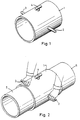
- pipe fitting 1 is provided with two diametrically located, tapered handles 2 and 3. Also provided is a T-shaped handle 4, disposed on a radius transverse to the axis of the tapered handles.
Landscapes
- Engineering & Computer Science (AREA)
- Mechanical Engineering (AREA)
- General Engineering & Computer Science (AREA)
- Lining Or Joining Of Plastics Or The Like (AREA)
Claims (9)
- Länglicher Hohlkörper mit einem thermoplastischen, wärmeschmelzbaren Rohrverbindungsstück (1) und mit wenigstens einem offenen Ende, dadurch gekennzeichnet, daß er auf seiner Außenoberfläche entweder(i) Spezialeinrichtungen (2, 3, 4) zum Heben, Bewegen oder Drehen des Hohlkörpers von Hand aufweist, wobei die Hebe-, Bewegungs- oder Dreheinrichtungen (2, 3, 4)(a) wenigstens ein Funktionselement (2, 3, 4), das an dem Hohlkörper befestigt oder einstückig mit ihm gegossen ist, sich von ihm nach auswärts erstreckt und so geformt ist, daß es von Hand gegriffen oder gehalten werden kann, oder(b) wenigstens ein Oberflächenmerkmal oder eine Vertiefung zur Ausbildung einer Handgriffeinrichtungenthalten, oder(ii) an seiner Außenoberfläche wenigstens eine Befestigungs- oder Montageeinrichtung aufweist, die zum Zusammenwirken und Eingriff mit einem Funktionselement ausgelegt ist, um dieses an dem Hohlkörper zu befestigen oder anzubringen, wobei das Funktionselement so geformt ist, daß es von Hand gegriffen oder gehalten werden kann,und wobei die Anordnung derart vorgesehen ist, daß der Hohlkörper unter Verwendung des Funktionselements oder der Handgriffeinrichtungen von Hand gehoben, bewegt oder gedreht werden kann, ohne daß die Innenoberfläche des Hohlkörpers berührt und ohne daß mit den Händen unter dem Hohlkörper hindurchgegriffen wird.
- Hohlkörper nach Anspruch 1, dadurch gekennzeichnet, daß das Funktionselement (2, 3, 4) nicht mit elektrischen Anschlüssen in Zusammenhang steht, nicht zum Anschluß an ein anderes Element ausgelegt und nicht zum Durchlassen eines Fluids in das Rohr hinein oder aus diesem heraus vorgesehen ist.
- Hohlkörper nach Anspruch 2, bei dem das Funktionselement (2, 3, 4) kein Verstärkungselement ist.
- Hohlkörper nach Anspruch 2 oder 3, dadurch gekennzeichnet, daß er eine Hülse (1) oder ein Anschlußstück (1) ist.
- Hohlkörper nach einem der vorhergehenden Ansprüche, dadurch gekennzeichnet, daß er aus Polyethylen besteht.
- Hohlkörper nach einem der vorhergehenden Ansprüche, dadurch gekennzeichnet, daß er eine Länge von 10 cm bis 60 cm und einen Durchmesser von 180 mm bis 400 mm aufweist.
- Hohlkörper nach einem der vorhergehenden Ansprüche, dadurch gekennzeichnet, daß er einen kreisförmigen Querschnitt und einen T-förmigen Griff (4) und/oder zwei einander diametral entgegengesetzte, sich verjüngende Griffe (2, 3) aufweist.
- Hohlkörper nach einem der vorhergehenden Ansprüche, dadurch gekennzeichnet, daß er ein Rohrverbindungsstück (1) enthält, das einen Körperbereich zum Aufnehmen von Plastikrohren (5, 6) an seinen beiden Enden aufweist und mit einem darin eingebetteten elektrischen Heizelement versehen ist, das mit Anschlüssen außerhalb des Körperbereichs verbunden ist.
- Manuelle Handhabung eines länglichen Hohlkörpers, gekennzeichnet durch einen Hohlkörper (1), wie er in einem der Ansprüche 1 bis 8 beansprucht ist.
Applications Claiming Priority (5)
| Application Number | Priority Date | Filing Date | Title |
|---|---|---|---|
| GB9111777 | 1991-05-31 | ||
| GB9111777A GB2256252A (en) | 1991-05-31 | 1991-05-31 | Manhandling pipes |
| GB9126624A GB2256691B (en) | 1991-05-31 | 1991-12-16 | Elongate hollow member |
| GB9126624 | 1991-12-16 | ||
| PCT/GB1992/000965 WO1992021907A1 (en) | 1991-05-31 | 1992-05-28 | Elongate hollow member |
Publications (2)
| Publication Number | Publication Date |
|---|---|
| EP0591245A1 EP0591245A1 (de) | 1994-04-13 |
| EP0591245B1 true EP0591245B1 (de) | 1995-08-02 |
Family
ID=26298985
Family Applications (1)
| Application Number | Title | Priority Date | Filing Date |
|---|---|---|---|
| EP92910786A Expired - Lifetime EP0591245B1 (de) | 1991-05-31 | 1992-05-28 | Verlängerter hohlkörper |
Country Status (7)
| Country | Link |
|---|---|
| EP (1) | EP0591245B1 (de) |
| AU (1) | AU1769392A (de) |
| DE (1) | DE69203864T2 (de) |
| DK (1) | DK0591245T3 (de) |
| HU (1) | HU212737B (de) |
| PL (1) | PL169806B1 (de) |
| WO (1) | WO1992021907A1 (de) |
Families Citing this family (2)
| Publication number | Priority date | Publication date | Assignee | Title |
|---|---|---|---|---|
| EP0608673A1 (de) * | 1993-01-25 | 1994-08-03 | Santens Engineering Services Nv | Verfahren und Vorrichtung zum Greifen und Fördern von Flaschen |
| DE102008046677A1 (de) * | 2008-09-10 | 2010-03-11 | Josef Zimmermann | Rohrstück mit mindestens einer innen liegenden, umlaufenden Dichtung |
Family Cites Families (4)
| Publication number | Priority date | Publication date | Assignee | Title |
|---|---|---|---|---|
| US2749173A (en) * | 1952-06-06 | 1956-06-05 | United States Steel Corp | Gripping apparatus for handling elongated objects |
| US4697830A (en) * | 1984-12-31 | 1987-10-06 | Petro-Tube, Inc. | Stabbing guide |
| US4723800A (en) * | 1987-06-03 | 1988-02-09 | The United States Of America As Represented By The Administrator, National Aeronautics And Space Administration | Bi-stem gripping apparatus |
| US4915422A (en) * | 1989-01-06 | 1990-04-10 | The American Brass & Iron Foundry | Pipe coupling |
-
1992
- 1992-05-28 EP EP92910786A patent/EP0591245B1/de not_active Expired - Lifetime
- 1992-05-28 AU AU17693/92A patent/AU1769392A/en not_active Abandoned
- 1992-05-28 PL PL92301423A patent/PL169806B1/pl not_active IP Right Cessation
- 1992-05-28 HU HU9303384A patent/HU212737B/hu not_active IP Right Cessation
- 1992-05-28 DK DK92910786T patent/DK0591245T3/da active
- 1992-05-28 DE DE69203864T patent/DE69203864T2/de not_active Expired - Fee Related
- 1992-05-28 WO PCT/GB1992/000965 patent/WO1992021907A1/en not_active Ceased
Also Published As
| Publication number | Publication date |
|---|---|
| HUT65952A (en) | 1994-08-29 |
| WO1992021907A1 (en) | 1992-12-10 |
| DK0591245T3 (da) | 1995-12-04 |
| EP0591245A1 (de) | 1994-04-13 |
| PL169806B1 (en) | 1996-09-30 |
| DE69203864D1 (de) | 1995-09-07 |
| DE69203864T2 (de) | 1996-04-18 |
| HU212737B (en) | 1996-10-28 |
| HU9303384D0 (en) | 1994-03-28 |
| AU1769392A (en) | 1993-01-08 |
Similar Documents
| Publication | Publication Date | Title |
|---|---|---|
| EP0939874B1 (de) | Rohrverbindung | |
| WO1992016987A1 (en) | Heat reshapeable rigid conduit | |
| NZ212786A (en) | Joining plastics pipes: tapered pipe ends welded into mating sleeve | |
| TR199801421T2 (xx) | Bir boru ile ba�lant� donan�m�n� f�zyonla birle�tirme cihaz� ve y�ntemi. | |
| EP0591245B1 (de) | Verlängerter hohlkörper | |
| WO2002077507A3 (en) | Method of laying pipe-in-pipe structures and device for use therein | |
| GB2256691A (en) | Manhandling pipes | |
| GB2141201A (en) | Pipe-cleaning pull through | |
| AU1287792A (en) | Weldable pipe fittings and pipe joints formed therewith | |
| EP3225896A1 (de) | Elektroschweissbarer sattelförmiger rohrverbinder und entsprechendes schweissverfahren | |
| US5988199A (en) | Corporation stop assembly | |
| US6224116B1 (en) | Device for holding pipe on a branch connector | |
| CA1039329A (en) | Telescoping pipe fitting | |
| JP5508931B2 (ja) | 管口閉塞キャップを備えた管部材 | |
| JP2000291838A (ja) | 埋設管の更生用テーパ管 | |
| JP4625166B2 (ja) | 管連結構造 | |
| KR100496431B1 (ko) | 피복형 파형강관의 이음구조 | |
| KR100328782B1 (ko) | 자중을 이용하여 쉽게 접합하는 대형 상, 하수 관 및 그접합방법 | |
| JPH0619912Y2 (ja) | 溶着継手 | |
| CN217169825U (zh) | 用于hdpe管弯头的电熔对接辅助工具 | |
| EP0045764A1 (de) | Verfahren zur verbindung von rohren. | |
| WO1994024478A1 (en) | Article and method for modifying the surface of a substrate | |
| JPH10185067A (ja) | エレクトロフュージョン継手 | |
| JPH0629591Y2 (ja) | 樹脂管の分岐部 | |
| SU1122519A1 (ru) | Тройник дл соединени труб из термопластов |
Legal Events
| Date | Code | Title | Description |
|---|---|---|---|
| PUAI | Public reference made under article 153(3) epc to a published international application that has entered the european phase |
Free format text: ORIGINAL CODE: 0009012 |
|
| 17P | Request for examination filed |
Effective date: 19931026 |
|
| AK | Designated contracting states |
Kind code of ref document: A1 Designated state(s): DE DK FR GB |
|
| 17Q | First examination report despatched |
Effective date: 19940616 |
|
| GRAA | (expected) grant |
Free format text: ORIGINAL CODE: 0009210 |
|
| RAP1 | Party data changed (applicant data changed or rights of an application transferred) |
Owner name: UPONOR LIMITED |
|
| AK | Designated contracting states |
Kind code of ref document: B1 Designated state(s): DE DK FR GB |
|
| REF | Corresponds to: |
Ref document number: 69203864 Country of ref document: DE Date of ref document: 19950907 |
|
| ET | Fr: translation filed | ||
| REG | Reference to a national code |
Ref country code: DK Ref legal event code: T3 |
|
| PLBE | No opposition filed within time limit |
Free format text: ORIGINAL CODE: 0009261 |
|
| STAA | Information on the status of an ep patent application or granted ep patent |
Free format text: STATUS: NO OPPOSITION FILED WITHIN TIME LIMIT |
|
| 26N | No opposition filed | ||
| REG | Reference to a national code |
Ref country code: GB Ref legal event code: IF02 |
|
| PGFP | Annual fee paid to national office [announced via postgrant information from national office to epo] |
Ref country code: DK Payment date: 20080415 Year of fee payment: 17 Ref country code: DE Payment date: 20080425 Year of fee payment: 17 |
|
| PGFP | Annual fee paid to national office [announced via postgrant information from national office to epo] |
Ref country code: FR Payment date: 20080414 Year of fee payment: 17 |
|
| PGFP | Annual fee paid to national office [announced via postgrant information from national office to epo] |
Ref country code: GB Payment date: 20080425 Year of fee payment: 17 |
|
| REG | Reference to a national code |
Ref country code: FR Ref legal event code: CD |
|
| REG | Reference to a national code |
Ref country code: DK Ref legal event code: EBP |
|
| GBPC | Gb: european patent ceased through non-payment of renewal fee |
Effective date: 20090528 |
|
| REG | Reference to a national code |
Ref country code: FR Ref legal event code: ST Effective date: 20100129 |
|
| PG25 | Lapsed in a contracting state [announced via postgrant information from national office to epo] |
Ref country code: FR Free format text: LAPSE BECAUSE OF NON-PAYMENT OF DUE FEES Effective date: 20090602 Ref country code: DK Free format text: LAPSE BECAUSE OF NON-PAYMENT OF DUE FEES Effective date: 20090531 |
|
| PG25 | Lapsed in a contracting state [announced via postgrant information from national office to epo] |
Ref country code: GB Free format text: LAPSE BECAUSE OF NON-PAYMENT OF DUE FEES Effective date: 20090528 |
|
| PG25 | Lapsed in a contracting state [announced via postgrant information from national office to epo] |
Ref country code: DE Free format text: LAPSE BECAUSE OF NON-PAYMENT OF DUE FEES Effective date: 20091201 |