EP0591602A1 - Appareil de conditionnement d'air pour zones d'espaces intérieures - Google Patents
Appareil de conditionnement d'air pour zones d'espaces intérieures Download PDFInfo
- Publication number
- EP0591602A1 EP0591602A1 EP92890213A EP92890213A EP0591602A1 EP 0591602 A1 EP0591602 A1 EP 0591602A1 EP 92890213 A EP92890213 A EP 92890213A EP 92890213 A EP92890213 A EP 92890213A EP 0591602 A1 EP0591602 A1 EP 0591602A1
- Authority
- EP
- European Patent Office
- Prior art keywords
- air
- profile
- cover
- posts
- facing
- Prior art date
- Legal status (The legal status is an assumption and is not a legal conclusion. Google has not performed a legal analysis and makes no representation as to the accuracy of the status listed.)
- Withdrawn
Links
Images


Classifications
-
- E—FIXED CONSTRUCTIONS
- E06—DOORS, WINDOWS, SHUTTERS, OR ROLLER BLINDS IN GENERAL; LADDERS
- E06B—FIXED OR MOVABLE CLOSURES FOR OPENINGS IN BUILDINGS, VEHICLES, FENCES OR LIKE ENCLOSURES IN GENERAL, e.g. DOORS, WINDOWS, BLINDS, GATES
- E06B7/00—Special arrangements or measures in connection with doors or windows
- E06B7/02—Special arrangements or measures in connection with doors or windows for providing ventilation, e.g. through double windows; Arrangement of ventilation roses
- E06B7/10—Special arrangements or measures in connection with doors or windows for providing ventilation, e.g. through double windows; Arrangement of ventilation roses by special construction of the frame members
-
- E—FIXED CONSTRUCTIONS
- E04—BUILDING
- E04B—GENERAL BUILDING CONSTRUCTIONS; WALLS, e.g. PARTITIONS; ROOFS; FLOORS; CEILINGS; INSULATION OR OTHER PROTECTION OF BUILDINGS
- E04B2/00—Walls, e.g. partitions, for buildings; Wall construction with regard to insulation; Connections specially adapted to walls
- E04B2/88—Curtain walls
- E04B2/96—Curtain walls comprising panels attached to the structure through mullions or transoms
-
- F—MECHANICAL ENGINEERING; LIGHTING; HEATING; WEAPONS; BLASTING
- F24—HEATING; RANGES; VENTILATING
- F24F—AIR-CONDITIONING; AIR-HUMIDIFICATION; VENTILATION; USE OF AIR CURRENTS FOR SCREENING
- F24F5/00—Air-conditioning systems or apparatus not covered by F24F1/00 or F24F3/00, e.g. using solar heat or combined with household units such as an oven or water heater
- F24F5/0075—Systems using thermal walls, e.g. double window
-
- F—MECHANICAL ENGINEERING; LIGHTING; HEATING; WEAPONS; BLASTING
- F24—HEATING; RANGES; VENTILATING
- F24F—AIR-CONDITIONING; AIR-HUMIDIFICATION; VENTILATION; USE OF AIR CURRENTS FOR SCREENING
- F24F7/00—Ventilation
- F24F7/04—Ventilation with ducting systems, e.g. by double walls; with natural circulation
- F24F7/06—Ventilation with ducting systems, e.g. by double walls; with natural circulation with forced air circulation, e.g. by fan positioning of a ventilator in or against a conduit
- F24F7/08—Ventilation with ducting systems, e.g. by double walls; with natural circulation with forced air circulation, e.g. by fan positioning of a ventilator in or against a conduit with separate ducts for supplied and exhausted air with provisions for reversal of the input and output systems
-
- F—MECHANICAL ENGINEERING; LIGHTING; HEATING; WEAPONS; BLASTING
- F24—HEATING; RANGES; VENTILATING
- F24F—AIR-CONDITIONING; AIR-HUMIDIFICATION; VENTILATION; USE OF AIR CURRENTS FOR SCREENING
- F24F5/00—Air-conditioning systems or apparatus not covered by F24F1/00 or F24F3/00, e.g. using solar heat or combined with household units such as an oven or water heater
- F24F5/0075—Systems using thermal walls, e.g. double window
- F24F2005/0082—Facades
-
- Y—GENERAL TAGGING OF NEW TECHNOLOGICAL DEVELOPMENTS; GENERAL TAGGING OF CROSS-SECTIONAL TECHNOLOGIES SPANNING OVER SEVERAL SECTIONS OF THE IPC; TECHNICAL SUBJECTS COVERED BY FORMER USPC CROSS-REFERENCE ART COLLECTIONS [XRACs] AND DIGESTS
- Y02—TECHNOLOGIES OR APPLICATIONS FOR MITIGATION OR ADAPTATION AGAINST CLIMATE CHANGE
- Y02A—TECHNOLOGIES FOR ADAPTATION TO CLIMATE CHANGE
- Y02A30/00—Adapting or protecting infrastructure or their operation
-
- Y—GENERAL TAGGING OF NEW TECHNOLOGICAL DEVELOPMENTS; GENERAL TAGGING OF CROSS-SECTIONAL TECHNOLOGIES SPANNING OVER SEVERAL SECTIONS OF THE IPC; TECHNICAL SUBJECTS COVERED BY FORMER USPC CROSS-REFERENCE ART COLLECTIONS [XRACs] AND DIGESTS
- Y02—TECHNOLOGIES OR APPLICATIONS FOR MITIGATION OR ADAPTATION AGAINST CLIMATE CHANGE
- Y02B—CLIMATE CHANGE MITIGATION TECHNOLOGIES RELATED TO BUILDINGS, e.g. HOUSING, HOUSE APPLIANCES OR RELATED END-USER APPLICATIONS
- Y02B30/00—Energy efficient heating, ventilation or air conditioning [HVAC]
- Y02B30/90—Passive houses; Double facade technology
Definitions
- the present invention relates to a device for conditioning interior zones and the like gaps according to the preamble of patent claim 1.
- So-called building envelope systems which are independent of shape and material, are known, in which one of the functional layer levels, that is to say the room end wall in relation to the curtain-facing weather protection layer level, is provided.
- This weather protection layer generally consists of a number of glass panes arranged next to and / or one above the other, corresponding to the size of the room end wall, the essentially closed front of which serves as rain protection or as a shading wall.
- the glass panes arranged one above the other are each fixed with open joints at a distance of 6 to 8 mm from one another.
- this construction is no longer applicable if, for example, there are high demands on sound insulation and / or if, for example, the weather protection layer is arranged at an incline or is to be realized in connection with sloping roofs; In these cases, water penetrates when it rains and reaches the zones of the end wall, which may result Leads to interference.
- the air exchange between the rear ventilation space and the weather side (outside) of the weather protection layer level takes place completely unregulated or via complex control flaps, so that the temperature in the rear ventilation space either automatically follows the outside temperature or that complicated and visually disturbing flaps or the like are required.
- the object underlying the present invention is therefore to provide a device of the generic type with which a defined conditioning, i.e. Ventilation, for example, of ventilation spaces and similar interior zones is possible and with which an inclined and possibly soundproofed weather protection layer can be verified without fear of water and noise or sound penetrating.
- a defined conditioning i.e. Ventilation, for example, of ventilation spaces and similar interior zones is possible and with which an inclined and possibly soundproofed weather protection layer can be verified without fear of water and noise or sound penetrating.
- the subclaims relate to particular refinements, developments and improvements with regard to the design of the profile posts, in particular also with regard to additional measures and additional means.
- measures are also disclosed which have the goal of targeted water supply or drainage in or on the facade with subsequent collection of the water.
- FIG. 1 shows a basic illustration of a building envelope system 1, to which a plurality of room or floor ceilings 2 are arranged one above the other. These room or floor ceilings 2 form with the room end wall 3, which is optionally formed by a so-called fixed glazing system or by openable window systems, a closed building system.
- the room end wall 3 can now be at a constant distance from a so-called weather protection layer 4, which is anchored in the area of the room or floor ceilings 2 and thus forms a second front of the building.
- This weather protection layer level 4 consists of a multiplicity of individual plates arranged next to and / or one above the other, especially glass panes.
- a rear ventilation space 5 into which, for example, window air flows in from the inside and into the air vents from the outside of the building or air inlets or the like can flow in and out, which can optionally be additionally heated or cooled.
- a certain temperature is set depending on the outside and inside of the building.
- said air exchange takes place in an uncontrolled manner without sound insulation from or to the rear ventilation space 5 via spacing slots, ie the joints between the glass panes of the weather layer level 4 arranged one above the other.
- said air exchange takes place in a regulated and sound-insulated manner, namely over correspondingly constructively designed profile posts for guiding and holding the glass panes of the weather protection layer level 4.
- FIGS. 2 and 3 show - in the plane of a room or floor-ceiling 2 according to FIG. 1 - one fastening anchor 7 each, via which, for example, a fixed glazing system 8 known per se is anchored to the building wall; the fixed glazing systems 8 form the room end wall 3 mentioned in connection with FIG. 1 and, as shown in FIG. 2 and FIG. 3, generally have a so-called double glazing 9 on.
- These double glazings 9 are inserted tightly in holding profiles or profile frames 10 and thus form the building physics, functional layer level of the building envelope system 1 according to FIG. 1 can be fixed to the fastening anchors and insulating glass panes can also be provided instead of single glazing.
- the profile posts 100 can be fixed to the building wall either via rigid, rigid bulkheads 11 (FIG. 2) or hollow cylindrical bulkheads 12 (FIG. 3).
- the width or depth of these bulkheads 11 and 12 determines the depth and thus the volume of the rear ventilation spaces 5 and it should be pointed out here that the bulkheads 11 and 12 can be integrated into the ventilation system to be described with reference to the other figures .
- the rigid bulkheads 11 serve for the vertical separation of, for example, rear ventilation spaces 5 and can thus be specifically integrated into an air circulation; and also the hollow cylindrical partitions 12, which, unlike shown in FIG.
- the bulkheads 11, 12 can be used specifically for the forced guidance of the air flowing in the ventilation spaces 5.
- the above-mentioned bulkheads 11 and 12 are connected to the fastening anchors 7 on the building side and are guided and held on their free longitudinal sides in guide slots (compare 122 in FIGS. 4 ... 8) of the profile posts 100.
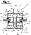
- the profile posts 100 are shown in FIGS. 4 ... 14 - in eleven different exemplary embodiments.
- the basic principle or functional principle of the profile post 100 will first be explained in detail with reference to FIG. 4.
- the basic element is referred to as a double U, the individual U 101/102 of which are connected to one another on the foot side, in such a way that, when viewed over the length of the profile posts 100, a plurality of openings, in particular elongated holes, are provided, which ultimately serve as the first air passage openings 103 act.
- glass panes 104 are inserted and fixed on both sides to the open legs of the U's 101/102 via glazing strips 105.
- the glass panes 104 can be implemented as single panes, but also as insulating glass panes.
- the air passage openings 103 are preferably covered with, for example, fly screens and, in a special embodiment of the air passage openings 103, it is provided to assign these slide elements, via which the total cross section for the air passage can be varied.
- a cover 106 is placed in front of the outside of the double U 101/102.
- This facing 106 overlaps the double U 101/102 with first webs 107, which determine a defined air gap 108 of 5 or 6 mm, for example, towards the glass panes 104.
- the connection between the facing 106 and the double U 101/102 is realized as a clip connection 109, with flanks 110 projecting inwards on the first webs 107 latching onto complementary rails 111 arranged parallel to the outside of the double U 101/102.
- second air passage openings 112 are provided, through which air entering through the air slot 108 can flow to the first air passage openings 103 and from here to the rear ventilation spaces 5.
- the flow cross-sections of the air (see arrow Y) from the air slot 108 to the second air passage openings 112 and from here to the first air passage openings 103, which are laterally offset for sound insulation reasons, are dimensioned in accordance with one another in accordance with flow principles.
- the fly screen protection 112 ′ is provided at the second air passage openings 112 and it should also be noted are so-called tear-off edges 113 are provided on the deflection edges of the air flow from, for example, the second air passage openings 112 to the first air passage openings 103, in order, for example, to remove moisture entrained in the air flowing from the outside to the rear ventilation spaces 5.
- a web 130 dividing the air flow is provided in the center, which prevents an air short between the air flows on both sides of the profile post 100.
- a cover 114 is assigned to the inside of the double U 101/102, which deflects the air flowing through the first air passage opening 103 between the base points of the double U 101/102 to the glass panes 104.
- This cover 114 thus forms, together with the inside of the double U 101/102, a channel 115 through which the inflowing air reaches the ventilation spaces 5.
- These channels 115 end with the inside of the double U 101/102;
- third air passage openings 116 are provided, the cross-sections of which are preferably offset with respect to the air passage openings 103/112 viewed along the air circulation and - as already mentioned - are dimensioned according to the flow of air in accordance with the flow technology.
- the third air passage openings 116 are assigned slide elements 117, via which the air flow to the rear ventilation interspaces 5 can be specifically influenced, ie regulated.
- tear-off edges 118 are also provided at the transition from the channel between the base points of the double U 101/102 to the channel 115.
- three webs 119 are provided on the inside of the cover 114, which - when the profile posts 100 or the weather protection layer level (4 in FIG. 1) are attached at an incline - form two drainage channels 120 for any condensed water.
- two cheeks 121 are provided in the center, which form a guide slot 122 for attachment to the bulkheads (11 and 12 according to FIGS. 2 and 3).
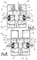
- FIG. 5 A second exemplary embodiment of the profile posts 100 is shown in FIG. 5.
- the structural shape of this profile post 100 corresponds to that of Fig. 4, i.e. the air circulation (see dash-dotted line Y) takes place via the air slot 108 through the second air passage openings 112 to the first air passage openings 103, to the channel formed between the base points of the double U 101/102 and finally to the rear ventilation spaces 5 through the third air passage openings 116 with the sliding elements 117 open channel 115.
- the special feature of the profile posts 100 shown in FIG. 5 is that the inside and outside of the double U 101/102 are thermally separated, in particular by means of glass fiber reinforced plastic strips 125, which are practically the base connections of the double U 101/102 are inserted.
- Another special feature is that the cover 114 is associated with a pair of inner screens 126 which are suspended on the cheeks 121 of the guide slot 122 and each have a second web 127 directed towards the conjugated glass pane 104.
- An internal continuous air slot 128 is formed via these second webs 127 and the air flow itself is deflected toward the inside of the glass pane 104.
- FIG. 6 A third embodiment of the profile post 100 is shown in FIG. 6.
- the basic construction corresponds to that of FIGS. 4 and 5, with the particularity or further development in that heating bands 129 are inserted in the space between the inner panels 126 and the gusset between the cheeks 121 of the guide slot 122 or the like. are clipped on.
- These heating tapes 129 are known PTC heating elements, which are self-regulating insofar as the electrical resistance of the heating element increases when the temperature rises and the current consumption and heating output decrease accordingly; when cooling, this process is reversed and the heating output increases. With these heating tapes 129 a targeted heat influence of the air flowing (see dash-dotted line Y) can be achieved; thus the rear ventilation space 5, i.e.
- the air gap between the outer facade (weather protection layer 4 in Fig. 1) and the room end wall (3 in Fig. 1) can be influenced in a targeted manner.
- FIG. 7 A fourth embodiment of the profile post 100 is shown in FIG. 7.
- the basic construction corresponds to that according to FIGS. 4, 5 and 6, in particular FIG. 6, with the special feature that tubes 132 are now integrated in the space between the inner screens 126 and the gusset between the cheeks 121 of the guide slots 122.
- a heat transfer medium such as water, oil, gas, compressed air can flow, there is the possibility of deliberately thermally influencing the ventilation space 5.
- a targeted "additional heating” can be realized in this way; however, it is also possible to specifically cool the adjacent interior.
- FIG. 8 A fifth embodiment of the profile posts 100 is shown in FIG. 8.
- the basic concept corresponds to that according to FIGS. 4 to 7, wherein in a further development of these exemplary embodiments, sound-absorbing means are arranged along the airway at suitable points. This is intended to improve the sound insulation effect already achieved through the offset of the air passage openings 103/112/116.
- the sound-absorbing means along the air path are realized in that the web 130 dividing the air flow is formed, for example, as a separate part 130 'made of sound-absorbing material and inserted into complementary receiving rails on the inside of the facing 126.
- a sound-absorbing layer 125 ' can be placed on the plastic strips 125.
- the base of the drainage channels 120 mentioned can also be covered with a soundproofing pad 120 '.
- these different sound frequencies are respectively realized using materials with different sound-insulating properties.
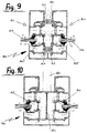
- FIG. 9 A sixth embodiment of the profile post 100 is shown in FIG. 9.
- the basic concept corresponds to that according to FIGS. 4 to 8, in particular that according to FIG. 6.
- the special feature of the profile post 100 shown in FIG. 9 is that it is not formed in one piece as in the previously described exemplary embodiments, but instead consists of two complementary halves 140/141 or is joined together.
- the two diametrically open U's 101 '/ 102' with the glass panes 104 according to the basic construction according to FIGS. 4 to 8 are therefore in this sixth embodiment each post elements that are individually manufactured and are therefore particularly suitable for the element construction.
- two guides in particular dovetail guides 142, are provided in the parting plane, which form-fittingly when assembling a weather protection layer plane, each in pairs via a correspondingly shaped bracket, in particular a dovetail bracket 143 get connected.
- the two post halves 140/141 are initially only positively connected to one another;
- at least one spring 144 or similar expansion element is provided in addition and assignment to the brackets 143, which thus give the profile post 100 as a mounting unit the required rigidity.
- the bracket 143 in the air flow Y has ventilation bores and / or ventilation slots.
- FIG. 10 A seventh embodiment of the profile post 100 is shown in FIG. 10.
- the basic construction corresponds to that according to FIGS. 4 to 8; Reference is made in particular to the problem underlying the exemplary embodiment according to FIG. 8.
- the special feature of the embodiment shown in FIG. 10 is that the air duct running between the two U's 101/102 of the profile post 100 is divided by means of a partition wall 150, in particular a partition wall made of sound-absorbing material or with sound-absorbing pads. This measure is particularly recommended if, for example, room dividers 151 or the like are connected to the inside of the profile post 100.
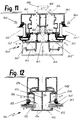
- FIG. 11 An eighth exemplary embodiment of a profiled post 100 is shown in FIG. 11. Basically, this exemplary embodiment is also based on the construction according to FIGS. 4 to 10, with the difference that here a ventilated or ventilated post profile 100 'with an integrated and openable window sash 160 is shown or designed is.
- the structural design of the profile post 100 '- analogous to the profile posts 100 described above - is likewise based on a double U 101''/102''with air passage openings 103 and a superior one Facing 106 out.
- the glass panes 104 ′′ are not used in the diametrically open U's 101 ′′ / 102 ′′, but rather in their own profile 161, which is form-fitting via corresponding seals or glazing strips 162 can be placed on the profile post 100 '.
- This profiled post 100 'itself has webs 163 which extend from the inside of the double U 101''/102''and run perpendicular to the outside, ie to the facade plane, the length of which corresponds to the width 161 of the glass panes 104''.
- the window sash 160 is closed, a flush inside is created which is only interrupted by ventilation slots 164 between the profiles 161 of the window sash on the one hand and the webs 163 of the profile posts 100 '.
- the air flow Y thus runs via the second air passage openings 112 and the first air passage openings 103 into the space between the double U 101 '' / 102 '' and then into the space between the webs 163 and the window sash 160 - and finally via the ventilation slots 164 in the interior.
- in the direction of the air flow Y in the webs 163, in addition to the double-U 101 '' / 102 '', further air passage openings 165 are provided in the webs 163, optionally with slide elements for varying the air cross section, via which the webs 163 and the Window sash 160 creates a longer flow path.
- the window sash can of course also be designed as a so-called overlapping window sash, in which case concealed ventilation slots are created).
- the exemplary embodiment explained with reference to FIG. 11 is based primarily on the same basic task as the profile post illustrated with reference to FIGS. 4 to 10, i.e. the first step is the metered supply of an air stream via a specifically designed or constructed post profile.
- the first step is the metered supply of an air stream via a specifically designed or constructed post profile.
- the result is that the build-up of atmospheric moisture as a result of windows that are too dense is counteracted and that a targeted oxygen supply to the interior is made possible.
- the structural design it should be pointed out in particular that the air duct over the air gap on the window sash 160, i.e.
- a unit 168 with, for example, heating tapes 169 of the one explained with reference to FIG. 6 To be arranged in order to influence the interior zone.
- the air in the space between the window sash profile and the profile post can also be routed past the heating pipes of the existing heating system that are integrated into the overall system.
- FIG. 12 A ninth exemplary embodiment of a profiled post 100 is shown in FIG. 12.
- the basic construction corresponds to that according to the exemplary embodiments according to FIGS. 4 to 10, with the difference being a simplification of the construction to the extent that the veneer (106 in FIGS. 4 to 8) of the profile posts 100 described above is formed in one piece with it or is omitted as a separate element.
- the basic construction of the exemplary embodiment according to FIG. 12 consists of a double U-shaped profile 170, in which the U's have a common base plane 171.
- the glass panes 104 rest on the one hand on a glass seal 172 which bears against the inside of the legs 173 of the double U-profile 170 which form the outer facade and has interruptions to the air inlet or air passage along their extension.
- the glass panes 104 are held by a normal glass seal 105, which in turn is held by the second leg 174 of the double U profile 170 by means of a cover 175.
- Parallel to this cover 175 is a partition 176.
- the air flow Y of this profile post 100 is such that the air directly on the outside of the glass pane 104 enters the interior of the profile 102 'through the interruptions in the glass seal 172 and through a gap 177 between the glass pane 104 and the partition wall 176 and an air passage 178 in the cover 175, optionally formed with sliding elements, reaches the interior zone.
- a special functional feature of the exemplary embodiment according to FIG. 12 can be seen in the fact that water penetrating with the air is separated off in the swirl chamber 179 formed by the partition wall 176 and the base plane 171 and can also be drained downward in a targeted manner. (Another swirl chamber 179 'is formed in the space between the cover 175 and the partition 176).
- the exemplary embodiment according to FIG. 12 is characterized in that the overall construction is relatively low due to the very flat outer cover.
- FIGS. 13 and 14 show two further exemplary embodiments for profile posts 100.
- the background of these further developments of the profile posts 100 according to the exemplary embodiments according to FIGS. 4 to 12 is that in addition to the air guidance in the multilayer outer facade or the associated conditioning of interior zones, a targeted water guidance in or on the facade is also to be achieved.
- This water supply should also lead to a collection of water and ultimately with the aim of integrating the water collected in the supply circuit of the building in order to reduce water consumption and relieve public disposal.
- FIG. 13 shows a tenth exemplary embodiment of a profiled post 100, which corresponds in its basic construction to the exemplary embodiment according to FIG. 6.
- the veneer 106 is not made in one part, but in two parts.
- the two halves 180, 181 of the veneer each have a rectangular cross section, the outer sides 182/183 delimiting the profile post 100 being closed surfaces.
- the other two sides are designed relative to one another and to the actual profile post 100 such that the halves 180, 181 of the veneer can be clipped onto the profile post 100.
- the inner sides 184 of the facing halves 180/181, which lie opposite one another in parallel, have ventilation slots 185 for the air flow Y.
- the parting line 186 resulting from the two-part cladding is covered with a strip 187 which can be clipped onto the outer facade sides 182 of the cladding halves 180/181, for example - as shown - semicircular profile. This results in the possibility of carrying out the veneer in element construction and, for example, to design the intersection of the strip 187 as a molded casting.
- FIG. 14 shows an eleventh exemplary embodiment of a profile post 100 as a horizontal element.
- the profile post according to FIG. 14 corresponds to that according to FIG. 13, whereby - in accordance with the use as a horizontal part - only one veneer half 180 is provided with a swirl chamber 189 analogous to the structural embodiment according to FIG.
- This veneer half 180 is used as a lower part or lower water channel for installation in a weather protection layer.
- the second, ie upper, half of the facing is formed here by a bent web 190 projecting from the actual profiled post 100, at the end of which the strip 187 is then clipped in.
- This web 190 is towards the underside, ie towards the facing half 180 buckled - kink 191 - and also serves as a drainage channel, namely as a horizontal drainage channel. The water flowing in the lower veneer half 180 and in the drainage channel of the web 190 is thus discharged laterally to vertical channels.
- the web 190 with the drainage channel is covered by a cover strip 192 which is held by holding rods 193 fixed to the profile post 100.
- the cover strip 192 can also be clipped onto the web 190 by means of complementary turf means 194, indicated by dash-dotted lines.
- Photovoltaic elements can also be integrated in the outer facade, with which - depending on preferences and / or specifications - for example the ventilation space 5 can be heated; this is particularly important in connection with openable window systems.
- the electrical power generated in the photovoitaic elements can also be used, for example, for regulation, i.e. Control of the slide elements mentioned in connection with the air passage openings and thus used to regulate the air passage cross section; moreover, it is also possible to use the power generated in the photovoltaic elements to provide sun protection, e.g. a sun joe to control.
- a moisture-swelling agent can be integrated at suitable points. This automatically closes the air path against water penetration.
Landscapes
- Engineering & Computer Science (AREA)
- General Engineering & Computer Science (AREA)
- Architecture (AREA)
- Civil Engineering (AREA)
- Structural Engineering (AREA)
- Chemical & Material Sciences (AREA)
- Combustion & Propulsion (AREA)
- Mechanical Engineering (AREA)
- Electromagnetism (AREA)
- Physics & Mathematics (AREA)
- Life Sciences & Earth Sciences (AREA)
- Sustainable Development (AREA)
- Building Environments (AREA)
Priority Applications (1)
| Application Number | Priority Date | Filing Date | Title |
|---|---|---|---|
| EP92890213A EP0591602A1 (fr) | 1992-10-06 | 1992-10-06 | Appareil de conditionnement d'air pour zones d'espaces intérieures |
Applications Claiming Priority (1)
| Application Number | Priority Date | Filing Date | Title |
|---|---|---|---|
| EP92890213A EP0591602A1 (fr) | 1992-10-06 | 1992-10-06 | Appareil de conditionnement d'air pour zones d'espaces intérieures |
Publications (1)
| Publication Number | Publication Date |
|---|---|
| EP0591602A1 true EP0591602A1 (fr) | 1994-04-13 |
Family
ID=8212299
Family Applications (1)
| Application Number | Title | Priority Date | Filing Date |
|---|---|---|---|
| EP92890213A Withdrawn EP0591602A1 (fr) | 1992-10-06 | 1992-10-06 | Appareil de conditionnement d'air pour zones d'espaces intérieures |
Country Status (1)
| Country | Link |
|---|---|
| EP (1) | EP0591602A1 (fr) |
Cited By (2)
| Publication number | Priority date | Publication date | Assignee | Title |
|---|---|---|---|---|
| EP1029998A1 (fr) * | 1999-02-16 | 2000-08-23 | Hoogovens Aluminium Profiltechnik GmbH | Dispositif pour la ventilation de l'espace entre panneaux de vitrage |
| EP1039059A3 (fr) * | 1999-03-25 | 2001-10-10 | Wishing Star Ltd | Elément de mur rideau |
Citations (5)
| Publication number | Priority date | Publication date | Assignee | Title |
|---|---|---|---|---|
| DE2817915A1 (de) * | 1978-04-24 | 1979-10-25 | Fsl Fenster System Lueftung | Fuer den einbau unterhalb von aussenfenstern vorgesehenes kastenfoermiges luftfuehrungselement |
| GB2127058A (en) * | 1982-08-03 | 1984-04-04 | Yoshida Kogyo Kk | Panel support of a curtain wall |
| DE3427545A1 (de) * | 1984-07-26 | 1986-02-06 | Georg Jäger & Sohn KG, 6310 Grünberg | Fensterfluegel |
| EP0401110A1 (fr) * | 1989-05-31 | 1990-12-05 | Peronnet épouse GRAND Mme | Profilé de façade ou de toiture évitant les risques de la condensation par la création d'un pont thermique contrôlé |
| GB2239466A (en) * | 1989-12-21 | 1991-07-03 | Hueck Fa E | Curtain wall |
-
1992
- 1992-10-06 EP EP92890213A patent/EP0591602A1/fr not_active Withdrawn
Patent Citations (5)
| Publication number | Priority date | Publication date | Assignee | Title |
|---|---|---|---|---|
| DE2817915A1 (de) * | 1978-04-24 | 1979-10-25 | Fsl Fenster System Lueftung | Fuer den einbau unterhalb von aussenfenstern vorgesehenes kastenfoermiges luftfuehrungselement |
| GB2127058A (en) * | 1982-08-03 | 1984-04-04 | Yoshida Kogyo Kk | Panel support of a curtain wall |
| DE3427545A1 (de) * | 1984-07-26 | 1986-02-06 | Georg Jäger & Sohn KG, 6310 Grünberg | Fensterfluegel |
| EP0401110A1 (fr) * | 1989-05-31 | 1990-12-05 | Peronnet épouse GRAND Mme | Profilé de façade ou de toiture évitant les risques de la condensation par la création d'un pont thermique contrôlé |
| GB2239466A (en) * | 1989-12-21 | 1991-07-03 | Hueck Fa E | Curtain wall |
Cited By (2)
| Publication number | Priority date | Publication date | Assignee | Title |
|---|---|---|---|---|
| EP1029998A1 (fr) * | 1999-02-16 | 2000-08-23 | Hoogovens Aluminium Profiltechnik GmbH | Dispositif pour la ventilation de l'espace entre panneaux de vitrage |
| EP1039059A3 (fr) * | 1999-03-25 | 2001-10-10 | Wishing Star Ltd | Elément de mur rideau |
Similar Documents
| Publication | Publication Date | Title |
|---|---|---|
| EP2594725B1 (fr) | Fenêtre | |
| DE3422151A1 (de) | Schallschutzfenster | |
| DE2139130A1 (de) | Fensterrahmen | |
| DE1810493A1 (de) | Gebaeudeaussenwand | |
| EP1624258A2 (fr) | Dispositif pour la ventilation d'un local et module de montage pour la ventilation d'un local | |
| EP2369253B1 (fr) | Dispositif d'aération pour locaux | |
| AT397977B (de) | Verglasungssystem einer gebäudefassade | |
| AT411101B (de) | Lüftungsgerät | |
| EP0591602A1 (fr) | Appareil de conditionnement d'air pour zones d'espaces intérieures | |
| EP0027581A1 (fr) | Installation d'aération | |
| DE9406653U1 (de) | Belüftungsprofil zum Ausrüsten von Fenster oder Türen | |
| DE2726252C2 (fr) | ||
| DE20200246U1 (de) | Anordnung zur Erzeugung eines Luftschottes | |
| DE4116995A1 (de) | Einrichtung zur konditionierung von innenraumzonen | |
| DE3785188T2 (de) | Lüftungsvorrichtung. | |
| AT524782B1 (de) | Verschlussvorrichtung für eine Wandöffnung | |
| EP0801275A2 (fr) | Clapet de remplacement d'air | |
| DE102020108750A1 (de) | Kastenfenster | |
| DE3443501A1 (de) | Rahmenprofil fuer ein fenster | |
| DE19849006A1 (de) | Verfahren zur Zufuhr von Außenluft aus dem Freien durch ein Fenster in einen zwangsbelüfteten Raum und Fenster dazu | |
| DE19710538C1 (de) | Mehrgeschossige Gebäudefassade mit einer Fassadenverkleidung aus plattenförmigen Fassadenelementen | |
| DE4438024A1 (de) | Frischluftsystem | |
| DE3422439C2 (de) | Fenster mit in eine Bauwerkswand einzubauendem Fensterrahmen und darin angeordnetem Flügelrahmen | |
| DE8102063U1 (de) | Rolladen | |
| WO1999050523A1 (fr) | Procede d'amenee d'air exterieur dans une piece a ventilation forcee par une fenetre et fenetre correspondante |
Legal Events
| Date | Code | Title | Description |
|---|---|---|---|
| PUAI | Public reference made under article 153(3) epc to a published international application that has entered the european phase |
Free format text: ORIGINAL CODE: 0009012 |
|
| AK | Designated contracting states |
Kind code of ref document: A1 Designated state(s): AT BE CH DK ES FR GB GR IE IT LI LU MC NL PT SE |
|
| 17P | Request for examination filed |
Effective date: 19941004 |
|
| 17Q | First examination report despatched |
Effective date: 19960711 |
|
| 18D | Application deemed to be withdrawn |
Effective date: 19961122 |