EP1624258A2 - Dispositif pour la ventilation d'un local et module de montage pour la ventilation d'un local - Google Patents
Dispositif pour la ventilation d'un local et module de montage pour la ventilation d'un local Download PDFInfo
- Publication number
- EP1624258A2 EP1624258A2 EP05405276A EP05405276A EP1624258A2 EP 1624258 A2 EP1624258 A2 EP 1624258A2 EP 05405276 A EP05405276 A EP 05405276A EP 05405276 A EP05405276 A EP 05405276A EP 1624258 A2 EP1624258 A2 EP 1624258A2
- Authority
- EP
- European Patent Office
- Prior art keywords
- fresh air
- room
- duct
- exhaust
- air duct
- Prior art date
- Legal status (The legal status is an assumption and is not a legal conclusion. Google has not performed a legal analysis and makes no representation as to the accuracy of the status listed.)
- Withdrawn
Links
Images




Classifications
-
- F—MECHANICAL ENGINEERING; LIGHTING; HEATING; WEAPONS; BLASTING
- F24—HEATING; RANGES; VENTILATING
- F24F—AIR-CONDITIONING; AIR-HUMIDIFICATION; VENTILATION; USE OF AIR CURRENTS FOR SCREENING
- F24F12/00—Use of energy recovery systems in air conditioning, ventilation or screening
- F24F12/001—Use of energy recovery systems in air conditioning, ventilation or screening with heat-exchange between supplied and exhausted air
- F24F12/006—Use of energy recovery systems in air conditioning, ventilation or screening with heat-exchange between supplied and exhausted air using an air-to-air heat exchanger
-
- F—MECHANICAL ENGINEERING; LIGHTING; HEATING; WEAPONS; BLASTING
- F24—HEATING; RANGES; VENTILATING
- F24F—AIR-CONDITIONING; AIR-HUMIDIFICATION; VENTILATION; USE OF AIR CURRENTS FOR SCREENING
- F24F7/00—Ventilation
- F24F7/04—Ventilation with ducting systems, e.g. by double walls; with natural circulation
- F24F7/06—Ventilation with ducting systems, e.g. by double walls; with natural circulation with forced air circulation, e.g. by fan positioning of a ventilator in or against a conduit
- F24F7/08—Ventilation with ducting systems, e.g. by double walls; with natural circulation with forced air circulation, e.g. by fan positioning of a ventilator in or against a conduit with separate ducts for supplied and exhausted air with provisions for reversal of the input and output systems
-
- Y—GENERAL TAGGING OF NEW TECHNOLOGICAL DEVELOPMENTS; GENERAL TAGGING OF CROSS-SECTIONAL TECHNOLOGIES SPANNING OVER SEVERAL SECTIONS OF THE IPC; TECHNICAL SUBJECTS COVERED BY FORMER USPC CROSS-REFERENCE ART COLLECTIONS [XRACs] AND DIGESTS
- Y02—TECHNOLOGIES OR APPLICATIONS FOR MITIGATION OR ADAPTATION AGAINST CLIMATE CHANGE
- Y02B—CLIMATE CHANGE MITIGATION TECHNOLOGIES RELATED TO BUILDINGS, e.g. HOUSING, HOUSE APPLIANCES OR RELATED END-USER APPLICATIONS
- Y02B30/00—Energy efficient heating, ventilation or air conditioning [HVAC]
- Y02B30/56—Heat recovery units
Definitions
- the invention relates to a device and a built-in module for room ventilation.
- a heated room such as a living room or office space, can be continuously supplied with fresh air.
- window fittings are known with which the window can be pushed to side or tilt to ventilate the room.
- An object of the invention is to provide a device for room ventilation, with a continuous supply of fresh air with minimal heat loss is possible.
- the supply of the room with fresh air and the removal of the exhaust air from the room is passive, that is, without electrical energy is consumed.
- the object is achieved by a device for room ventilation with the features according to claim 1.
- the object is also achieved by a built-in module for room ventilation with the features of claim 11.
- the device for room ventilation has a fresh air duct which can be installed in a wall of the room and via which fresh air can be supplied to the room.
- the device also has an installable into the wall of the room exhaust duct through which exhaust air from the room can be discharged.
- the device has a heat exchanger, via which the exhaust air duct is coupled to the fresh air duct.
- the installation module according to the invention for room ventilation which is installed in a wall of the room or in a window, has a housing in which a fresh air duct is provided, via which the room fresh air can be supplied.
- a fresh air duct is provided in the housing, via the exhaust air from the room can be discharged.
- a heat exchanger is provided in the housing, via which the exhaust air duct is coupled to the fresh air duct.
- the heat exchanger on thermally conductive fins.
- the slats have aluminum or copper on. As a result, the heat exchange between the fresh air and the exhaust air can be improved.
- the slats are U-shaped or formed as webs. Such slats are easy to prepare, easily connectable to the wall of the fresh air duct and the exhaust duct and have sufficient stability.
- the fins are provided in the fresh air duct and the exhaust duct, because thereby the heat exchange between the fresh air and the exhaust air can be improved.
- an exhaust air inlet and the fresh air duct having a fresh air outlet, wherein the exhaust air inlet and the exhaust air outlet are arranged adjacent.
- the inventive device for room ventilation has a ventilation flap, by means of which the fresh air duct and the exhaust duct are closed. This ensures that the room is ventilated only when it is really desired.
- the inventive device for room ventilation may have an air filter which is arranged in the fresh air duct. This has the advantage that the fresh air flowing into the room in advance cleaned of dust particles, thereby reducing the pollution of the room by dust is reduced.
- the air filter may be equipped with a microfiber-coated element. This has a sufficiently high filtration effect and can be cleaned at any time or replaced by a new one.
- the fresh air duct is arranged in the interior of the exhaust air duct.
- the housing may have a thermal barrier coating. This ensures that the built-in module does not form a cold bridge. With the help of a sound insulation layer can also be achieved a sufficient sound insulation.
- the combination of fresh air duct, exhaust duct and heat exchanger is referred to as a room ventilation device. If these components are combined to form a single installation unit, the following is spoken of by a built-in module for room ventilation. With the device for room ventilation, it is possible that their individual components are assembled and installed on site. The device for room ventilation can also be implemented as a built-in module.
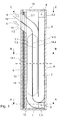
- FIG. 1 shows a first embodiment the device for room ventilation in elevation shown in the side view.
- the device has a fresh air duct 1 with a fresh air inlet 1.1, through which fresh air enters, and a fresh air outlet 1.2, from which the fresh air emerges.
- the fresh air outlet 1.2 is arranged on the inside of the wall, so that the fresh air flows into the room.
- an exhaust duct 2 is provided which has on the inside of the wall an exhaust air inlet 2.1 and on the outside of the wall and thus on the outside of the building an exhaust outlet 2.2.
- the exhaust air flows, as indicated by the arrow 5, in the exhaust duct 2 and exits the room or from the building through the exhaust outlet 2.2, as indicated by the arrow 6, from.
- the exhaust air duct 2 and the fresh air duct 1 extend, as shown in Figure 1, substantially parallel to each other.
- the fresh air duct 1 and the exhaust duct 2 may be formed as tubes and formed from sheet metal.
- both the fresh air duct 1 and the exhaust duct 2 one or more heat exchanger fins 7.1 and 7.2.
- a ventilation flap 15 is provided on the side facing the room of the device for room ventilation.
- the ventilation flap 15 is in Figure 1 in the closed state by the reference numeral 15 'and in the open state by the reference numeral 15''.
- the inventive device for room ventilation can be constructed as a built-in module.
- This has the advantage that it can be industrially prefabricated and installed as a compact component on the site in a corresponding recess on the outer wall quickly and easily can be.
- the installation module has a housing which comprises an inner wall 9, a bottom 12, an outer wall 8 and a cover 13.
- the housing may additionally have an insulation 10 for thermal and / or acoustic insulation. It can be applied to the inner wall 9 of the housing, as shown in Figure 1, the insulation 10 in conjunction with a metal foil or plate 11.
- the first embodiment of the device according to the invention for room ventilation is shown in plan view along the section A-A.
- the side walls 16 and 19 of the housing may additionally be insulated.
- only the side wall 16 of the housing with an insulation 17 and a metal foil or plate 18 is provided.
- the first embodiment of the device according to the invention for room ventilation is shown in plan view along the section BB.
- the heat exchanger fins 7.1, which are arranged in the fresh air duct 1, and the heat exchanger fins 7.2, which are arranged in the exhaust air duct 2, are U-shaped and thermally conductive.
- copper and aluminum is suitable because of their high conductivity.
- the U-shaped blades 7.1 and 7.2 are easy to prepare, easily with the partition 14.3, which separates the fresh air duct 1 from the exhaust duct 2, connectable and have a sufficiently high stability.
- the heat exchanger fins 7.1 and 7.2 may instead be formed as extruded webs of aluminum, which are interconnected via a partition plate, which is not shown in the figures. To the length of the exhaust duct 2, this can be equipped with an additional partition 14.2.
- FIG. 4 the first embodiment of the device according to the invention for room ventilation is shown in plan view along the section C-C.
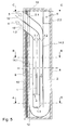
- FIG. 5 a second embodiment of the device for room ventilation in elevation is shown in the side view.
- the second embodiment differs from the first embodiment in that the fresh air duct 1 is arranged in the interior of the exhaust air duct 2.
- the fresh air inlet 1.1 of the fresh air duct 1 is no longer arranged vertically below the exhaust air outlet 2.2, but laterally offset from it.
- the surface of the heat exchanger element is larger than in the first embodiment, whereby in the second embodiment, a higher and thus improved efficiency is achieved.
- FIG 7 the second embodiment of the device for room ventilation according to the invention in plan view along the section BB is shown.
- the heat exchanger fins 7.1 and 7.2 are shorter in the second embodiment than in the first embodiment. Overall, despite the same distance between the heat exchanger fins, a total of more heat exchanger fins can be arranged in the second embodiment than in the first embodiment.
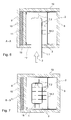
- FIG. 9 a third embodiment of the device for room ventilation in elevation is shown in the side view.
- the third embodiment differs essentially from the first embodiment shown in FIG. 1 in that the fresh air inlet 1.1 and the exhaust air outlet 2.2 are not arranged at right angles to the fresh air outlet 1.2 and exhaust air inlet 2.1, but at the same angle as the fresh air outlet 1.2 and the exhaust air inlet 2.1 exit from the installation module.
- FIG. 10 the third embodiment of the device according to the invention for room ventilation is shown in plan view along the section AA.
- the third embodiment is shown in plan view along section B-B.
- the heat exchanger fins 7.1 and 7.2 are formed in the third embodiment as well as in the first embodiment.
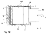
- FIG. 12 the third embodiment is shown in plan view along section C-C.
- the supply of fresh air and the discharge of the used room air takes place in all embodiments in two separate channels 1 and 2, which are integrated in a built-in module.
- the built-in module can be easily installed in the facade. Both the fresh air flow and the exhaust air flow are caused by the static height between the inlet and outlet of the air and by the temperature difference between the interior of the room and the building environment. This has the advantage that no electrical energy is consumed to allow the exchange of air.
- the geometry of the fresh air duct 1, the exhaust duct 2 and the heat exchanger fins 7.1 and 7.2 is chosen so that an optimal, natural air flow is made possible.
- the room ventilation device is designed so that it can be easily cleaned at any time.
- the inner wall 9 is removable.
- the heat exchanger element with the heat exchanger fins 7.1, 7.2 can be removed and cleaned with water.
- the housing 8, 9, 12, 13 can be cleaned with a damp cloth.
- an air filter may be provided which is equipped, for example, with a microfiber-coated element.
- the heat exchanger fins 7.1 and 7.2 may additionally be provided with nubs to filter the incoming fresh air.
- the fresh air duct 1 is coupled to the exhaust air duct 2 through the heat exchanger equipped with heat exchanger fins 7.1 and 7.2.
- the heat exchanger fins 7.1 and 7.2 which may also be referred to as ribs, are welded or soldered onto the separating plate 14.3. As the fresh air flows along the heat exchanger fins 7.1, it heats up and maintains buoyancy. At the same time, warm room air enters the top of the exhaust air inlet 2.1 as exhaust air and is guided downwards via the exhaust air duct 2 past the heat exchanger fins 7.2.
- the housing can be made of wood or metal and is installed in the façade, with a part on the outside and a part on the inside of the building.
- the housing thus forms part of the exterior wall of the room.
- the air inlets 1.1 and 2.1 and the air outlets 1.2 and 2.2 may be made of chromium-nickel steel or aluminum, for example.
- the fresh air inlet 1.1 and the exhaust outlet 2.2 can be sealed to the facade skin.
- adjustable inserts can be provided, with which the fresh air inlet 1.1 and the exhaust outlet 2.2 can be extended, so that they can be adapted to the wall thickness of the building.
- wires can be welded onto the inserts or a correspondingly fine-meshed network can be installed.
- the housing can be equipped with additional heat and sound insulation.
- the front cover 9 has an opening for the fresh air outlet 1.2 and the exhaust air inlet 2.1. With the ventilation flap 15, the opening can be closed if necessary.
- the walls 14.1, 14.2, 14.3 of the fresh air duct 1 and the exhaust duct 2 may be made of sheet metal with a thickness between 0.4 and 1 mm.
- the fresh air duct 1 has a radius of 100 to 130 mm in the lower region.
- the sheets, which together form the fresh air duct 1 and the exhaust duct 2 are folded and produced as standard components in series.
- the heat exchanger fins 7.1 and 7.2 are adapted to the air flow, so that the air resistance is as small as possible. Basically, the smaller the air resistance at the largest possible heat exchanger surface, the higher the efficiency.
Landscapes
- Engineering & Computer Science (AREA)
- Chemical & Material Sciences (AREA)
- Combustion & Propulsion (AREA)
- Mechanical Engineering (AREA)
- General Engineering & Computer Science (AREA)
- Building Environments (AREA)
- Duct Arrangements (AREA)
Applications Claiming Priority (1)
| Application Number | Priority Date | Filing Date | Title |
|---|---|---|---|
| CH01295/04A CH696891A5 (de) | 2004-08-02 | 2004-08-02 | Einrichtung zur Raumlüftung und Einbaumodul zur Raumlüftung |
Publications (2)
| Publication Number | Publication Date |
|---|---|
| EP1624258A2 true EP1624258A2 (fr) | 2006-02-08 |
| EP1624258A3 EP1624258A3 (fr) | 2006-12-20 |
Family
ID=35219558
Family Applications (1)
| Application Number | Title | Priority Date | Filing Date |
|---|---|---|---|
| EP05405276A Withdrawn EP1624258A3 (fr) | 2004-08-02 | 2005-03-30 | Dispositif pour la ventilation d'un local et module de montage pour la ventilation d'un local |
Country Status (2)
| Country | Link |
|---|---|
| EP (1) | EP1624258A3 (fr) |
| CH (1) | CH696891A5 (fr) |
Cited By (11)
| Publication number | Priority date | Publication date | Assignee | Title |
|---|---|---|---|---|
| FR2925953A1 (fr) * | 2007-12-28 | 2009-07-03 | Atlantic Climatisation & Venti | Coffret mural double flux de renouvellement de l'air d'un local |
| EP1832818A3 (fr) * | 2006-03-06 | 2009-08-19 | STIEBEL ELTRON GmbH & Co. KG | Installation d'aération |
| FR2939873A1 (fr) * | 2008-12-15 | 2010-06-18 | Pierre Vironneau | Installation pour renouveler l'air d'une piece a partir d'un echangeur thermique double flux dispose a l'interieur |
| FR2944340A1 (fr) * | 2009-04-14 | 2010-10-15 | Iosis Concept | Installation de ventilation double flux coaxial avec pompe a chaleur integree pour le logement collectif |
| EP2378216A3 (fr) * | 2010-04-13 | 2013-07-24 | Erwin Grohmann | Dispositif d'aération |
| FR3014172A1 (fr) * | 2013-12-02 | 2015-06-05 | Scabe Innovations | Gaine aeraulique destinee a la climatisation de l'air dans un batiment d'elevage et batiment d'elevage pourvu d'une telle gaine aeraulique |
| DE202015102213U1 (de) | 2015-04-30 | 2015-07-10 | Tobias Becker | Anpassungsfähiges Fassadenelement |
| EP3214254A1 (fr) * | 2016-03-03 | 2017-09-06 | Skaala Production Oy | Dispositif de ventilation, fenêtre de ventilation et échangeur de chaleur |
| EP3214381A1 (fr) * | 2016-03-03 | 2017-09-06 | Skaala Production Oy | Dispositif de ventilation et procédé de ventilation |
| CN109386898A (zh) * | 2017-08-04 | 2019-02-26 | 广东美的制冷设备有限公司 | 空气处理模块和空调器 |
| EP4223109A1 (fr) * | 2022-02-01 | 2023-08-09 | Schauer Agrotronic GmbH | Installation de production d'énergie pour récupérer la chaleur perdue |
Family Cites Families (8)
| Publication number | Priority date | Publication date | Assignee | Title |
|---|---|---|---|---|
| DE3118053C2 (de) * | 1981-05-07 | 1985-03-14 | Günter Dipl.-Architekt 6096 Raunheim Hack | Plattenförmiges wärmedämmendes Bauelement für Fensterbrüstungen von Gebäuden |
| DE3239034A1 (de) * | 1982-08-18 | 1984-03-01 | Christoph 1000 Berlin Adam | Raumluefter mit rekuperativem waermetauscher |
| GB2138124B (en) * | 1983-03-16 | 1987-09-23 | Norcros Investments Ltd | Ventilator |
| GB2192451B (en) * | 1986-05-21 | 1990-07-04 | Paul Whyatt | Thermal transfer door |
| DE3802583A1 (de) * | 1988-01-29 | 1989-08-10 | Wetzel Alfred | Lueftungsvorrichtung fuer fenster und/oder fenstertueren zur rekuperativen be- und entlueftung von aufenthaltsraeumen |
| CH692061A5 (de) * | 1995-08-16 | 2002-01-15 | Peter Haeusler | Be- und Entlüftungsvorrichtung zur Zu- und Abfuhr von Luft in einem Gebäude. |
| DE10310435B3 (de) * | 2003-02-05 | 2004-06-03 | Helsa-Werke Helmut Sandler Gmbh & Co. Kg | Filterelement und Verfahren zu seiner Herstellung |
| EP1486637B1 (fr) * | 2003-06-12 | 2009-08-05 | Lidartech Co., Ltd. | Fenêtre avec dispositif de ventilation |
-
2004
- 2004-08-02 CH CH01295/04A patent/CH696891A5/de not_active IP Right Cessation
-
2005
- 2005-03-30 EP EP05405276A patent/EP1624258A3/fr not_active Withdrawn
Cited By (13)
| Publication number | Priority date | Publication date | Assignee | Title |
|---|---|---|---|---|
| EP1832818A3 (fr) * | 2006-03-06 | 2009-08-19 | STIEBEL ELTRON GmbH & Co. KG | Installation d'aération |
| FR2925953A1 (fr) * | 2007-12-28 | 2009-07-03 | Atlantic Climatisation & Venti | Coffret mural double flux de renouvellement de l'air d'un local |
| FR2939873A1 (fr) * | 2008-12-15 | 2010-06-18 | Pierre Vironneau | Installation pour renouveler l'air d'une piece a partir d'un echangeur thermique double flux dispose a l'interieur |
| WO2010076472A1 (fr) * | 2008-12-15 | 2010-07-08 | Pierre Vironneau | Installation pour renouveler l'air d'une pluralite de pieces a partir d'un echangeur thermique double flux dispose a l'interieur de chaque piece |
| FR2944340A1 (fr) * | 2009-04-14 | 2010-10-15 | Iosis Concept | Installation de ventilation double flux coaxial avec pompe a chaleur integree pour le logement collectif |
| EP2378216A3 (fr) * | 2010-04-13 | 2013-07-24 | Erwin Grohmann | Dispositif d'aération |
| FR3014172A1 (fr) * | 2013-12-02 | 2015-06-05 | Scabe Innovations | Gaine aeraulique destinee a la climatisation de l'air dans un batiment d'elevage et batiment d'elevage pourvu d'une telle gaine aeraulique |
| DE202015102213U1 (de) | 2015-04-30 | 2015-07-10 | Tobias Becker | Anpassungsfähiges Fassadenelement |
| WO2016173585A1 (fr) | 2015-04-30 | 2016-11-03 | Tobias Becker | Élément de façade à double paroi présentant un coussin d'air à volume variable |
| EP3214254A1 (fr) * | 2016-03-03 | 2017-09-06 | Skaala Production Oy | Dispositif de ventilation, fenêtre de ventilation et échangeur de chaleur |
| EP3214381A1 (fr) * | 2016-03-03 | 2017-09-06 | Skaala Production Oy | Dispositif de ventilation et procédé de ventilation |
| CN109386898A (zh) * | 2017-08-04 | 2019-02-26 | 广东美的制冷设备有限公司 | 空气处理模块和空调器 |
| EP4223109A1 (fr) * | 2022-02-01 | 2023-08-09 | Schauer Agrotronic GmbH | Installation de production d'énergie pour récupérer la chaleur perdue |
Also Published As
| Publication number | Publication date |
|---|---|
| CH696891A5 (de) | 2008-01-15 |
| EP1624258A3 (fr) | 2006-12-20 |
Similar Documents
| Publication | Publication Date | Title |
|---|---|---|
| EP2594725B1 (fr) | Fenêtre | |
| DE3006318A1 (de) | Lueftervorrichtung | |
| DE3043783A1 (de) | Schall- und waermeisolierendes verbundfenster mit verstellbarer schalldaemmlueftung | |
| EP1832818B1 (fr) | Installation d'aération | |
| EP2342504A1 (fr) | Système de ventilation et de climatisation modulaire intégré dans la façade | |
| CH696891A5 (de) | Einrichtung zur Raumlüftung und Einbaumodul zur Raumlüftung | |
| DE102008020941B4 (de) | Luftführungselement zum Zuführen und/oder Abführen von Luft | |
| DE202007008504U1 (de) | Vorrichtung zur Raumlüftung | |
| EP1862746A2 (fr) | Dispositif d'aération et cadre | |
| DE102012101983A1 (de) | Fenstersystem mit aktiver Belüftung | |
| DE102021118086A1 (de) | Haustechnikelement | |
| DE3030536C2 (de) | Brüstungselement zum Einbau in Fassaden | |
| DE19733075C1 (de) | Dämmsystem für Gebäudefassaden | |
| DE202005004563U1 (de) | Solarkollektor zur Lufterwärmung | |
| AT505746A1 (de) | Brandschutzanlage für gebäude | |
| DE202016008921U1 (de) | Fensterdämmelement | |
| DE10204585B4 (de) | Sonnenkollektor zum vorzugsweisen Betrieb mit gasförmigen Medien | |
| EP3086050B1 (fr) | Dispositif d'aeration decentralise encastrable | |
| DE102020134043A1 (de) | Wanddurchführungseinheit für den Anschluss eines Haustechnikgeräts | |
| DE202020001781U1 (de) | Mehrschichtiges Dämmsystem zur Dämmung eines Gebäudes | |
| DE29608561U1 (de) | Vorrichtung zur Lüftung von Gebäuderäumen | |
| CH693107A5 (de) | Lüftungsbeistoss für Türzargen. | |
| DE202026100610U1 (de) | Lüftungsvorrichtung | |
| DE4116995A1 (de) | Einrichtung zur konditionierung von innenraumzonen | |
| DE202007006436U1 (de) | Flache Be- und Entlüftungsvorrichtung mit Wärmerückgewinnung |
Legal Events
| Date | Code | Title | Description |
|---|---|---|---|
| PUAI | Public reference made under article 153(3) epc to a published international application that has entered the european phase |
Free format text: ORIGINAL CODE: 0009012 |
|
| AK | Designated contracting states |
Kind code of ref document: A2 Designated state(s): AT BE BG CH CY CZ DE DK EE ES FI FR GB GR HU IE IS IT LI LT LU MC NL PL PT RO SE SI SK TR |
|
| AX | Request for extension of the european patent |
Extension state: AL BA HR LV MK YU |
|
| PUAL | Search report despatched |
Free format text: ORIGINAL CODE: 0009013 |
|
| AK | Designated contracting states |
Kind code of ref document: A3 Designated state(s): AT BE BG CH CY CZ DE DK EE ES FI FR GB GR HU IE IS IT LI LT LU MC NL PL PT RO SE SI SK TR |
|
| AX | Request for extension of the european patent |
Extension state: AL BA HR LV MK YU |
|
| 17P | Request for examination filed |
Effective date: 20070620 |
|
| AKX | Designation fees paid |
Designated state(s): AT DE |
|
| 17Q | First examination report despatched |
Effective date: 20070831 |
|
| STAA | Information on the status of an ep patent application or granted ep patent |
Free format text: STATUS: THE APPLICATION IS DEEMED TO BE WITHDRAWN |
|
| 18D | Application deemed to be withdrawn |
Effective date: 20100921 |