EP0591655A1 - Récepteur pour radiodiffusion RDS - Google Patents
Récepteur pour radiodiffusion RDS Download PDFInfo
- Publication number
- EP0591655A1 EP0591655A1 EP93113045A EP93113045A EP0591655A1 EP 0591655 A1 EP0591655 A1 EP 0591655A1 EP 93113045 A EP93113045 A EP 93113045A EP 93113045 A EP93113045 A EP 93113045A EP 0591655 A1 EP0591655 A1 EP 0591655A1
- Authority
- EP
- European Patent Office
- Prior art keywords
- radio receiver
- switching
- delayed
- received audio
- received
- Prior art date
- Legal status (The legal status is an assumption and is not a legal conclusion. Google has not performed a legal analysis and makes no representation as to the accuracy of the status listed.)
- Withdrawn
Links
Images

Classifications
-
- H—ELECTRICITY
- H04—ELECTRIC COMMUNICATION TECHNIQUE
- H04H—BROADCAST COMMUNICATION
- H04H40/00—Arrangements specially adapted for receiving broadcast information
- H04H40/18—Arrangements characterised by circuits or components specially adapted for receiving
-
- H—ELECTRICITY
- H04—ELECTRIC COMMUNICATION TECHNIQUE
- H04H—BROADCAST COMMUNICATION
- H04H20/00—Arrangements for broadcast or for distribution combined with broadcast
- H04H20/26—Arrangements for switching distribution systems
-
- H—ELECTRICITY
- H04—ELECTRIC COMMUNICATION TECHNIQUE
- H04H—BROADCAST COMMUNICATION
- H04H2201/00—Aspects of broadcast communication
- H04H2201/10—Aspects of broadcast communication characterised by the type of broadcast system
- H04H2201/13—Aspects of broadcast communication characterised by the type of broadcast system radio data system/radio broadcast data system [RDS/RBDS]
Definitions
- the invention relates to a radio receiver according to the preamble of the main claim.
- RDS receiver In known radio receivers with a device for decoding radio data signals - hereinafter referred to as RDS receiver - especially car radios, it is first checked from time to time whether a transmitter with a different frequency is worth receiving (quality check), and furthermore whether it broadcasts the same program (program identification (PI) check).
- quality check takes 20 ms to 30 ms and the PI check takes 150 ms to 300 ms, which leads to annoying crackling noises during phase jumps and mute breaks because there is no audio signal the received frequency is available.
- DOS 35 05 720 From DOS 35 05 720 it is known to receive the signals received in a radio receiver in order to delay the duration of a fault check and, if necessary, to fade in the delayed signal instead of the disturbed signal during the duration of the fault in the playback.
- the present invention achieves the object of further reducing the disruption to playback during the fade-in process.
- a further development of the invention is that the undelayed received audio signal is forwarded to a playback device during a first operating state and that the delayed received audio signal is forwarded to the playback device during a second operating state in which there is a pause check.
- radio receivers For recording and querying traffic announcements at any time, radio receivers have become known in which a digital memory - a so-called voice memory - is provided for recording the traffic announcements.
- An economic advantage of a radio receiver according to the invention results from the fact that at least partially a speech memory is used as a digital memory for recording traffic announcements.
- the trial switching to another frequency is preferably prevented when recording traffic announcements.
- the audio signals can be delayed in the baseband (as signals L and R) or as multiplex signals and be checked for breaks.
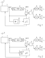
- a receiving part 1 contains all of the circuitry required for receiving the antenna 2, as well as for demodulation.
- the demodulated audio signal or, in the case of stereo reception, the multiplex signal MPX is supplied on the one hand directly and on the other hand via a delay device 3 to a controllable changeover switch 4.
- the delay device consists, in a manner known per se, of an analog / digital converter, a memory (RAM) and a digital / analog converter.
- the memory can be organized, for example, as a FIFO memory, that is to say the signals are read out in the same order as they are written in, but are delayed by a predefinable time. This time is, for example, 300 ms.
- the devices required for the reproduction of the audio signals are connected to the output of the changeover switch 4, of which only one stereo decoder 4 'in the figures and one NF amplifier 5, 5' and one loudspeaker 6, 6 'each for stereo reproduction are shown.
- a microcomputer 7 controls various functions of the radio receiver, not shown in detail. Among other things, the output of the microcomputer 7 is connected to a control input of the receiving part 1 and can therefore tune the receiving part 1. Furthermore, the microcomputer 7 is connected to a control input of the switch 4. Controlled by the microcomputer 7, either the undelayed multiplex signal MPX or the delayed multiplex signal MPX 'can thus be routed to the playback devices.
- the undelayed multiplex signal MPX is fed to a circuit 8 for detecting pauses, which is essentially formed from an amplitude demodulator and a threshold value circuit.
- a digital signal is present at the output of the circuit 8, which indicates whether the respective amplitude of the multiplex signal MPX is below a predetermined value, which is recognized as a pause. This signal is fed to the microcomputer 7.
- no circuit for detecting the pauses is provided in the exemplary embodiment shown in FIG. 2.
- This task is performed by the microcomputer 7 ', which contains an analog / digital converter 9, the input of which can be fed with the undelayed multiplex signal MPX.
- Fig. 3 shows the time course of the amplitudes of the multiplex signal MPX (line a) and the multiplex signal MPX '(line b). It is assumed that in the multiplex signal MPX there is a pause of, for example, 300 ms and several shorter pauses. Since the delay between the two signals is also 300 ms, the pause in the delayed multiplex signal MPX 'begins when the pause in the undelayed multiplex signal MPX has ended. This makes it possible to recognize from the undelayed multiplex signal MPX whether there is a pause that is at least as long as the time required for temporary switching. If the switchover is made during the pause of the delayed multiplex signal MPX ', there is no interference during playback.
- the delay device 3 is to be designed in such a way that there is no deterioration in the quality of the reproduction.
- the switch 4 is in the lower position in a first operating state (normal operation), so that the undelayed signal is reproduced. This always happens when the quality of the received signal does not require a test-based switchover to another reception frequency. However, if a test of another reception frequency or its program identification signals appears to be necessary, the changeover switch 4 is switched to the upper position. To avoid a cracking noise that may occur, this can already take place during a pause. The test is carried out at the first pause after the switchover, which is long enough to test switchover the other frequency, as described in connection with FIG. 3.
- a read / write memory 11 which is already present in the radio receiver and is provided for storing traffic announcements, is used to delay the audio signal for the purposes of the invention.
- the read / write memory - also called voice memory - is corresponding to the device 3 in FIG. 1 via an analog / digital converter 12 with the output of the receiving part 1 and with a digital / analog converter 13 with an input of the changeover switch 4 connected. Suitable signals are supplied to the voice memory 11 by the microcomputer 14 to control the writing and reading processes.
- a circuit 8 is provided for the detection of pauses.
- the audio signal is fed to a traffic radio decoder 15, which feeds the decoded traffic radio signals, such as station identification and announcement identification, to the microcomputer 14.
- the temporary switchover takes place in accordance with the embodiments according to FIGS. 1 and 2.
- the voice memory 11 is operated by the microcomputer 14 in such a way that it only outputs the audio signal for the time required for the check delayed.
- the traffic radio decoder 15 communicates this to the microcomputer 14, whereupon the latter controls the voice memory 11 for reading in the traffic announcement. If a traffic announcement is to be listened to, the changeover switch 4 is brought into the lower position via an operating unit (not shown in FIG. 4) and the microcomputer 14 and the voice memory 11 is controlled accordingly for reading. Expediently when recording traffic announcements, a trial switching to other frequencies is prevented, since the voice memory is required to record the traffic announcement or a change in the reception frequency is not desirable. When playing back stored traffic announcements, the test switching can easily be carried out, since an interruption in reception then does not interfere.
Landscapes
- Engineering & Computer Science (AREA)
- Signal Processing (AREA)
- Circuits Of Receivers In General (AREA)
Applications Claiming Priority (2)
| Application Number | Priority Date | Filing Date | Title |
|---|---|---|---|
| DE19924233758 DE4233758C1 (de) | 1992-10-07 | 1992-10-07 | Rundfunkempfänger |
| DE4233758 | 1992-10-07 |
Publications (1)
| Publication Number | Publication Date |
|---|---|
| EP0591655A1 true EP0591655A1 (fr) | 1994-04-13 |
Family
ID=6469884
Family Applications (1)
| Application Number | Title | Priority Date | Filing Date |
|---|---|---|---|
| EP93113045A Withdrawn EP0591655A1 (fr) | 1992-10-07 | 1993-08-14 | Récepteur pour radiodiffusion RDS |
Country Status (2)
| Country | Link |
|---|---|
| EP (1) | EP0591655A1 (fr) |
| DE (1) | DE4233758C1 (fr) |
Cited By (3)
| Publication number | Priority date | Publication date | Assignee | Title |
|---|---|---|---|---|
| DE19614322A1 (de) * | 1996-04-11 | 1997-10-16 | Grundig Ag | Verfahren für den Empfang und die Auswertung von RDS-Datenströmen mehrerer Sender |
| WO2001056178A3 (fr) * | 2000-01-29 | 2002-04-25 | Klaus-Erwin Groeger | Procede pour cacher des interruptions de reproduction de signaux de radiodiffusion reçus |
| WO2016117110A1 (fr) * | 2015-01-23 | 2016-07-28 | パイオニア株式会社 | Dispositif de réception et procédé de traitement de signal reçu |
Families Citing this family (6)
| Publication number | Priority date | Publication date | Assignee | Title |
|---|---|---|---|---|
| DE4421694B4 (de) * | 1994-06-21 | 2005-05-25 | Robert Bosch Gmbh | Schaltungsanordnung für ein Autoradio zur Erzeugung kurzzeitiger Stummschaltimpulse |
| DE59510754D1 (de) * | 1995-10-02 | 2003-08-28 | Blaupunkt Werke Gmbh | Schaltungsanordnung für ein Autoradio zur Erzeugung kurzzeitiger Stummschaltimpulse |
| DE19542877A1 (de) * | 1995-11-17 | 1997-05-22 | Teves Gmbh Alfred | Verfahren zur Wiedergabe von Nachrichten |
| EP0845873A1 (fr) * | 1996-11-29 | 1998-06-03 | STMicroelectronics S.r.l. | Méthode de commutation vers des fréquences alternatives pendant les pauses dans le programme diffusé dans un récepteur de radiodiffusion |
| DE102004041522A1 (de) * | 2004-08-27 | 2006-03-02 | Robert Bosch Gmbh | Empfangsschaltung |
| FR3117712B1 (fr) * | 2020-12-16 | 2024-03-15 | Continental Automotive Gmbh | procédé de changement de fréquence depuis une première fréquence de réception radio vers une deuxième fréquence de réception dans un système de réception radio comportant un unique récepteur |
Citations (4)
| Publication number | Priority date | Publication date | Assignee | Title |
|---|---|---|---|---|
| US4498194A (en) * | 1983-01-31 | 1985-02-05 | General Electric Company | Multifrequency scanning receiver with priority frequency monitoring |
| JPH03148922A (ja) * | 1989-11-02 | 1991-06-25 | Alpine Electron Inc | 自動追従式ラジオ受信機 |
| EP0445885A1 (fr) * | 1990-03-09 | 1991-09-11 | Philips Electronique Grand Public | Récepteur avec des moyens d'acquisition et de comparaison des données d'identification de deux canaux de transmission |
| EP0497116A2 (fr) * | 1991-02-01 | 1992-08-05 | HENZE, Werner | Récepteur de radiodiffusion avec RDS |
Family Cites Families (4)
| Publication number | Priority date | Publication date | Assignee | Title |
|---|---|---|---|---|
| DE3212615C2 (de) * | 1982-04-05 | 1984-09-06 | Bayerische Motoren Werke AG, 8000 München | Verfahren zum Umschalten der Wiedergabe eines Rundfunksignals auf ein anderes Rundfunksignal und Schaltungsanordnung zur Durchführung des Verfahrens |
| DE3505720A1 (de) * | 1985-02-19 | 1986-08-21 | Grundig E.M.V. Elektro-Mechanische Versuchsanstalt Max Grundig holländ. Stiftung & Co KG, 8510 Fürth | Verfahren zum stoerungsbedingten umschalten von rundfunksignalen gleichen modulationsinhaltes |
| DE3709523A1 (de) * | 1987-03-23 | 1988-10-13 | Bosch Gmbh Robert | Rundfunkempfaenger mit mindestens einem verkehrsfunkdecoder |
| DE59209341D1 (de) * | 1991-02-01 | 1998-07-02 | Blaupunkt Werke Gmbh | Verfahren zur Überbrückung von Audiosignalunterbrechungen |
-
1992
- 1992-10-07 DE DE19924233758 patent/DE4233758C1/de not_active Expired - Fee Related
-
1993
- 1993-08-14 EP EP93113045A patent/EP0591655A1/fr not_active Withdrawn
Patent Citations (4)
| Publication number | Priority date | Publication date | Assignee | Title |
|---|---|---|---|---|
| US4498194A (en) * | 1983-01-31 | 1985-02-05 | General Electric Company | Multifrequency scanning receiver with priority frequency monitoring |
| JPH03148922A (ja) * | 1989-11-02 | 1991-06-25 | Alpine Electron Inc | 自動追従式ラジオ受信機 |
| EP0445885A1 (fr) * | 1990-03-09 | 1991-09-11 | Philips Electronique Grand Public | Récepteur avec des moyens d'acquisition et de comparaison des données d'identification de deux canaux de transmission |
| EP0497116A2 (fr) * | 1991-02-01 | 1992-08-05 | HENZE, Werner | Récepteur de radiodiffusion avec RDS |
Non-Patent Citations (1)
| Title |
|---|
| PATENT ABSTRACTS OF JAPAN vol. 15, no. 375 (E - 1114) 20 September 1991 (1991-09-20) * |
Cited By (5)
| Publication number | Priority date | Publication date | Assignee | Title |
|---|---|---|---|---|
| DE19614322A1 (de) * | 1996-04-11 | 1997-10-16 | Grundig Ag | Verfahren für den Empfang und die Auswertung von RDS-Datenströmen mehrerer Sender |
| EP0801476A3 (fr) * | 1996-04-11 | 2000-05-10 | GRUNDIG Aktiengesellschaft | Méthode de réception et de l'évaluation des données RDS en provenance d'une pluralité d'émetteurs |
| WO2001056178A3 (fr) * | 2000-01-29 | 2002-04-25 | Klaus-Erwin Groeger | Procede pour cacher des interruptions de reproduction de signaux de radiodiffusion reçus |
| US6961548B2 (en) | 2000-01-29 | 2005-11-01 | Robert Bosch Gmbh | Method for masking interruptions on playback of received radio signals |
| WO2016117110A1 (fr) * | 2015-01-23 | 2016-07-28 | パイオニア株式会社 | Dispositif de réception et procédé de traitement de signal reçu |
Also Published As
| Publication number | Publication date |
|---|---|
| DE4233758C1 (de) | 1994-01-27 |
Similar Documents
| Publication | Publication Date | Title |
|---|---|---|
| EP0497116B1 (fr) | Récepteur de radiodiffusion avec RDS | |
| DE69427260T2 (de) | Radiodatenempfänger mit durch Programmartdaten gesteuerter Stromversorgungsschaltung | |
| EP0531725B1 (fr) | Récepteur à onde ultracourtes à plusieurs antennes | |
| EP0610313B1 (fr) | Systeme de radiodiffusion et recepteur de radiodiffusion | |
| DE3131292C2 (fr) | ||
| EP0497115A2 (fr) | Récepteur de radiodiffusion avec RDS | |
| DE2731940A1 (de) | Stereophonischer fm-empfaenger | |
| DE2929647A1 (de) | Ukw-stero-empfaenger | |
| DE4233758C1 (de) | Rundfunkempfänger | |
| EP0364749B1 (fr) | Récepteur radio | |
| DE4103061C2 (de) | Rundfunkempfänger | |
| EP0767554B1 (fr) | Récepteur avec système RDS comportant un récepteur supplémentaire | |
| DE4408930A1 (de) | Kombinationsgerät | |
| DE4136068A1 (de) | Rundfunkuebertragungssystem und rundfunkempfaenger fuer ukw-fm und digitalen rundfunk (dab) | |
| DE3016071A1 (de) | Rundfunkempfaenger mit automatischer abstimmschaltung | |
| EP0428866B1 (fr) | Procédé et dispositif pour supprimer les changements d'émetteur dans des récepteurs avec RDS dûs à des perturbations locales | |
| EP1219027B1 (fr) | Procede et dispositif permettant de faire fonctionner un dispositif audio dans un vehicule automobile | |
| DE4239759C2 (de) | Verfahren zum Umschalten auf eine empfangswürdige Alternativfrequenz eines RDS-Empfängers | |
| DE19701042C2 (de) | Verfahren zur Auswertung von digitalen Signalen | |
| EP0714222B1 (fr) | Processeur de signaux pseudostéréo pour récepteur mobile | |
| DE69022676T2 (de) | Fahrzeug-Empfänger. | |
| DE3934282C2 (de) | RDS-Empfänger | |
| EP1271790B1 (fr) | Récepteur radio | |
| DE4227680C2 (de) | FM-Empfänger mit RDS-Auswertung | |
| DE19830688B4 (de) | Rundfunkempfänger für ein Fahrzeug |
Legal Events
| Date | Code | Title | Description |
|---|---|---|---|
| PUAI | Public reference made under article 153(3) epc to a published international application that has entered the european phase |
Free format text: ORIGINAL CODE: 0009012 |
|
| AK | Designated contracting states |
Kind code of ref document: A1 Designated state(s): AT DE ES FR GB IT |
|
| 17P | Request for examination filed |
Effective date: 19940415 |
|
| 17Q | First examination report despatched |
Effective date: 19970326 |
|
| 18D | Application deemed to be withdrawn |
Effective date: 19971007 |